Category Archives: Spacecraft and Missions

First Ever 3D Printed Object Made From Asteroid / Meteorite Metals

Peter Lobner

In a 31 December 2015 post, I discussed the “U.S. Commercial Space Launch Competitiveness Act,” which was signed into law on 25 November 2015 and established, among other things, the legal basis for asteroid mining. I also identified the firm Planetary Resources (http://www.planetaryresources.com/ – home-intro) as one of the firms having a business interest in asteroid prospecting.

Today, at the Consumer Electronics Show (CES) today in Las Vegas, Planetary Resources announced that they, in collaboration with their partner firm, 3D Systems (http://www.3dsystems.com), have produced the first ever direct metal print of an object using metals recovered from an asteroid (or meteorite) that impacted Earth.

PlanetaryResources_3DSystems_Meteorite2_LOW-680x355 
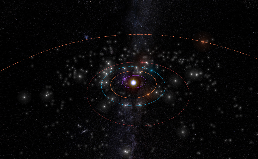
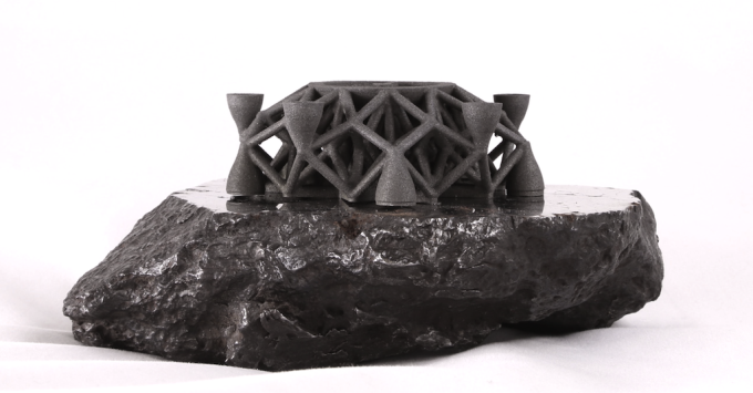
Source: Planetary Resources

In the Planetary Resources announcement, they stated that the material used for 3D printing:

  • “…was sourced from the Campo Del Cielo impact near Argentina, and is composed of iron, nickel and cobalt – similar materials to refinery grade steel.”
  • “ …was pulverized, powdered and (then) processed on the new 3D Systems ProX DMP 320 metals 3D printer.”

You can read the announcement at the following link:

http://www.planetaryresources.com/2016/01/planetary-resources-and-3d-systems-reveal-first-ever-3d-printed-object-from-asteroid-metals/

You can read more about the ProX DMP 320 3D printer at the following link:

http://www.3dsystems.com/3d-printers/production/prox-dmp-320

The milestone announced today demonstrates a key capability needed for building research bases and commercial facilities in space using raw materials found on another body in our solar system.

Imagine what the cargo manifest will be on future space missions to destinations that have useful natural resources that can be mined and prepared on site for use in various 3D printing (additive manufacturing) activities. The early missions will need to carry pre-fabricated structures for an initial base, tools for initial mining and manufacturing work, other items manufactured on Earth, and consumables. Once the on-site mining and manufacturing facilities reach an initial operating capability, the extended supply chain from Earth can be reduced commensurate with the capabilities of the local supply chain.

For more background information on this subject, National Academies Press published the  report, “3D Printing in Space”, which you can download for free at the following link if you have set up a MyNAP account:

http://www.nap.edu/catalog/18871/3d-printing-in-space
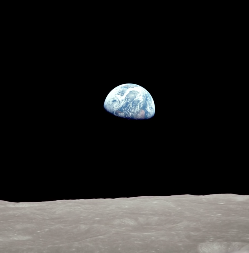
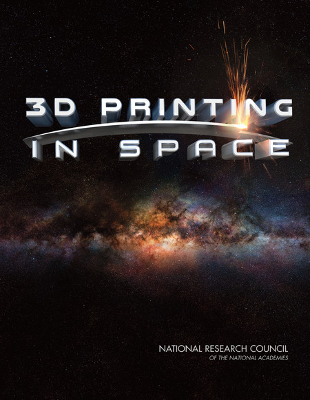
18871-0309310083-450  Source:  NAP

Opportunities for 3D printing in space addressed in this NAP report include: manufacturing new or replacement parts needed on a space vehicle or off-Earth facility; creating structures that are difficult to produce on, or transport from, Earth; creating a fully-printed spacecraft; using resources available on planetary surfaces; recycling materials in space; and establishing a free-flying fabrication facility.  The report also includes roadmaps for NASA and the U.S. Air Force deployment of 3D printing capabilities in space.

This is just the start. Manufacturing in space using locally sourced materials will revolutionize our approach for building a permanent human presence off the planet Earth.

Legal Basis Established for U.S. Commercial Space Launch Industry Self-regulation and Commercial Asteroid Mining

Peter Lobner

On 25 November 2015, the “U.S. Commercial Space Launch Competitiveness Act” was signed into law, and fundamentally changed the commercial U.S. space industry. The law consists of four parts:

  • Title I: “Spurring Private Aerospace Competitiveness and Entrepreneurship Act of 2015,” or, “SPACE Act of 2015”
    • Limits regulation of the commercial space launch industry for the next decade.
    • Rather than increasing government regulations now, the U.S. commercial space transportation industry is charged with developing, “voluntary consensus standards or any other construction that promotes best practices.”
    • Beginning on December 31, 2025, DOT may propose new regulations
  • Title II addresses DOT’s authority to license private sector parties to operate private remote sensing space systems.
  • Title III renames the Office of Space Commercialization as the Office of Space Commerce and specifies the roles of this office.
  • Title IV: “Space Resource Exploration and Utilization Act of 2015,” specifies:
    • “Any asteroid resources obtained in outer space are the property of the entity that obtained them, which shall be entitled to all property rights to them, consistent with applicable federal law and existing international obligations.”
    • “A U.S. commercial space resource utilization entity:
      • Shall avoid causing harmful interference in outer space, and
      • May bring a civil action in a U.S. district court for any action by another entity subject to U.S. jurisdiction causing harmful interference to its operations with respect to an asteroid resource utilization activity in outer space.”
    • This Act includes a “Disclaimer of Extraterritorial Sovereignty”
      • While commercial rights are specified in the Act, the U.S. “does not thereby assert sovereignty or sovereign or exclusive rights or jurisdiction over, or the ownership of, any celestial body.”

You can read a summary and the entire Act at the following link:

https://www.congress.gov/bill/114th-congress/house-bill/2262

To get a perspective on potential opportunities for asteroid mining, check out Asterank, which is a database on over 600,000 asteroids at the following link:

http://www.asterank.com

Many are “near-Earth” asteroids, with orbits that approach or cross Earth’s orbit.

Asterank screenshotSource: Asterank

Asterank includes important data such as asteroid mass, composition, and estimates of the costs and rewards of mining specific asteroids. Asterank was created and is maintained by Ian Webster. The firm Planetary Resources acquired Asterank in May 2013.

Once you’ve determined your target asteroid, you can plan to fetch it with the help of the 2012 “Asteroid Retrieval Feasibility Study” by the Keck Institute for Space Studies, which you can download from the following link:

http://www.kiss.caltech.edu/study/asteroid/asteroid_final_report.pdf

Planetary Resources’ business focus is on Earth observation and asteroid prospecting. You can read about the technologies they currently are developing to support asteroid prospecting at the following link:

http://www.planetaryresources.com/asteroids/#asteroids-intro

As noted by Planetary Resources, “near-Earth asteroids are the “low hanging fruit of the Solar System.” Their website identified eight candidate targets of interest.

With the reduced regulatory risk offered by the U.S. Commercial Space Launch Competitiveness Act, investors are certain to take a more favorable view toward making long-term investments in commercial launch vehicles and asteroid mining technologies. It will be years before commercial asteroid prospecting missions become a reality and much longer before the real economics of asteroid mining are known. Asteroid mining will require very large, long-term investments, but this isn’t science fiction any more.

The Story Behind the Apollo 8 Earthrise Photo

Peter Lobner

You’ve all seen the iconic, first-ever photo of Earthrise as seen from lunar orbit.

NASA Earthrise Source: NASA

This photo was taken during the first lunar orbital mission, Apollo 8, on 24 December 1968 by astronaut Bill Anders, with help from the other Apollo 8 crew members, Frank Borman and Jim Lovell.

NASA Goddard Spaceflight Center has reconstructed the events surrounding that historic photo using detailed lunar maps prepared from current Lunar Reconnaissance Orbiter (LRO) data, along with the photos taken by the Apollo 8 astronauts, data on the orientation and maneuvers of the Apollo 8 spacecraft, and the actual recorded conversations among the astronauts.

I think you will enjoy NASA Goddard’s 7-minute video reconstruction, which you can view at the following link:

https://www.youtube.com/embed/dE-vOscpiNc

Now, 47 years later, that photo is no less inspirational than it was the day it was first published. Thank you, Apollo 8, for a enduring Christmas present.

The Bright Spots on Ceres Come into Focus

Peter Lobner

In my 20 March 2015 post, I discussed the Dawn spacecraft mission to the large asteroid Vesta and the dwarf planet Ceres, both of which are in the main asteroid belt between Mars and Jupiter. Dawn arrived in orbit around Ceres on 6 March 2015, at an initial altitude of 8,400 miles (13,518 kilometers). On approach and from this high altitude orbit, Dawn photographed two very bright spots on the surface of Ceres.

Ceres seen from Dawn  Source: NASA

After spending six months mapping the surface of Ceres and gradually descending to lower altitude orbits, Dawn currently is in a much lower “high-altitude mapping orbit” (HAMO) at 915 miles (1,470 kilometers) above the surface. Ceres’ diameter is about 587 miles (946 kilometers). Due to the low mass of this dwarf planet, Dawn’s orbital speed in the HAMO is only 400 mph (645 kph). The spacecraft completes one orbit in about 19 hours.

From its current vantage point in HAMO, Dawn has provided a much better view of the bright spots on Ceres. The following composite photo shows the bright spots at a resolution of 450 feet (140 meters) per pixel.

ceres-bright-spots-Sep2015,jpg  Source: NASA

The source of the bright spots has not yet been determined. We’ll get a more detailed view later in 2015, when the spacecraft descends to the “low altitude mapping orbit” (LAMO) at an altitude of 230 miles (370 kilometers).

You can keep up with the work of the Dawn project team at the following NASA / Jet Propulsion Lab website:

http://dawnblog.jpl.nasa.gov

 9 December 2015 Update:

NASA’s Jet Propulsion Laboratory (JPL) released closeup photos of the bright spots, which appear to be globally distributed on Ceres. JPL scientists reported that Ceres has more than 130 bright areas, and most of them appear to be associated with impact craters.   There is evidence that the bright spots may be salt deposits left behind after a subterranean briny water-ice deposit was exposed by an impact and the  ice-water sublimated into space.  Here is a closeup, false-color photo of the Occator Crater, emphasizing the deposits of bright material on the crater floor.

Occator Crater - Ceres_JPL

You can read more on this subject on the JPL website at the following link:

http://www.jpl.nasa.gov/news/news.php?feature=4785

1 November 2018 Update:

On 1 November 2018, NASA reported the end of the Dawn mission:

“Dawn missed scheduled communications sessions with NASA’s Deep Space Network on Wednesday, Oct. 31, and Thursday, Nov. 1. After the flight team eliminated other possible causes for the missed communications, mission managers concluded that the spacecraft finally ran out of hydrazine, the fuel that enables the spacecraft to control its pointing. Dawn can no longer keep its antennae trained on Earth to communicate with mission control or turn its solar panels to the Sun to recharge.”

You’ll find more information about the Dawn mission and its many accomplishments on the NASA / JPL website at the following link:

https://dawn.jpl.nasa.gov/news/news-detail.html?id=7275

Remarkable Video and Synchronized Audio Record of the Apollo 11 Landing in the Sea of Tranquility

Peter Lobner

Thamtech, LLC produced a remarkable 18-minute video of the first landing on the Moon, which occurred on 20 July 1969 when Apollo 11 landed in the Sea of Tranquility. Here is a screenshot from that video.

Apollo 11 lunar landing video screenshot

In the center, the video shows the view from the Lunar Landing Module (LEM) during descent and landing. To the left and right are the two synchronized audio tracks:

  • The Air-to-Ground Loop on the left has all the communications between the Capsule Communicator (CAPCOM Charlie Duke) in Houston and the Apollo astronaut crew on the LEM (Buzz Aldrin & Neil Armstrong) and in the Moon-orbiting Apollo capsule (Michael Collins).
  • The Flight Director’s Loop on the right has all the communications among the Flight Director (Gene Kranz, who is responsible for the go/no-go and stay/no-stay decisions) and his team of flight controllers in Houston.

The icon at the bottom center of the screen shows the orientation of the LEM relative to local horizontal (the Moon’s surface).

You can see this video at the following link:

http://www.firstmenonthemoon.com

Ensure that “Sync On” is ON (both left and right sides) so the transmissions will scroll automatically in unison.

The success of this first landing on the Moon is a great credit to the professionalism of the Apollo astronauts and the flight control team, and of course, to the whole NASA-led team that created the Saturn V launch vehicle, the Apollo and LEM spacecraft, and the infrastructure needed to support the Apollo program.

The first landing on the Moon occurred more than 46 years ago. The last Apollo Moon landing occurred almost 3-1/2 years later when Apollo 17 landed in the hilly Taurus-Littrow valley on 10 December 1972.

How much longer do you think we will have to wait for the next Moon landing, and what nation do you think will make that landing?

New Horizons Spacecraft Rapidly Approaching Encounter with Pluto

Peter Lobner

New Horizons is rapidly approaching Pluto for a fast fly-by encounter with closest approach at 7:49 am on Tuesday, 14 July 2015. You’ll find basic information about the New Horizons mission in my 14 March 2015 post on this subject. Detailed information is available at the NASA New Horizons mission website at the following link:

https://www.nasa.gov/mission_pages/newhorizons/main/index.html

The spacecraft will fly past Pluto at 30,800 mph (49,600 kph), and is expected to fly within 7,750 miles (11,265 km) of Pluto’s surface. The close-encounter segment of the flyby is quite brief, as shown in the following diagram of New Horizon’s trajectory through the Pluto system.

New Horizons trajectorySource: NASA/Applied Physics Laboratory/Southwest Research Institute

On 9 July, New Horizon’s Long Range Reconnaissance Imager (Lorri) took the following photo from a range of 3.3 million miles. Some basic surface features have been noted by the NASA project team, along with a diagram indicating Pluto’s north pole, equator, and central meridian.

Pluto pic 1

Source: NASA/Applied Physics Laboratory/Southwest Research Institute

On 11 July, the project team released the following slightly more detailed photo that reveals linear features that may be cliffs, as well as a circular feature that could be an impact crater.

Pluto pic 2

Source: NASA/Applied Physics Laboratory/Southwest Research Institute

Below is a photo released on 9 July showing both Pluto and it’s largest moon, Charon, which orbit each other around their common center of gravity. You’ll find more information on the unusual orbital interactions among Pluto and it’s five known moons in my 6 June 2015 post on that subject.

Pluto pic 3

Source: NASA/Applied Physics Laboratory/Southwest Research Institute

U.S. Drought Indicators Derived From GRACE Satellite Data

Peter Lobner

Scientists at NASA’s Goddard Space Flight Center generate groundwater and soil moisture drought indicators each week. They are based on terrestrial water storage observations derived from GRACE satellite data and integrated with other observations, using a sophisticated numerical model of land surface water and energy processes. You can see current results for the continental U.S. at the following link to the National Drought Mitigation Center (NMDC), University of Nebraska-Lincoln, website:

http://drought.unl.edu/MonitoringTools/NASAGRACEDataAssimilation.aspx

Drought indicator maps for 6 July 2015 are reproduced below for:

  • Surface soil moisture
  • Root zone soil moisture
  • Shallow groundwater

The drought in the U.S. West looks most severe in the shallow groundwater map.

You can find information on the twin GRACE (Gravity Recovery and Climate Experiment) satellites at the following link:

http://www.csr.utexas.edu/grace/

GRACE_6Jul15_SFSM

GRACE_6Jul15_RTZSM

GRACE_6Jul15_GWS

LightSail to Demonstrate the Feasibility of Solar Sail Technology for Future Spacecraft Propulsion

Peter Lobner

Light exerts a measurable pressure on solid objects. This was demonstrated in 1899 in an experiment conducted by Russian scientist Pyotr Nikolayevich Lebedev. This experiment also demonstrated that the pressure of light is twice as great on a reflective surface than on an absorbent surface. This is the basis for the solar sail concept for spacecraft propulsion.

Solar sailing  Source:  Planetary Society

The Japanese IKAROS (Interplanetary Kite-craft Accelerated by Radiation Of the Sun) spacecraft launched on 20 May 2010 is the world’s first spacecraft to use solar sailing as its main propulsion. The square solar sail measured 14.14 meters (46.4 feet) along its edge, with a total area of 200 square meters (2,153 square feet). Thin-film solar cells in the sail provide electric power for spacecraft systems. IKAROS was launched as a secondary payload in conjunction with the Japanese Venus Climate Orbiter. The Japanese Aerospace Exploration Agency (JAXA) claims that acceleration and attitude control of IKAROS were demonstrated during the spacecraft’s flight toward Venus. The total velocity effect over the six-month flight to Venus was reported to be 100 m/s. IKAROS continued into solar orbit while its companion spacecraft entered orbit around Venus.

The Planetary Society conceived and is executing a crowd-funded project called LightSail to continue demonstrating the feasibility of solar sail technology. You can read more at their website:

http://sail.planetary.org

Packaged into a compact 3-unit “CubeSat” (about the size of a loaf of bread) for launch, the Planetary Society’s first LightSail spacecraft, LightSail A, hitched a ride into orbit on an Air Force Atlas V booster on 20 May 2015. The primary purpose of this first mission is to demonstrate that LightSail can deploy its 32 square meter (344 square foot) reflective Mylar solar sail properly in low Earth orbit.  Following launch and orbital checkout, the sail is expected to be deployed 28 days after launch. Thereafter, atmospheric drag will cause the orbit to decay.

LightSail A spacecraft Source: Planetary Society

You can read more about the first mission at the following link:

http://www.wired.com/2015/05/blasting-off-today-satellite-sails-sunbeams/?mbid=social_twitter&utm_source=howtogeek&utm_medium=email&utm_campaign=newsletter

In a second mission planned for 2016, LightSail B will be deployed into a higher orbit with the primary purpose of demonstrating propulsion and maneuverability. LightSail B will be similar to LightSail A, with the addition of a reaction wheel that will be used to control the orientation of the spacecraft relative to the Sun. This feature should allow the spacecraft to tack obliquely relative to the photon stream from the Sun, enabling orbital altitude and/or inclination to be changed.

You can find more information on solar sail physics and use of this technology at the following link:

http://en.wikipedia.org/wiki/Solar_sail

 29 May 2015, Update 1:

After launch, the LightSail A spacecraft’s computer was disabled by a software problem and the spacecraft lost communications with Earth.  Reset commands have failed to reboot the computer.  The computer and communications problems occurred before the solar sail was scheduled to be deployed.

31 May 2015, Update 2:

The LightSail A computer successfully rebooted and communications between the spacecraft and the ground station have been restored.  The plan is for ground controllers to install a software fix, and then continue the mission.

9 June 2015, Update 3:

The Planetary Society announced that the LightSail A spacecraft successfully completed its primary objective of deploying a solar sail in low-Earth orbit.

20150609_ls-a-sails-out_f840  Source: Planetary Society

Read their detailed announcement at the following link:

http://www.planetary.org/blogs/jason-davis/2015/20150609-lightsail-test-mission-success.html

What Satellite Data Tell Us About the Earthquake in Nepal

Peter Lobner

A 7.8 magnitude earthquake occurred in the Gorkha region of Nepal on 29 April 2015. A ground displacement map based on data gathered from the Sentinel-1A satellite is shown below. In this image, yellow areas represent uplift and the blue areas represent subsidence.

image Source: ESA

Surface ruptures are places in the ground where the quake has cracked the rock all the way up to the surface. Preliminary satellite data indicate that the Nepal earthquake did not cause any new surface ruptures.

Interferometric analysis of before and after satellite data can be used to measure more subtle changes in the vertical height of the ground along the fault line. Preliminary results from an interferometric analysis by the European Space Agency (ESA), generated from satellite scans of Nepal from April 17 and 29, 2015, is shown in the following image.

image  Source: ESA

Each fringe of color represents 2.8 cm of ground deformation. Areas immediately south of the fault line, like Kathmandu, sank more than a meter into the ground as a result of the quake. Directly north of the fault slip, further into the Himalayas, the ground was lifted up by about a half meter, indicated by the yellow in the first image, above.

Imagine the difficulty of gathering such data from direct physical examination of the affected area.

Read the full article on the Nepal earthquake preliminary satellite data analysis at the following link:

http://www.wired.com/2015/05/satellite-data-tells-us-nepals-brutal-quake/

Read a general article on the use of satellite data to map earthquakes at the following link:

http://www.wired.com/2015/04/turns-satellites-work-great-mapping-earthquakes/

Hubble Space Telescope 25th Anniversary Didn’t Come Easily

Peter Lobner

The Hubble Space Telescope was launched on 24 April 1990 by the space shuttle Discovery on mission STS-31, and was deployed into orbit on 25 April. You can find details on the design of Hubble at the following link:

http://hubblesite.org/the_telescope/

During system checkout, it was determined that a design error had been made and Hubble’s primary optics suffered from spherical aberration. This optical problem was corrected in 1993 on Servicing Mission 1 (SM1), which also resolved several other issues. Over Hubble’s 25 year operating life, five servicing missions were conducted by space shuttle astronauts.

SM-1 – launched 2 Dec 1993, shuttle Endeavour
SM-2 – launched 11 Feb 1997, shuttle Discovery
SM-3A – launched 19 Dec 1999, shuttle Discovery
SM-3B – launched 1 Mar 2002, shuttle Columbia
SM-4 – launched 11 May 2009, shuttle Atlantis

The Hubble today is quite a different machine than the one launched in 1990. You can see details of each servicing mission at the following NASA website:

http://asd.gsfc.nasa.gov/archive/hubble/overview/timeline.html

NASA’s Hubble mission website is at the following link:

http://www.nasa.gov/mission_pages/hubble/main/index.html

Here you have access to details about Hubble’s 25-year mission, including an extensive photo gallery. NASA’s official photo to commemorate the 25th anniversary is the following photo of the Westerlund 2 star cluster taken by Hubble’s near-infrared Wide-Field Camera 3, which was installed during SM-4.

image Source:  NASA