In my 2016 post, “Remarkable Multispectral View of Our Milky Way Galaxy, “ I started by recalling the following lyrics from the 1968 Moody Blues song, “The Word,” by Graeme, Edge, from the album “In Search of the Lost Chord”:
This garden universe vibrates complete
Some, we get a sound so sweet
Vibrations reach on up to become light
And then through gamma, out of sight
Between the eyes and ears there lie
The sounds of color and the light of a sigh
And to hear the sun, what a thing to believe
But it’s all around if we could but perceive
To know ultraviolet, infrared and X-rays
Beauty to find in so many ways.
Well, NASA actually has done this thru their Sonification Project, which they explain as follows:
“Much of our Universe is too distant for anyone to visit in person, but we can still explore it. Telescopes give us a chance to understand what objects in our Universe are like in different types of light. By translating the inherently digital data (in the form of ones and zeroes) captured by telescopes in space into images, astronomers can create visual representations of what would otherwise be invisible to us. But what about experiencing these data with other senses, like hearing? Sonification is the process that translates data into sound. Our new project brings parts of our Milky Way galaxy, and of the greater Universe beyond it, to listeners for the first time. We take actual observational data from telescopes like NASA’s Chandra X-ray Observatory, Hubble Space Telescope or James Webb Space Telescope and translate it into corresponding frequencies that can be heard by the human ear.”
I hope you’ll enjoy NASA’s ” Universe of Sound” website, which includes sonifications of more than 20 astronomical targets, each with descriptions of the target and details on how the sonification was made. Start your audio exploration of the Milky Way galaxy and the Universe beyond here: https://chandra.si.edu/sound/
Good luck trying to pick a favorite.
Many of NASA’s sonifications also are available individually on YouTube. Here are two very different samples:
“A Quick Look at Data Sonification: Sounds from Around the Milky Way,” (1.12 min), posted by Chandra X-Ray Observatory, 22 September 2020: https://www.youtube.com/watch?v=rqigxT_ld4k
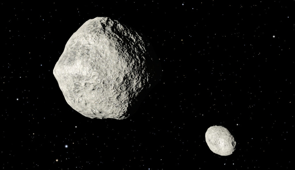
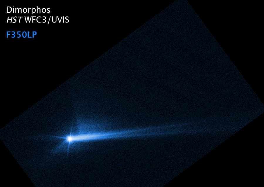
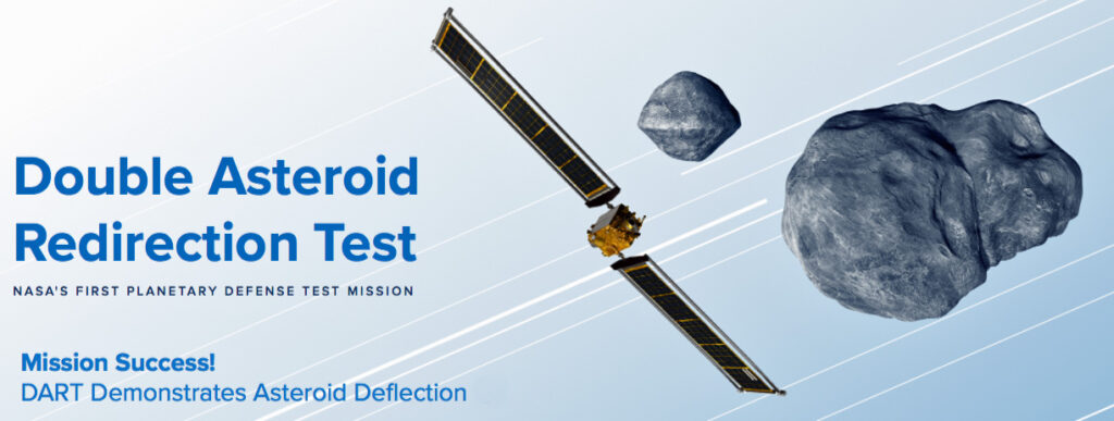
NASA’s Double Asteroid Redirection Test (DART), which was launched on 24 November 2021, was the first test of a technology for defending Earth against potential asteroid or comet hazards. DART’s target was the small “moonlet” named Dimorphos orbiting the larger near-Earth asteroid Didymos, which itself is only a half mile in diameter. You can explore at the Didymos – Dimorphos binary system on NASA’s Solar System Exploration webpage here: https://solarsystem.nasa.gov/asteroids-comets-and-meteors/asteroids/didymos/in-depth/
Simulation of the Didymos – Dimorphos binary system. Source: NASA’s Solar System Exploration
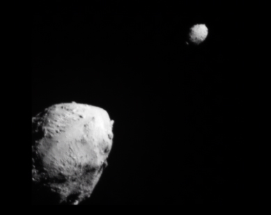
Actual view of the Didymos – Dimorphos binary system as DART approached impact with Dimorphos (background). Source: NASA / JHAPL
The goal is for the DART spacecraft was to strike the moonlet Dimorphos at high speed while being trailed by another small spacecraft, the Italian Space Agency’s (ASI) cubesat, dubbed LICIACube, that would directly observe the encounter and report back to NASA and ASI.
By comparing pre- and post-impact measurements made with powerful Earth-based and orbiting telescopes, the NASA / Johns Hopkins Applied Physics Lab (JHAPL) team could determine what changes occurred to Dimorphos’ orbit around Didymos. These results will help assess the feasibility of using a high-energy impactor as a tool for deflecting the trajectory of an asteroid, particularly one that represents a significant risk to Earth. Learn more about the DART spacecraft and its mission objectives on NASA’s Planetary Defense Coordination Office website here: https://www.nasa.gov/planetarydefense/dart/dart-news
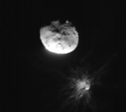
NASA successfully guided DART to a collision with Dimorphos on 26 September 2022. You can watch the final five minutes of DART’s approach to the Didymos – Dimorphos binary system up to the final image before impact here: https://www.nasa.gov/feature/dart-s-final-images-prior-to-impact
DART closeup image of Dimorphos moments before impact. Source: NASA / JHAPLASI’s LICIACube image just before its closest approach to Dimorphos (background). The debris plume cast off from Dimorphos after DART’s impact is clearly visible. Didymos is in the foreground. Source: ASI / NASA
The Hubble Space Telescope was used to capture images of the impact. The NASA/ESA Hubble Space Telescope team reported:
“The Hubble movie starts at 1.3 hours before impact. The first post-impact snapshot is 20 minutes after the event. Debris flies away from the asteroid in straight lines, moving faster than four miles per hour (fast enough to escape the asteroid’s gravitational pull, so it does not fall back onto the asteroid). The ejecta forms a largely hollow cone with long, stringy filaments.
At about 17 hours after the impact the debris pattern entered a second stage. The dynamic interaction within the binary system started to distort the cone shape of the ejecta pattern. The most prominent structures are rotating, pinwheel-shaped features. The pinwheel is tied to the gravitational pull of the companion asteroid, Didymos.
Hubble next captures the debris being swept back into a comet-like tail by the pressure of sunlight on the tiny dust particles. This stretches out into a debris train where the lightest particles travel the fastest and farthest from the asteroid. The mystery is compounded later when Hubble records the tail splitting in two for a few days.”
8 October 2022 photo by the Hubble Space Telescope shows Dimorphos with its debris tail. Source: NASA/ESA/STScI/Hubble
The results are in, and on 1 March 2023, the NASA / JHAPL team reported a much greater change to Dimorphos’ orbit than originally expected.
“…the investigation team, led by Cristina Thomas of Northern Arizona University, arrived at two consistent measurements of the period change from the kinetic impact: 33 minutes, plus or minus one minute. This large change indicates the recoil from material excavated from the asteroid and ejected into space by the impact (known as ejecta) contributed significant momentum change to the asteroid, beyond that of the DART spacecraft itself.”
Source: NASA/JHAPL
After the success of the DART mission, maybe the U.S. Planetary Defense Officer will have fewer sleepless nights, but this is only the first small, but successful step toward an operational planetary defense system.
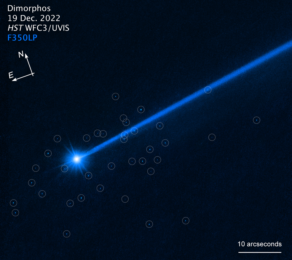
28 June 2023 update: Hubble sees bolder swarm surrounding Dimorphos
In June 2023, NASA reported that the Hubble Space Telescope had observed a swarm of 37 boulders that appears to have been knocked loose from Dimorphos upon impact.
An image of the impacted asteroid, Dimorphos, with drawn-in circles around the areas where boulders have been detected. Note that the relationship between north and east on the sky (as seen from below) is flipped relative to direction arrows on a map of the ground (as seen from above). Source: NASA, ESA, David Jewitt (UCLA); Alyssa Pagan (STScI)
NASA reported:
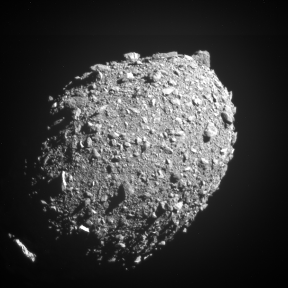
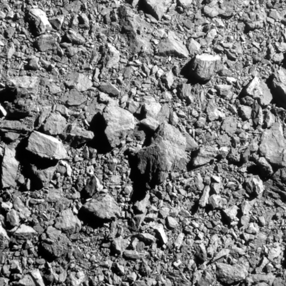
“The 37 free-flung boulders range in size from three feet to 22 feet across, based on Hubble photometry. They are drifting away from the asteroid at little more than a half-mile per hour – roughly the walking speed of a giant tortoise. The total mass in these detected boulders is about 0.1% the mass of Dimorphos…… The boulders are most likely not shattered pieces of the diminutive asteroid caused by the impact. They were already scattered across the asteroid’s surface, as evident in the last close-up picture taken by the DART spacecraft just two seconds before collision, when it was only seven miles above the surface.”
The loose composition of the surface of Dimorphos can be seen in this last complete image just prior to DART impact. Source: NASA, APL
In April 2021, I posted a short article entitled, “Multi-messenger Astronomy Provides Extraordinary Views of Uranus,” which included two composite views of Uranus, created by combining near-infrared images taken by the Keck-1 telescope at an elevation of 4,145 meters (13,599 ft) on Maunakea, Hawaii, with X-ray images taken with the Advanced CCD Imaging Spectrometer (ACIS) aboard the orbiting Chandra X-Ray Observatory.
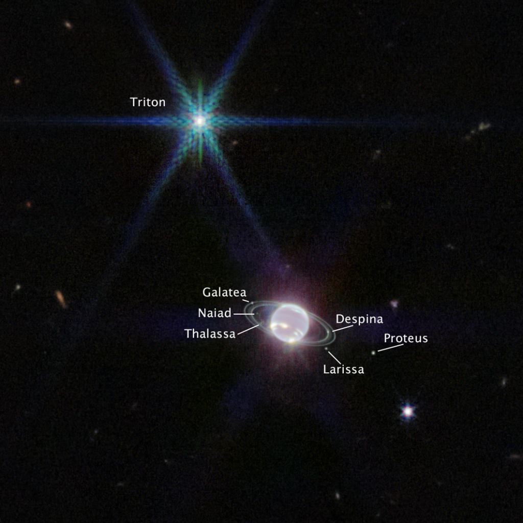
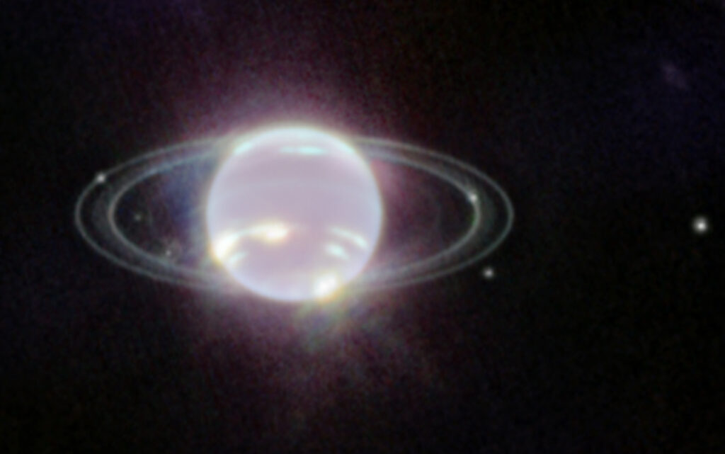
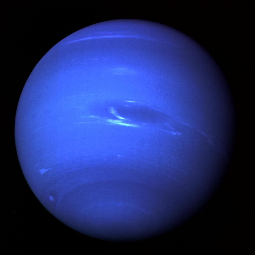
The Webb images of Neptune, taken on July 12, 2022, are reproduced below.
NASA: “Webb captured seven of Neptune’s 14 known moons: Galatea, Naiad, Thalassa, Despina, Proteus, Larissa, and Triton. Neptune’s large and unusual moon, Triton, dominates this Webb portrait of Neptune as a very bright point of light sporting the signature diffraction spikes seen in many of Webb’s images.” Source: NASA, ESA, CSA, STScINASA: “…image of Neptune……brings the planet’s rings into full focus for the first time in more than three decades. The most prominent features of Neptune’s atmosphere in this image are a series of bright patches in the planet’s southern hemisphere that represent high-altitude methane-ice clouds. More subtly, a thin line of brightness circling the planet’s equator could be a visual signature of global atmospheric circulation that powers Neptune’s winds and storms. Additionally, for the first time, Webb has teased out a continuous band of high-latitude clouds surrounding a previously-known vortex at Neptune’s southern pole.” Source: NASA, ESA, CSA, STScI
The Space Telescope Science Institute (STScI) has created a Resource Gallery of Webb Space Telescope images, which you can browse here: https://webbtelescope.org/resource-gallery/images. Currently there are 280 images in the Webb Resource Gallery. I think this is a website worth revisiting from time to time.
NASA’s Solar System Exploration website provides views of Neptune from several earlier sources, including the 1989 Voyager 2 deep space probe, the Hubble Space Telescope and the European Southern Observatory’s (ESO) Very Large Telescope (VLT). Check it out here: https://solarsystem.nasa.gov/planets/neptune/galleries/
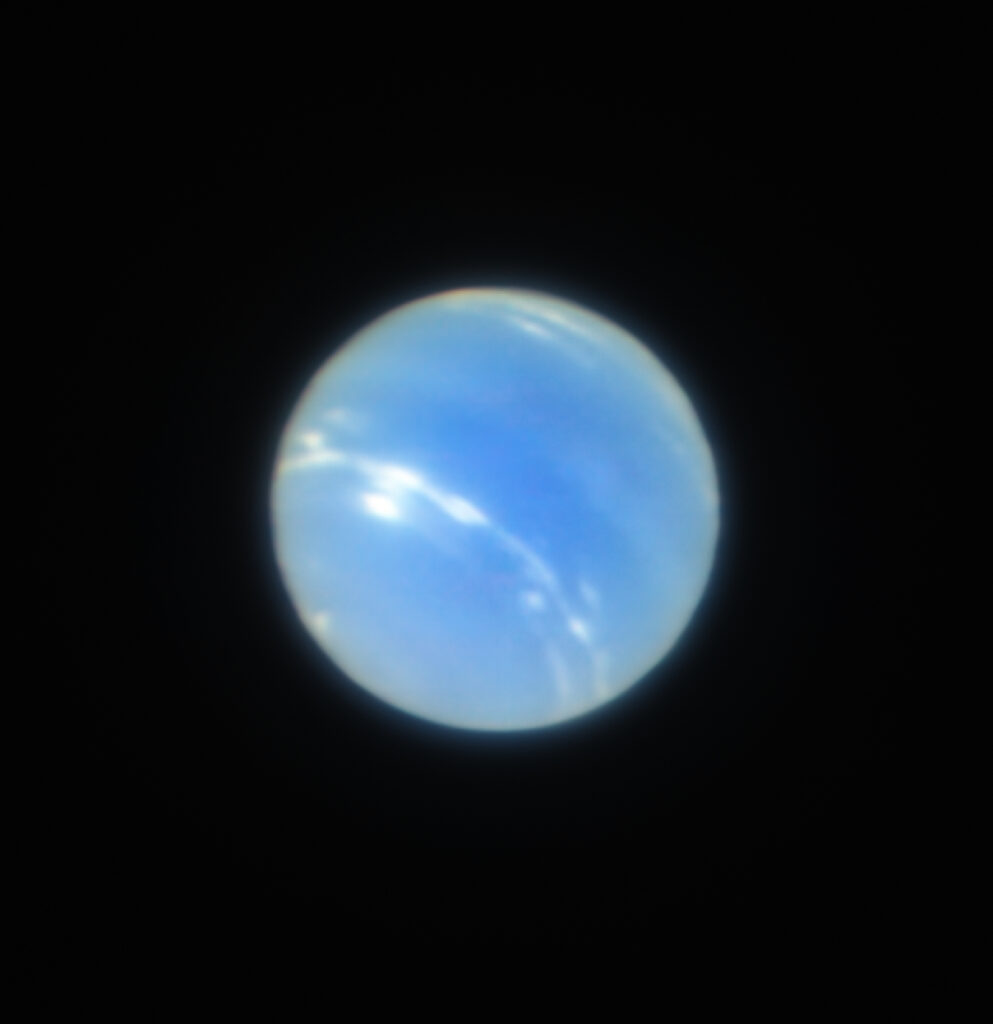
2018: The following image was taken in July 2018 during the testing of the narrow-field, adaptive optics mode of the optical/infrared MUSE/GALACSI instrument on ESO’s VLT, which is located at an elevation of 2,635 m (8,645 ft) at Cerro Paranal, in the Atacama Desert of northern Chile.
2018 VLT image of Neptune. The corrected image is sharper than a comparable image from the NASA/ESA Hubble Space Telescope. Source: ESO/P. Weilbacher (AIP)
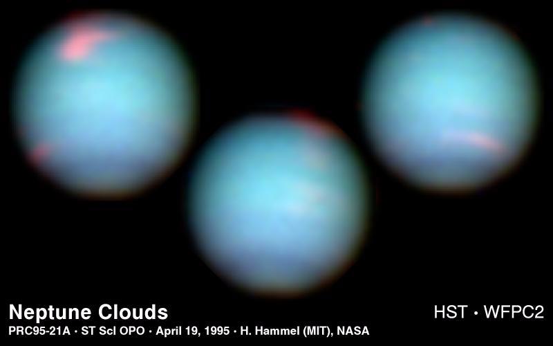
1994: The more recent Webb Space Telescope and VLT images are much better than the Hubble Space Telescope optical-range images of Neptune taken more than two decades earlier, in 1994.
NASA: “The images were taken in 1994 on October 10 (upper left), October 18 (upper right), and November 2 (lower center). Hubble is allowing astronomers to study Neptune’s dynamic atmosphere with a level of detail not possible since the 1989 flyby of the Voyager 2 space probe. Building on Voyager’s initial discoveries, Hubble is revealing that Neptune has a remarkably dynamic atmosphere that changes over just a few days. The temperature difference between Neptune’s strong internal heat source and its frigid cloud tops (-260 degrees Fahrenheit) might trigger instabilities in the atmosphere that drive these large-scale weather changes. In addition to hydrogen and helium, the main constituents, Neptune’s atmosphere is composed of methane and hydrocarbons, like ethane and acetylene.” Source: NASA, JPL, STScI
1989: In October 1989, the following whole planet view of Neptune was produced using images taken through the green and orange filters on the narrow angle camera during the Voyager 2 spacecraft flyby of the planet.
NASA: “This picture of Neptune was taken by Voyager 2 less than five days before the probe’s closest approach of the planet on Aug. 25, 1989. The picture shows the “Great Dark Spot” — a storm in Neptune’s atmosphere — and the bright, light-blue smudge of clouds that accompanies the storm”. Source: NASA/JPL-Caltech (1989)
In the future, we can hopefully look forward to more detailed multi-messenger images of Neptune, combining the near-infrared images from Webb with images from other observatories that can view the planet in different spectral bands.
It is generally assumed that all of the observable objects in our universe in composed of ordinary matter. The rationale for this assumption if explained in a 1999 Scientific American article by Steve Naftilan: https://www.scientificamerican.com/article/how-do-we-know-that-dista/
In most of the electromagnetic spectrum, a star composed of normal matter and a star composed of antimatter (anti-star) will look the same to an observer on Earth. Their visible spectra will be indistinguishable. A key difference in behavior may be observable in the gamma ray spectrum, where high-energy gamma rays characteristic of matter-antimatter annihilation (i.e., baryon-antibaryon reactions) may reveal the identity of an antimatter star within our galaxy or an antimatter star cluster outside our galaxy. Luigi Foschini provides a good introduction to this subject in his 2000 paper at the following link: https://cds.cern.ch/record/447091/files/0007180.pdf
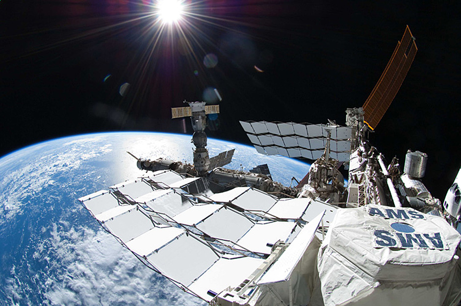
NASA’s Alpha Magnetic Spectrometer (AMS) has developed into an important tool in the search for anti-stars. The prototype, AMS-01 flew on the STS-91 Space Shuttle mission from 2 to 12 June 1998 and was successfully tested in orbit. The full-scale AMS-2 was launched aboard the STS-134 Space Shuttle mission on 16 May 2011. Since it was installed on the International Space Station (ISS) and activated on 19 May 2011, this 18,739 pound (8,500 kg), 2,250 cu. ft (64 cu meter) instrument has collected and analyzed more than 165 billion cosmic ray events (as of April 2021), and identified 9 million of these as antimatter, including the possible detection of antihelium nuclei.
You’ll find more information on AMS-1 and -2 on the NASA website here: https://ams.nasa.gov
AMS-2 installed on the ISS. Source: NASA
Another important source of data related to antimatter in our universe is NASA’s Fermi Gamma-ray Space Telescope, which was launched into a low Earth orbit on June 11, 2008. NASA’s website for the ongoing Fermi mission is here: https://fermi.gsfc.nasa.gov
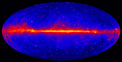
The entire sky at gamma-ray energies greater than 1 GeV based on five years of data from Fermi’s Large Area Telescope (LAT) instrument. Brighter colors indicate brighter gamma-ray sources. Source: NASA/DOE/Fermi LAT Collaboration
In an 8 February 2021 article, astrophysicist Paul Sutter postulates the existence of antimatter star clusters that escaped the primordial matter-antimatter annihilations and now exist in relative isolation, for example, as an antimatter star cluster orbiting our Milky Way galaxy.
The antimatter stars in the cluster would continuously shed antimatter into the cosmos, leading to subsequent matter-antimatter interactions that produce high-energy particles that may be detectable from Earth.
Sutter commented, “…if astronomers are able to pinpoint a globular cluster as a particularly strong source of anti-particles, it would be like opening a time capsule, giving us a window into the physics that dominated the universe when it was only a second old.”
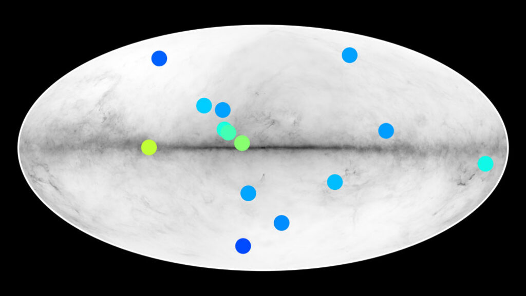
In a 20 April 2021 paper, authors Dupourqué, Tibaldo, and von Ballmoos report the possible detection of 14 anti-stars within our Milky Way galaxy. They used 10 years of data on 5,800 gamma-ray sources in Fermi’s data catalog to develop an estimate of the possible abundance of anti-stars. The authors report: “We identify in the catalog 14 anti-star candidates not associated with any objects belonging to established gamma-ray source classes and with a spectrum compatible with baryon-antibaryon annihilation.”
Fourteen celestial sources of gamma rays (colored dots in this all-sky map of the Milky Way; yellow / green indicates bright sources and blue shows dim sources) may come from stars made of antimatter. Source: Simon Dupourqué / IRAP via ScienceNews
The 14 anti-star candidates await further analysis to confirm or refute their existence. If confirmed, they represent only a small fraction of the population of all gamma-ray sources observed by the Fermi Gamma-ray Space Telescope. Nonetheless, even one confirmed anti-star would be a remarkable achievement.
For more information:
Steve Naftilan, “How do we know that distant galaxies are composed of matter rather than anti-matter? If equal quantities of each were produced in the big bang, might not some parts of the universe contain primarily matter and other parts primarily anti-matter?” Scientific American, 21 October 1999: https://www.scientificamerican.com/article/how-do-we-know-that-dista/
Simon Dupourqué, Luigi Tibaldo, and Peter von Ballmoos, “Constraints on the antistar fraction in the Solar System neighborhood from the 10-year Fermi Large Area Telescope gamma-ray source catalog,” Phys. Rev. D 103, 083016, 20 April 2021 (abstract only without subscription): https://journals.aps.org/prd/abstract/10.1103/PhysRevD.103.083016
NASA’s Perseverance rover landed on Mars on 18 February 2021 carrying an impressive suite of scientific instruments and another vehicle, the autonomous Mars helicopter Ingenuity. The Perseverance rover joins the Curiosity rover and the InSight lander, as active NASA missions on the surface of Mars. The Perseverance mission website here: https://mars.nasa.gov/mars2020/
One of the important objectives of this mission is to demonstrate that the solar-powered Ingenuity helicopter can fly in the thin atmosphere of Mars. On Earth, our standard sea level air pressure is 1,013 millibars. On Mars, the surface atmospheric pressure varies during the year, but averages between 6 to 7 millibars. That’s equivalent to an Earth pressure altitude of 88,000 to 90,600 ft (27,127 to 27,615 m). On Earth, the helicopter altitude record is 40,820 ft (12,442 m). During development, Ingenuity’s rotor system was tested in a high-altitude chamber to validate its expected performance.
Ingenuity was carried under the rover and was deployed on 3 April 2021, about six weeks after landing.
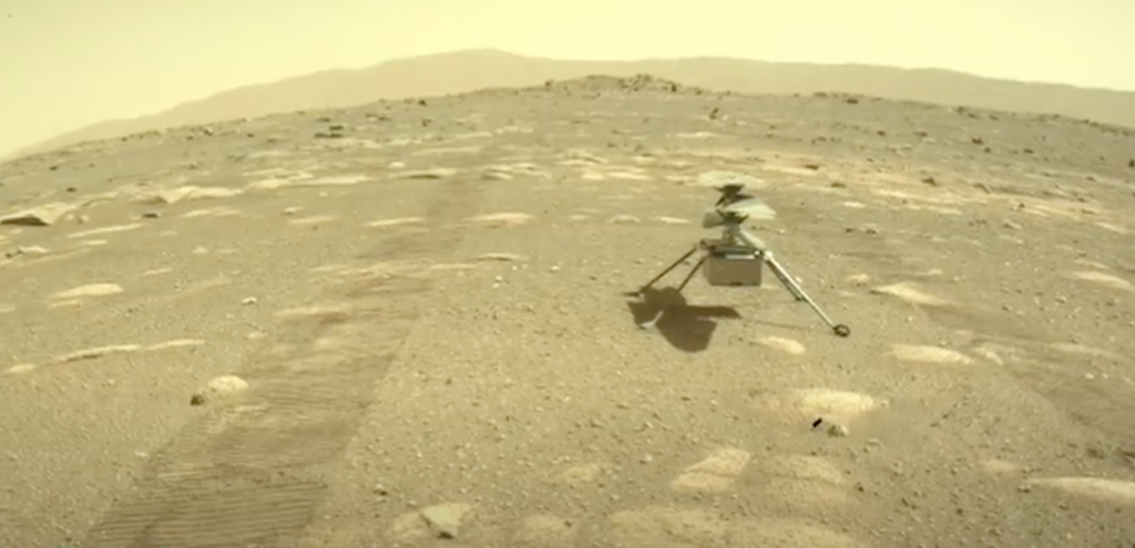
View of Ingenuity on the surface of Mars after it was deployed by the Perseverance rover. Source: NASA / JPL
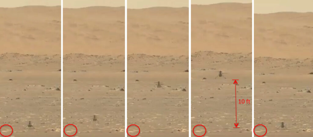
After system checkouts and software updates, Ingenuity flew for the first time on 19 April 2021, becoming the first aircraft ever to fly on Mars. The first flight took place in Jezero Crater, lasted 39 seconds, and covered a vertical distance of about 10 feet (3 m), with Ingenuity landing back at the takeoff point. For this first flight, the Perseverance rover was parked about 211 feet (64.3 meters) away and chronicled the flight operations with its cameras.
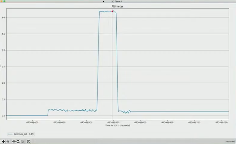
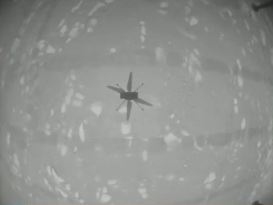
Ingenuity lifts off & rises vertically about 10 feet before landing at the takeoff point. Use the red-circled rock as a common point of reference in each frame. Source: Screenshots from NASA video.Ingenuity altimeter data confirmed the first flight. Source: Screenshot from NASA video.Shadow on the ground of Ingenuity in flight, taken from its own downward-looking navigation camera. Source: Screenshot from NASA video.
A longer (47:20 minute) video from NASA Mission Control is here:
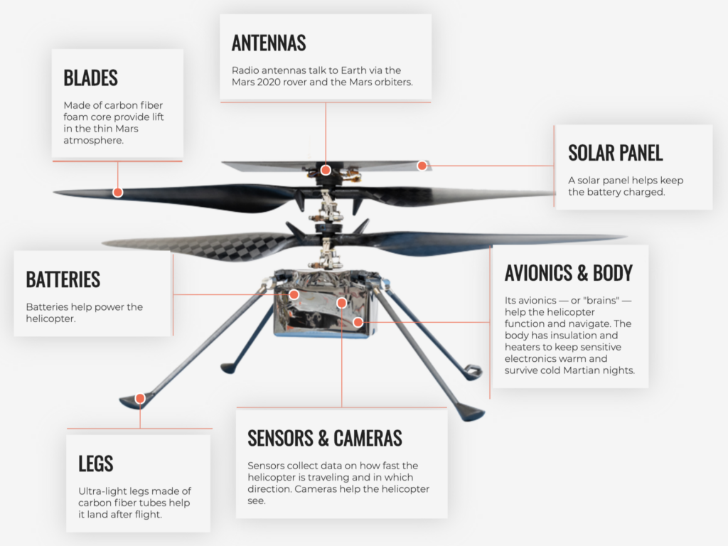
The Mars helicopter was conceived as a 30-day technology demonstration. To meet the weight and space budgets allocated for the Mars Helicopter, Ingenuity had to be a very compact, lightweight flying machine. The 1.8 kg (4.0 lb) mini-copter flies with two electric motor driven, counter-rotating, coaxial rotors about 1.1 m (3 ft 7 in) in diameter. The rotors are powered from a rechargeable 2 Ah (Amp-hour) lithium-ion battery. This is similar to the battery capacity of many cell phones. The general arrangement of the Ingenuity Mars helicopter is shown in the following diagram.
Uranus, the seventh planet from the Sun, is an ice giant planet with 27 known moons in a unique orbit beyond Saturn. Uranus makes a complete orbit around the Sun in about 84 Earth years. It is the only planet whose equator is tilted nearly at a right angle to its orbital plane, which results in the polar regions pointing toward the Sun (and Earth) during parts of the orbit.
Uranus was visited briefly by NASA’s Voyager 2 spacecraft during its January 1986 flyby, which came within 81,500 km (50,600 miles) of the planet’s cloud tops. Since then, Uranus has been studied at visible, near-infrared and X-ray wavelengths from the perspective of terrestrial and near-Earth, space-based observatories.
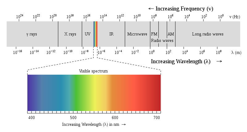
Visible light has a wavelength in the range from about 350 to 750 nanometers (nm, 10-9meters) or 3,500 to 7,500 Angstroms. Near-infrared light is the part of the infrared spectrum that is closest to the visible light spectrum, but at a longer wavelength, from about 800 to 2,500 nm. X-rays have a much shorter wavelength, from about 20 to 0.001 nm. In the following chart, you can see the relative placement of visible and near-infrared light and X-rays in the electromagnetic spectrum.
Electromagnetic spectrum. Source: Wikipedia
2. 2021 composite images of Uranus at visible / near-infrared and X-ray wavelengths
In March 2021, the National Aeronautics and Space Administration (NASA) announced that its orbiting Chandra X-ray Observatory had made the first ever detection of X-rays coming from the ice giant planet Uranus. Recent analysis of Chandra observations from 2002 and 2017 resulted in this discovery. You can read NASA’s 2021 announcement of this discovery here: https://chandra.si.edu/photo/2021/uranus/
X-rays coming from other planets have been detected in the past. NASA reported, “Like Jupiter and Saturn, Uranus and its rings appear to mainly produce X-rays by scattering solar X-rays, but some may also come from auroras…… The X-rays from auroras on Jupiter come from two sources: electrons traveling down magnetic field lines, as on Earth, and positively charged atoms and molecules raining down at Jupiter’s polar regions. However, scientists are less certain about what causes auroras on Uranus.”
Another possible X-ray source could be from an interaction between Uranus’ rings and the near-space charged particle environment around the planet. This phenomenon has been observed at Saturn.
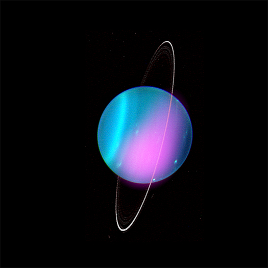
In connection with the discovery of X-rays coming from Uranus, NASA released two spectacular composite (multi-messenger) images of the planet created by combining images from two different parts of the electromagnetic spectrum: optical / near-infrared and X-ray.
The components of the first composite image are described below:
Near-infrared image: This was taken in July 2004 with the 10-meter (32-foot 10-inch) Keck-1 telescope located at an altitude of 4,145 meters (13,599 ft) on Maunakea, Hawaii.
The X-ray image: This was produced with 7 August 2002 data from the Advanced CCD Imaging Spectrometer (ACIS) aboard Chandra, which has a spatial resolution of 0.5” (seconds). The angular size of Uranus for the observation was 3.7”. The X-rays were in the 0.6 to 1.1 keV (2.1 to 1.1 nm) spectral range, which is consistent with X-ray emissions from Jupiter and Saturn.
(Left) Keck-1 July 2004 near-infrared image of Uranus. The North Pole is at the 4 o’clock position. Sources: Space Science Institute; University of Wisconsin-Madison / W. M. Keck Observatory (Right) Chandra August 2002 ACIS X-ray image of Uranus. Sources: NASA/CXO/University College London
2021 Keck-1 & Chandra ACIS composite image
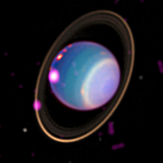
The second 2021 composite image, shown below, was created from a Keck optical image and X-ray images made with Chandra’s High Resolution Camera (HRC) during observations on 11 and 12 November 2017. The HRC is sensitive to softer X-ray emissions (down to 0.06 keV, 20.7 nm) than ACIS, enabling it to collect more photons in the 0.1–1.2 keV (12.4 to 0.1 nm) range most important for planetary studies. The authors report, ”These fluxes exceed expectations from scattered solar emission alone, suggesting either a larger X-ray albedo than Jupiter/Saturn or the possibility of additional X-ray production processes at Uranus.”
2021 Keck & Chandra HRC composite image Sources: X-ray: NASA/CXO/University College London/W. Dunn et al; Optical: W.M. Keck Observatory
The authors conclude by noting that, “Further, and longer, observations with Chandra would help to produce a map of X-ray emission across Uranus and to identify, with better signal-to-noise, the source locations for the X-rays, constraining possible contributions from the rings and aurora…… However, the current generation of X-ray observatories does not provide sufficient sensitivity to spectrally characterize the short interval temporal fluctuation observed in the November 12, 2017 observation.”
New space-based X-ray observational capabilities are being developed by NASA and the European Space Agency (ESA), but won’t be operational for a decade or more:
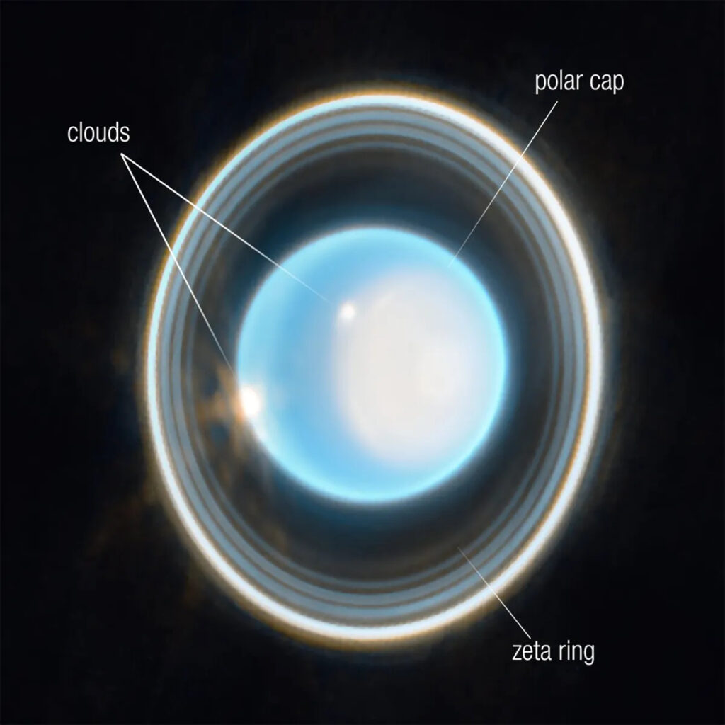
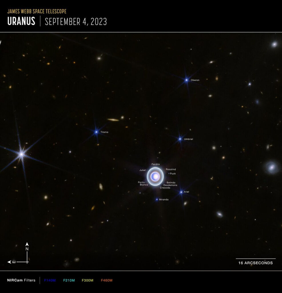
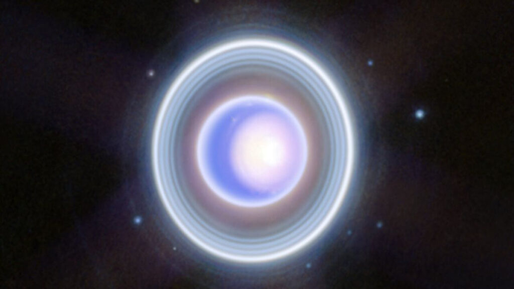
The James Webb Space Telescope (JWST), which has four science instruments designed to observe at optical to mid-infrared (0.6 – 28.3 microns) wavelengths, produced its first images of Uranus in April 2023.
Annotated image of Uranus captured by the JWST on 6 Feb. 2023, provides a view of the bright North polar ice cap and glowing clouds at near-infrared wavelengths of 1.4 to 3.0 microns.Sources: NASA, ESA, CSA, STScI
Wide field image of Uranus captured by the JWST on 6 Feb. 2023 at near-infrared wavelengths of 1.4 to 5.0 microns. Note that 14 of the 27 known moons are identified in the image. Also note the many distant galaxies in this image. Sources: NASA, ESA, CSA, STScI
Enlarged view of the 6 Feb. 2023 JWST near-infrared image shows the bright North polar cap, glowing clouds, details of the ring structure and many of the inner moons. Sources: NASA, ESA, CSA, STScI
4. 2025 JWST maps Uranus upper atmosphere
ESA scientists used the JWST Near-Infrared Spectrograph (NIRSpec) to map the temperature and ion density across the planet through almost one full rotation of the planet (15 hours of one 17 hour rotation). ESA reported that the NIRSpec measurements found that the highest recorded temperatures occurred between 3,000 to 4,000 kilometers (1,864 to 2,485 miles) above the cloud tops, while the highest ion densities, appearing as auroral bands, were much lower, at around 1,000 kilometers (621 miles), revealing clear longitudinal variations linked to the complex geometry of the magnetic field.
JWST still frames show Uranus through almost an entire rotation of the planet. Source: ESA (January 2025)
You can watch a short time-lapse video of JWST images showing the movement of the auroral bands around the planet for almost one full rotation here.
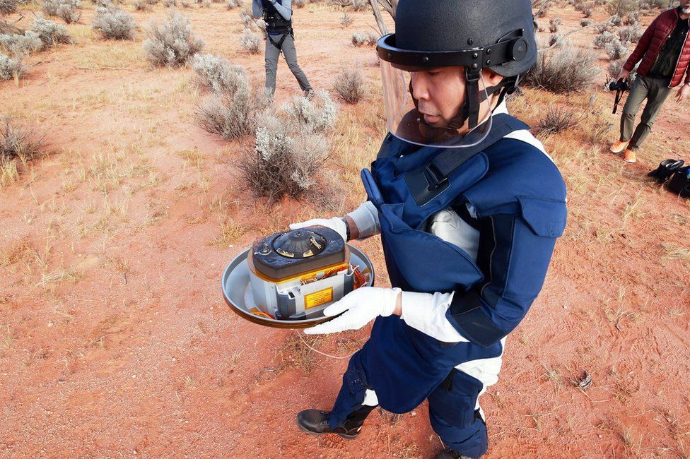
Japan’s Hayabusa2 (Japanese for Peregrine falcon 2) spacecraft returned from its six-year mission to asteroid 162173 Ryugu for a high-speed fly-by of Earth on 5 December 2020, during which it released a reentry capsule containing the material collected during two separate sampling visits to the asteroid’s surface. The capsule successfully reentered Earth’s atmosphere, landed in the planned target area in Australia’s Woomera Range and was recovered intact. The sample return capsule is known as the “tamatebako” (treasure box).
Location of Woomera Range. Source: itea.org
Hayabusa2’s sample return capsule after landing in the Woomera Range, Australia. Source: JAXACapsule containing samples from asteroid Ryugu. Source: JAXA
Background
The first asteroid sample return mission was Japan’s Hayabusa1, which was launched on 9 May 2003 and rendezvoused with S-type asteroid 25143 Itokawa in mid-September 2005. A small sample was retrieved from the surface on 25 November 2005. The sample, comprised of tiny grains of asteroidal material, was returned to Earth on 13 June 2010, with a landing in the Woomera Range.
Japan’s Hayabusa2 and the US OSIRIS-Rex asteroid sample return missions overlap, with Hayabusa2 launching about two years earlier and returning its surface samples almost three years earlier. Both spacecraft were orbiting their respective asteroids from 31 December 2018 to 12 November 2019.
You’ll find a great deal of information and current news on the Hayabusa2 and OSIRIS-REx asteroid sample return missions on their respective project website:
An extended mission to explore additional asteroids was made possible by the excellent health of the Hayabusa2 spacecraft and the economic use of fuel during the basic mission. Hayabusa2 still has 30 kg (66 lb) of xenon propellant for its ion engines, about half of its initial load of 66 kg (146 lb).
As of September 2020, JAXA’s plans are is to target the Hayabusa2 spacecraft for the following two asteroid encounters:
Conduct a high-speed fly-by of L-type asteroid (98943) 2001 CC21 in July 2026. This asteroid has a diameter between 3.47 to 15.52 kilometers (2.2 to 9.6 miles).
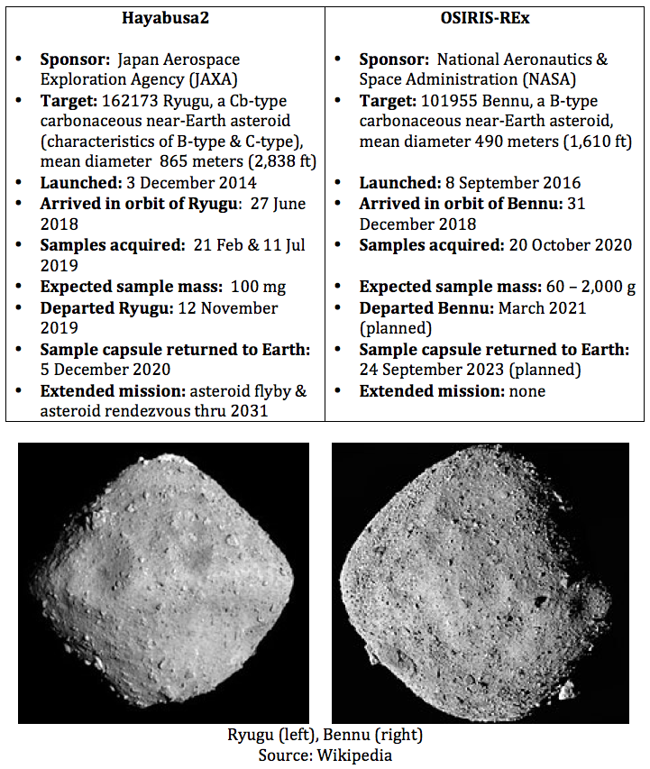
Continue on a rendezvous with asteroid 1998 KY26 in July 2031. This is a 30-meter (98-foot) diameter asteroid, potentially X-type (metallic), and rotating rapidly with a period of only 10.7 minutes.
Computer model view of 1998 KY26 based on radar data from Goldstone observatory. Source: NASA/JPL via Wikipedia
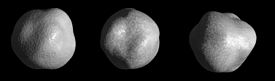
On 20 April 2020, the U.S. Geological Survey (USGS) released the first-ever comprehensive digital geologic map of the Moon. The USGS described this high-resolution map as follows:
“The lunar map, called the ‘Unified Geologic Map of the Moon,’ will serve as the definitive blueprint of the moon’s surface geology for future human missions and will be invaluable for the international scientific community, educators and the public-at-large.”
Color-coded orthographic projections of the “Unified Geologic Map of the Moon” showing the geology of the Moon’s near side (left) and far side (right). Source: NASA/GSFC/USGS
This remarkable mapping product is the culmination of a decades-long project that started with the synthesis of six Apollo-era (late 1960s – 1970s) regional geologic maps that had been individually digitized and released in 2013 but not integrated into a single, consistent lunar map.
This intermediate mapping product was updated based on data from the following more recent lunar satellite missions:
The Lunar Reconnaissance Orbiter Camera (LROC) is a system of three cameras that capture high resolution black and white images and moderate resolution multi-spectral images of the lunar surface: http://lroc.sese.asu.edu
Topography for the north and south poles was supplemented with Lunar Orbiter Laser Altimeter (LOLA) data: https://lola.gsfc.nasa.gov
The final product is a seamless, globally consistent map that is available in several formats: geographic information system (GIS) format at 1:5,000,000-scale, PDF format at 1:10,000,000-scale, and jpeg format.
At the following link, you can download a large zip file (310 Mb) that contains a jpeg file (>24 Mb) with a Mercator projection of the lunar surface between 57°N and 57°S latitude, two polar stereographic projections of the polar regions from 55°N and 55°S latitudes to the poles, and a description of the symbols and color coding used in the maps.
These high-resolution maps are great for exploring the lunar surface in detail. A low-resolution copy (not suitable for browsing) is reproduced below.
For more information on the Unified Geologic Map of the Moon, refer to the paper by C. M. Fortezzo, et al., “Release of the digital Unified Global Geologic Map of the Moon at 1:5,000,000-scale,” which is available here: https://www.hou.usra.edu/meetings/lpsc2020/pdf/2760.pdf
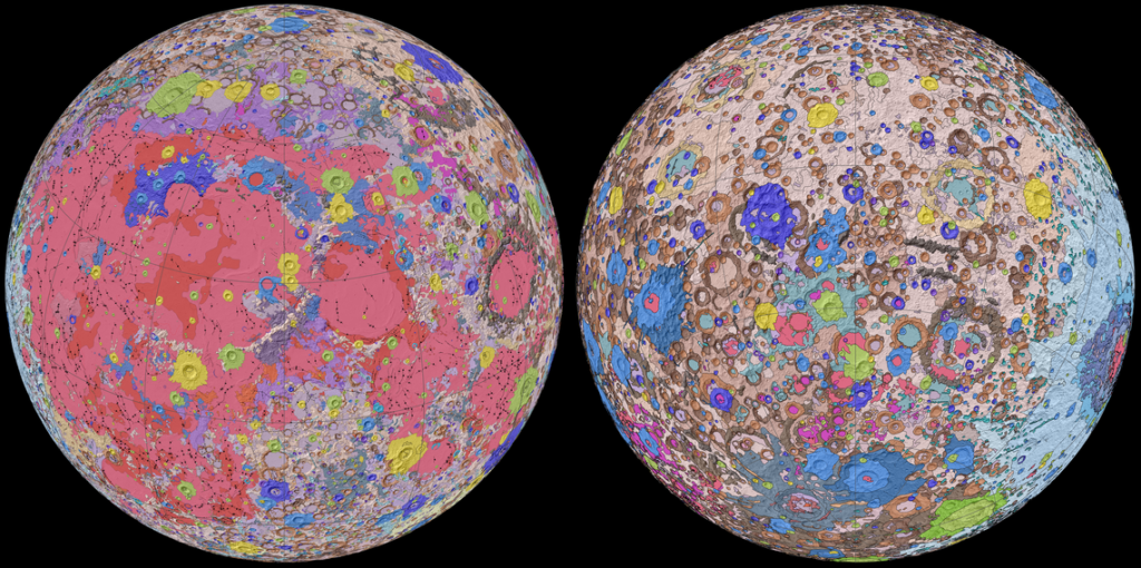
On July 16th, 1969, 13:32:00 UTC, the Saturn V launch vehicle, SA-506, lifted off from Launch Pad 39-A at Kennedy Space Center, Florida on the Apollo 11 mission with astronauts Neil Armstrong (Mission commander), Michael Collins (Command Module pilot) and Edwin (Buzz) Aldrin (Lunar Module pilot).
L to R: Neil Armstrong, Michael Collins & Buzz Aldrin. Source: NASA
Apollo 11 insignia: Eagle with wings outstretched holding an olive branch above the Moon with Earth in the background.Source: NASA via Wikipedia
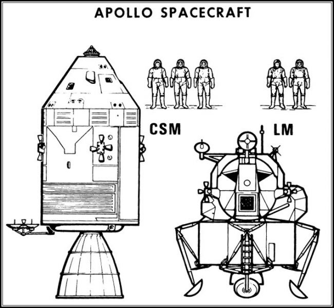
The Apollo spacecraft consisted of three modules:
The three-person Command Module (CM), named Columbia, was the living quarters for the three-person crew during most of the lunar landing mission.
The Service Module (SM) contained the propulsion system, electrical fuel cells, consumables storage tanks (oxygen, hydrogen) and various service / support systems.
The two-person, two-stage Lunar Module (LM), named Eagle, would make the Moon landing with two astronauts and return them to the CM.
The LM’s descent stage (bottom part of the LM with the landing legs) remained on the lunar surface and served as the launch pad for the ascent stage (upper part of the LM with the crew compartment). Only the 4.9 ton CM was designed to withstand Earth reentry conditions and return the astronauts safely to Earth.
General configuration of the Apollo spacecraft. The “CSM” is the combined Command Module and Service Module. Source: NASA
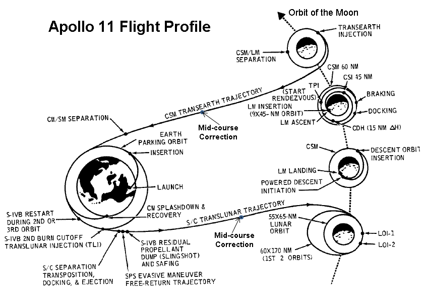
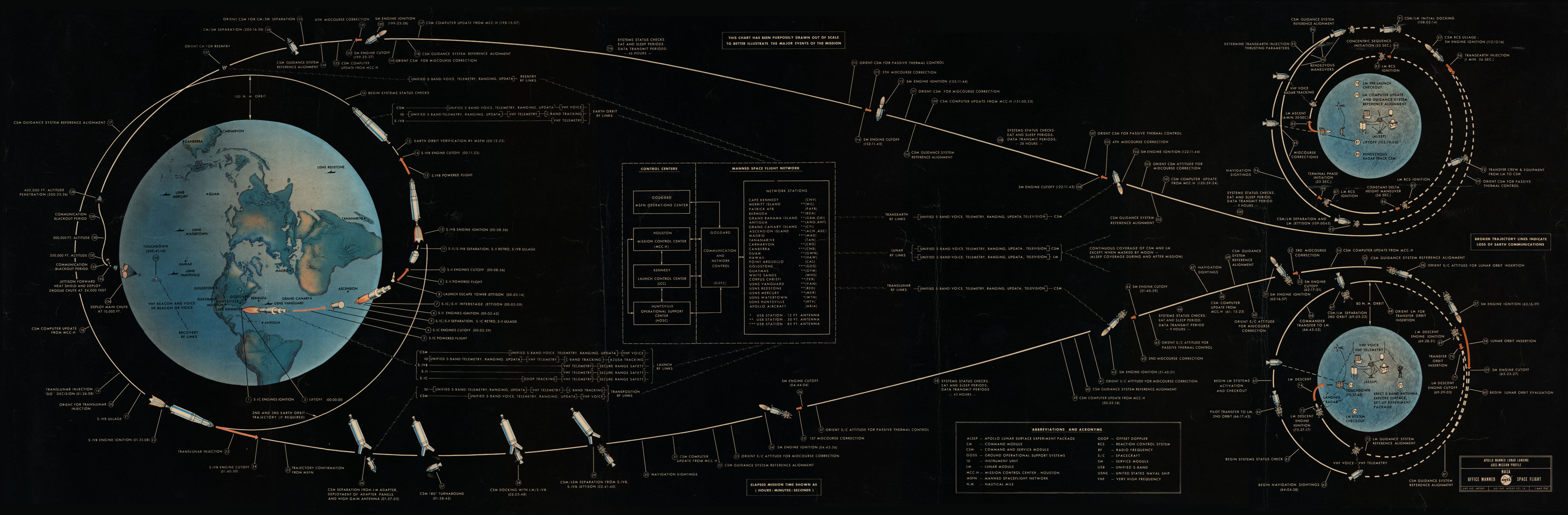
From its initial low Earth parking orbit, Apollo 11 flew a direct trans-lunar trajectory to the Moon, inserting into lunar orbit about 76 hours after liftoff. The Apollo 11 mission profile to and from the Moon is shown in the following diagram, and is described in detail here: https://www.mpoweruk.com/Apollo_Moon_Shot.htm
Source: NASA
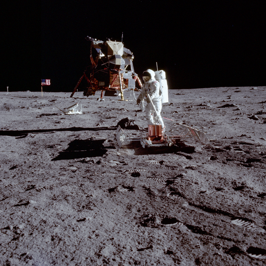
Neil Armstrong and Buzz Aldrin landed the Eagle LM in the Sea of Tranquility on 20 July 1969, at 20:17 UTC (about 103 hours elapsed time since launch), while Michael Collins remained in a near-circular lunar orbit aboard the CSM. Neil Armstrong characterized the lunar surface at the Tranquility Base landing site with the observation, “it has a stark beauty all its own.”
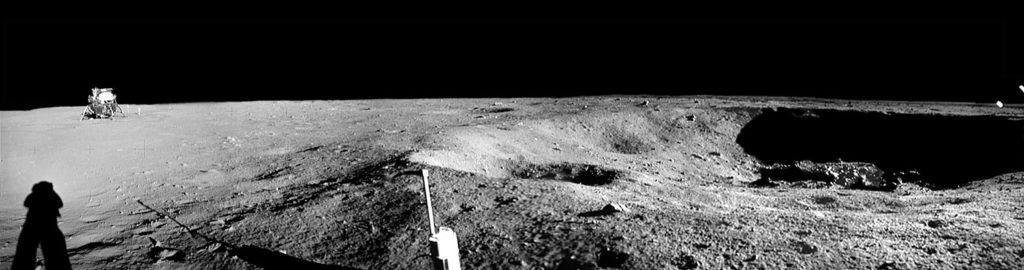
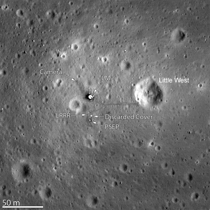
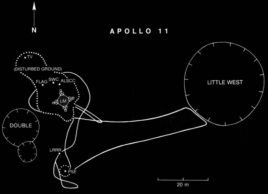
In the two and a half hours they spent on the lunar surface, Armstrong and Aldrin collected 21.55 kg (47.51 lb) of rock samples, took photographs and set up the Passive Seismic Experiment Package (PSEP) and the Laser Ranging RetroReflector (LRRR), which would be left behind on the Moon. The PSEP provided the first lunar seismic data, returning data for three weeks after the astronauts left, and the LRRR allows precise distance measurements to be collected to this day. Neil Armstrong made an unscheduled jaunt to Little West crater, about 50 m (164 feet) east of the LM, and provided the first view into a lunar crater.
Apollo 11 PSEP in the foreground with astronaut Buzz Aldrin and the LRRR behind it, then the Eagle LM, the American flag, and the TV camera on the left horizon beyond the American flag. Source: NASANeil Armstrong’s photo showing the Eagle LM from Little West crater (33 meters in diameter). Source: NASAApollo 11 landing site captured from 24 km (15 miles) above the surface by NASA’s Lunar Reconnaissance Orbiter (LRO). Source: adapted from NASA Goddard/Arizona State UniversityApollo 11 “traverse” map. Source: NASA via Smithsonian https://airandspace.si.edu/
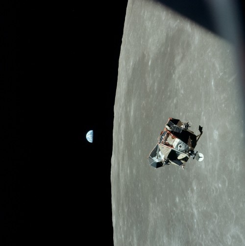
Armstrong and Aldrin departed the Moon on 21 July 1969 at 17:54 UTC in the ascent stage of the Eagle LM and then rendezvoused and docked with Collins in the CSM about 3-1/2 hours later.
LM Eagle ascent stage with Armstrong and Aldrin approaching the CSM Columbia piloted by Collins. Source: NASA
After discarding the ascent stage, the CSM main engine was fired and Apollo 11 left lunar orbit on 22 July 1969 at 04:55:42 UTC and began its trans-Earth trajectory. As the Apollo spacecraft approached Earth, the SM was jettisoned.
The CM reentered the Earth’s atmosphere and landed in the North Pacific on 24 July 1969 at 16:50:35 UTC. The astronauts and the Apollo 11 spacecraft were recovered by the aircraft carrier USS Hornet. President Nixon personally visited and congratulated the astronauts while they were still in quarantine aboard the USS Hornet. You can watch a video of this meeting here:
Mankind’s first lunar landing mission was a great success.
Postscript to the first Moon landing
A month after returning to Earth, the Apollo 11 astronauts were given a ticker tape parade in New York City, then termed as the largest such parade in the city’s history.
New York City ticker tape parade for the Apollo 11 astronauts. Source: NASA / Bill Taub
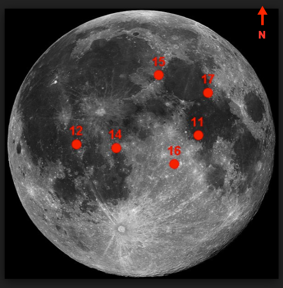
There were a total of six Apollo lunar landings (Apollo 11, 12, 14, 15, 16, and 17), with the last mission, Apollo 17, returning to Earth on 19 December 1972. Their landing sites are shown in the following graphic.
The Apollo landing sites. Source: NASA
In the past 46+ years since Apollo 17, there have been no manned missions to the Moon by the U.S. or any other nation.
Along with astronaut John Glenn, the first American to fly in Earth orbit, the three Apollo 11 astronauts were awarded the New Frontier Congressional Gold Medal in the Capitol Rotunda on 16 November 2011. This is the Congress’ highest civilian award and expression of national appreciation for distinguished achievements and contributions.
Neil Armstrong died on 25 August 2012 at the age of 82.
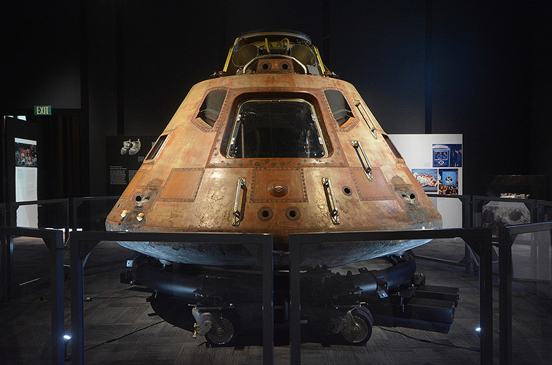
The Apollo 11 command module Columbia was physically transferred to the Smithsonian Institution in 1971 and has been on display for decades at the National Air and Space Museum on the mall in Washington D.C. For the 50th anniversary of the Apollo 11 mission, Columbia will be on display at The Museum of Flight in Seattle, as the star of the Smithsonian Institution’s traveling exhibition, “Destination Moon: The Apollo 11 Mission.” You can get a look at this exhibit at the following link: http://www.collectspace.com/news/news-041319a-destination-moon-seattle-apollo.html
The Apollo 11 command module Columbia at The Museum of Flight in Seattle. Source: collectSPACE
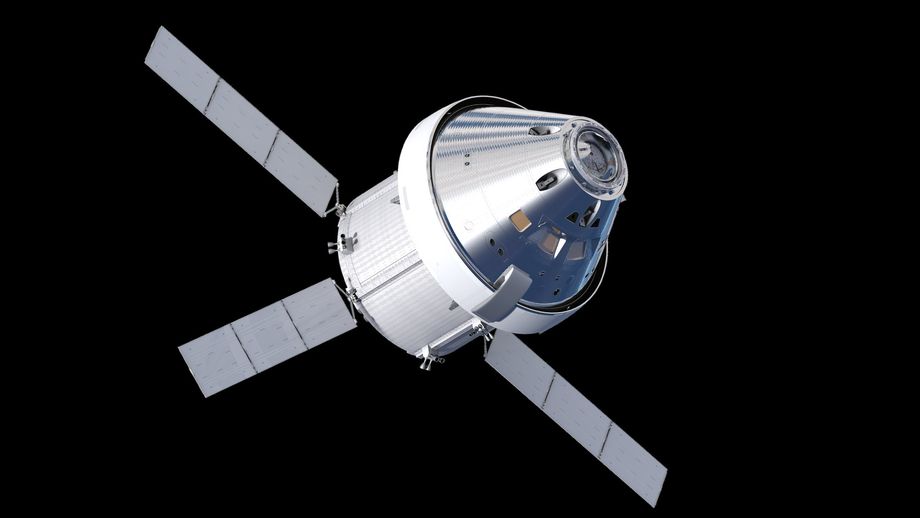
After years of changing priorities under the Bush and Obama administrations, NASA’s current vision for the next U.S. manned lunar landing mission is named Artemis, after the Greek goddess of hunting and twin sister of Apollo. NASA currently is developing the following spaceflight systems for the Artemis mission:
The Space Launch System (SLS) heavy launch vehicle.
A manned “Gateway” station that will be placed in lunar orbit, where it will serve as a transportation node for lunar landing vehicles and manned spacecraft for deep space missions.
The Orion multi-purpose manned spacecraft, which will deliver astronauts from Earth to the Gateway, and also can be configured for deep space missions.
Lunar landing vehicles, which will shuttle between the Gateway and destinations on the lunar surface.
The Orion spacecraft is functionally comparable to the Apollo command and service modules. Source: NASA
While NASA has a tentative goal of returning humans to the Moon by 2024, the development schedules for the necessary Artemis systems may not be able to meet this ambitious schedule. The landing site for the Artemis mission will be in the Moon’s south polar region. NASA administrator Jim Bridenstine has stated that Artemis will deliver the first woman to the Moon.
Robert C. Seamens, Jr., “Project Apollo – The Tough Decisions,” NASA Monographs in Aerospace History Number 37, NASA SP-2007-4537, 2007; https://history.nasa.gov/monograph37.pdf
Ian A. Crawford, “The Scientific Legacy of Apollo,” Astronomy and Geophysics (Vol. 53, pp. 6.24-6.28), December 2012; https://arxiv.org/pdf/1211.6768.pdf
Roger D. Launis, “Apollo’s Legacy: Perspectives on the Moon Landings,” Smithsonian Books, 14 May 2019, ISBN-13: 978-1588346490
Neil Armstrong, Michael Collins & Edwin Aldrin, “First on the Moon,” William Konecky Assoc., 15 October 2002, ISBN-13: 978-1568523989
Michael Collins, “Flying to the Moon: An Astronaut’s Story,” Farrar, Straus and Giroux (BYR); 3 edition, 28 May 2019, ISBN-13: 978-0374312022
Michael Collins, “Carrying the Fire: An Astronaut’s Journeys: 50th Anniversary Edition Anniversary Edition,” Farrar, Straus and Giroux, 16 April 2019, ISBN-13: 978-0374537760
Edwin Aldrin, “Return to Earth,” Random House; 1st edition, 1973, ISBN-13: 978-0394488325
After the failure of Israel’s Beresheet spacecraft to execute a soft landing on the Moon in April 2019, India is the next new contender for lunar soft landing honors with their Chandrayaan-2 spacecraft. We’ll take a look at the Chandrayaan-2 mission in this post.
1. Background: India’s Chandrayaan-1 mission to the Moon
India’s first mission to the Moon, Chandrayaan-1, was a mapping mission designed to operate in a circular (selenocentric) polar orbit at an altitude of 100 km (62 mi). The Chandrayaan-1 spacecraft, which had an initial mass of 1,380 kg (3,040 lb), consisted of two modules, an orbiter and a Moon Impact Probe (MIP). Chandrayaan-1 carried 11 scientific instruments for chemical, mineralogical and photo-geologic mapping of the Moon. The spacecraft was built in India by the Indian Space Research Organization (ISRO), and included instruments from the USA, UK, Germany, Sweden and Bulgaria.
Chandrayaan-1 was launched on 22 October 2008 from the Satish Dhawan Space Center (SDSC) in Sriharikota on an “extended” version of the indigenous Polar Satellite Launch Vehicle designated PSLV-XL. Initially, the spacecraft was placed into a highly elliptical geostationary transfer orbit (GTO), and was sent to the Moon in a series of orbit-increasing maneuvers around the Earth over a period of 21 days. A lunar transfer maneuver enabled the Chandrayaan-1 spacecraft to be captured by lunar gravity and then maneuvered to the intended lunar mapping orbit. This is similar to the five-week orbital transfer process used by Israel’s Bersheet lunar spacecraft to move from an initial GTO to a lunar circular orbit.
The goal of MIP was to make detailed measurements during descent using three instruments: a radar altimeter, a visible imaging camera, and a mass spectrometer known as Chandra’s Altitudinal Composition Explorer (CHACE), which directly sampled the Moon’s tenuous gaseous atmosphere throughout the descent. On 14 November 2008, the 34 kg (75 lb) MIP separated from the orbiter and descended for 25 minutes while transmitting data back to the orbiter. MIP’s mission ended with the expected hard landing in the South Pole region near Shackelton crater at 85 degrees south latitude.
In May 2009, controllers raised the orbit to 200 km (124 miles) and the orbiter mission continued until 28 August 2009, when communications with Earth ground stations were lost. The spacecraft was “found” in 2017 by NASA ground-based radar, still in its 200 km orbit.
Numerous reports have been published describing the detection by the Chandrayaan-1 mission of water in the top layers of the lunar regolith. The data from CHACE produced a lunar atmosphere profile from orbit down to the surface, and may have detected trace quantities of water in the atmosphere. You’ll find more information on the Chandrayaan-1 mission at the following links:
2. India’s upcoming Chandrayaan-2 mission to the Moon
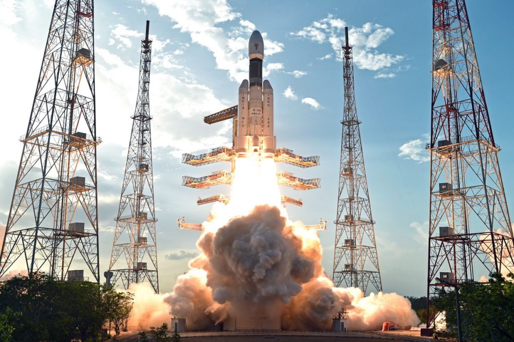
Chandrayaan-2 was launched on 22 July 2019. After achieving a 100 km (62 mile) circular polar orbit around the Moon, a lander module will separate from the orbiting spacecraft and descend to the lunar surface for a soft landing, which currently is expected to occur in September 2019, after a seven-week journey to the Moon. The target landing area is in the Moon’s southern polar region, where no lunar lander has operated before. A small rover vehicle will be deployed from the lander to conduct a 14-day mission on the lunar surface. The orbiting spacecraft is designed to conduct a one-year mapping mission.
Artist’s illustration of India’s lunar lander and the small rover vehicle on the surface of the moon. Source: ISRO
The launch vehicle
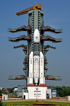
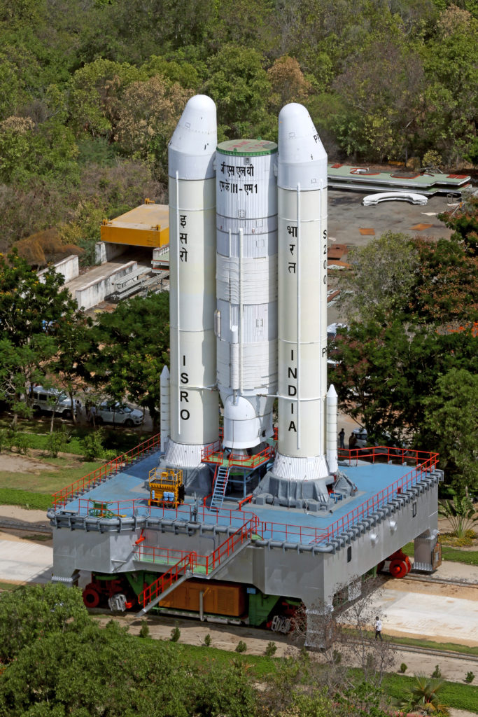
India will launch Chandrayaan-2 using the medium-lift Geosynchronous Satellite Launch Vehicle Mark III (GSLV Mk III) developed and manufactured by ISRO. As its name implies, GSLV Mk III was developed primarily to launch communication satellites into geostationary orbit. Variants of this launch vehicle also are used for science missions and a human-rated version is being developed to serve as the launch vehicle for the Indian Human Spaceflight Program.
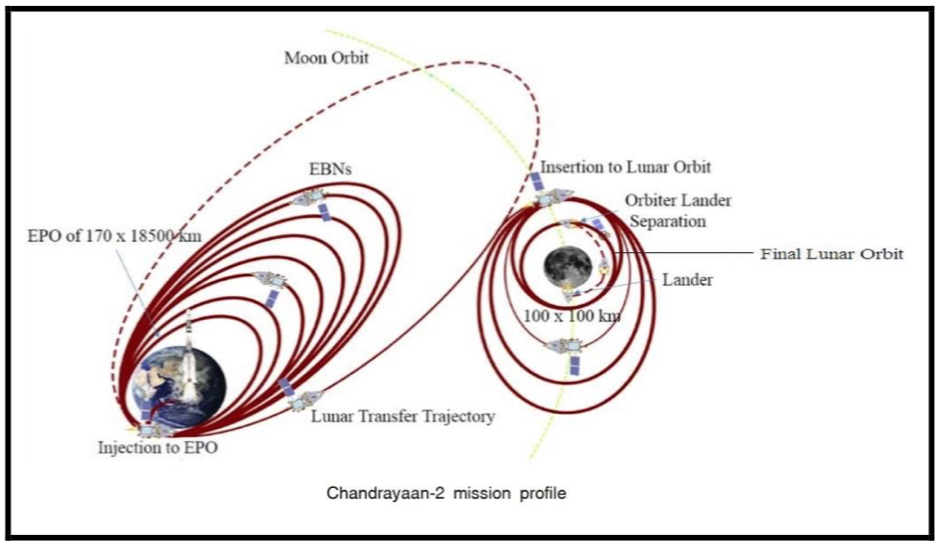
The GSLV III launch vehicle will place the Chandrayaan-2 spacecraft into an elliptical parking orbit (EPO) from which the spacecraft will execute orbital transfer maneuvers comparable to those successfully executed by Chandrayaan-1 on its way to lunar orbit in 2008. The Chandrayaan-2 mission profile is shown in the following graphic. You’ll find more information on the GSLV Mk III on the ISRO website at the following link: https://www.isro.gov.in/launchers/gslv-mk-iii
Source: ISRO
GSLV Mk III D2 on the launch pad at SDSC for the launchof the GSAT-29 communications satellite in 2018.Source: ISRO via Wikipedia
GSLV Mk III D1 lifting off from the SDSCwith the GSAT-19 communications satellite in 2017.Source: ISRO via WikipediaTransporting the partially integrated GSLV MkIII M1 launch vehicle for the Chandrayaan-2 mission on the Mobile Launch Pedestal. Source: ISRO
The spacecraft
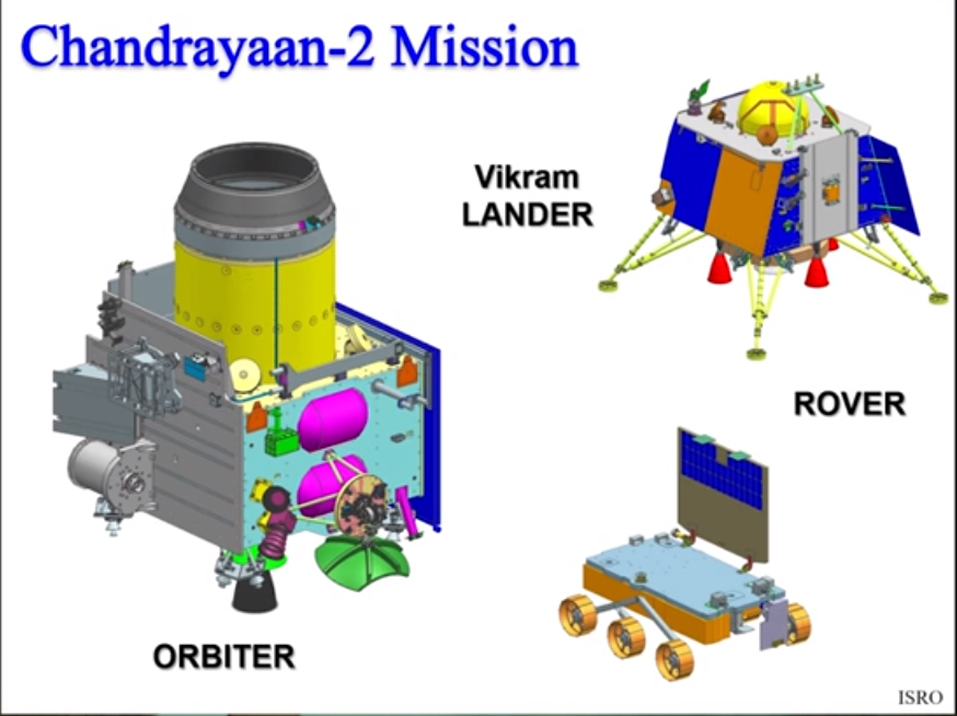
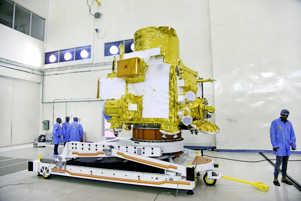
Chandrayaan-2 builds on the design and operating experience from the previous Chandrayaan-1 mission. The new spacecraft developed by ISRO has an initial mass of 3,877 kg (8,547 lb). It consists of three modules: an Orbiter Craft (OC) module, the Vikram Lander Craft (LC) module, and the small Pragyan rover vehicle, which is carried by the LC. The three modules are shown in the following diagram.
Three spacecraft modules (not to scale). Source: ISRO
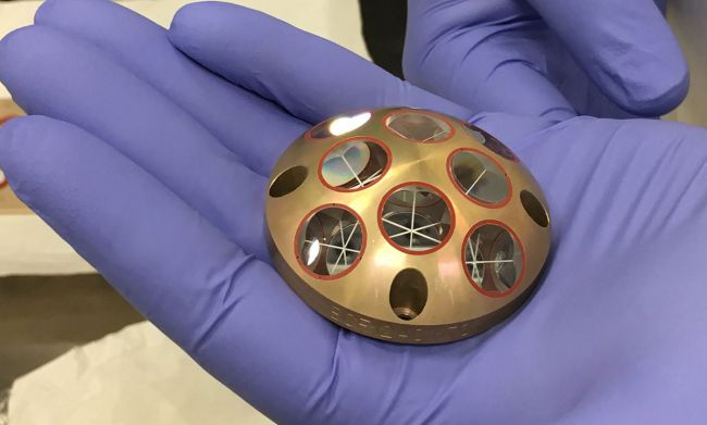
Chandrayaan-2 carries 13 Indian payloads — eight on the orbiter, three on the lander and two on the rover. In addition, the lander carries a passive Laser Retroreflector Array (LRA) provided by NASA.
Laser Retroreflector Array (LRA). Source: ISRO
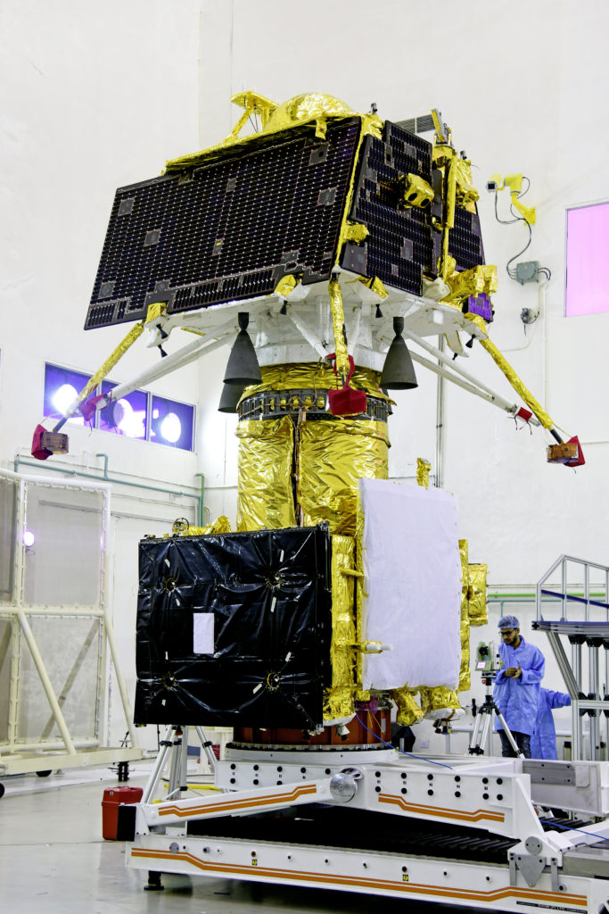
The OC and the LC are stacked together within the payload fairing of the launch vehicle and remain stacked until the LC separates in lunar orbit and starts its descent to the lunar surface.
Orbiter (bottom) & lander (top) in stacked configuration. Source: ISRO
The solar-powered orbiter is designed for a one-year mission to map lunar surface characteristics (chemical, mineralogical, topographical), probe the lunar surface for water ice, and map the lunar exosphere using the CHACE-2 mass spectrometer. The orbiter also will relay communication between Earth and Vikram lander.
The orbiter. Source: ISRO
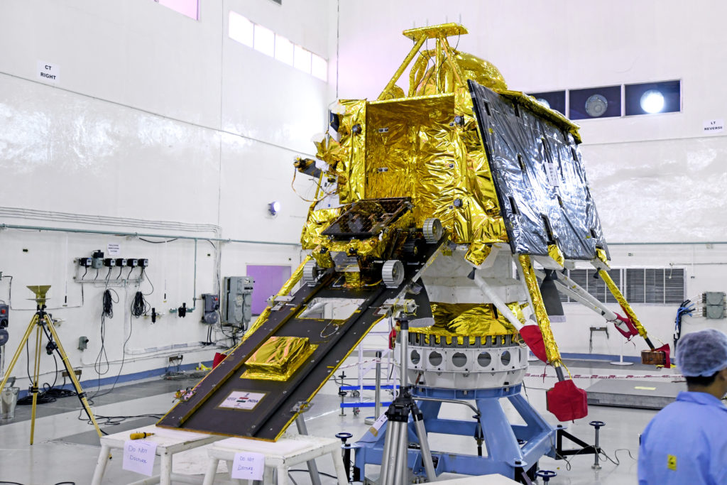
The solar-powered Vikram lander weighs 1,471 kg (3,243 lb). The scientific instruments on the lander will measure lunar seismicity, measure thermal properties of the lunar regolith in the polar region, and measure near-surface plasma density and its changes with time.
The Vikram lander with the Pragyan rover on the ramp.Source: ISRO
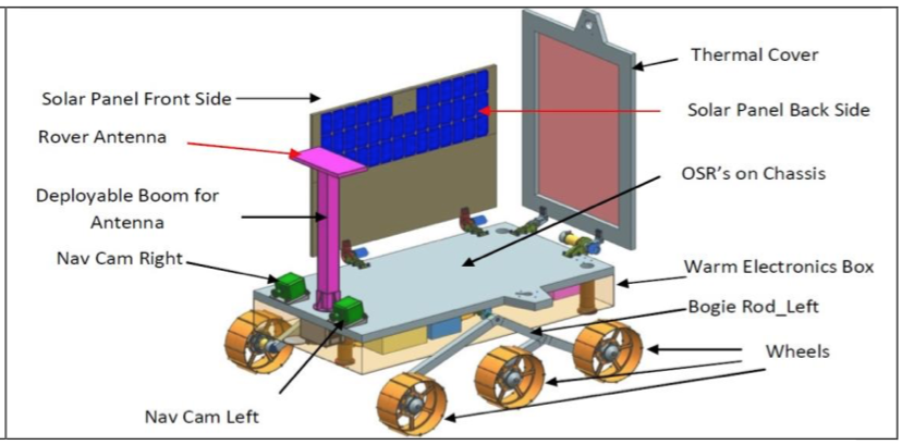
The 27 kg (59.5 lb) six-wheeled Pragyan rover, whose name means “wisdom” in Sanskrit, is solar-powered and capable of traveling up to 500 meters (1,640 feet) on the lunar surface. The rover can communicate only with the Vikram lander. It is designed for a 14-day mission on the lunar surface. It is equipped with cameras and two spectroscopes to study the elemental composition of lunar soil.
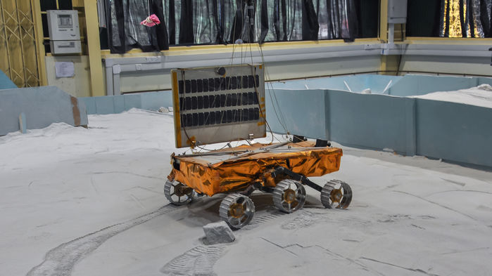
Rover during testing. Source: ISRORover details. Source: ISRO
You’ll find more information on the spacecraft in the 2018 article by V. Sundararajan, “Overview and Technical Architecture of India’s Chandrayaan-2 Mission to the Moon,” at the following link:
Best wishes to the Chandrayaan-2 mission team for a successful soft lunar landing and long-term lunar mapping mission.
Update 2 December 2019: Vikram lander crashed on the Moon
After a 48-day transit following launch, and an apparently nominal descent toward the lunar surface, communications with the Vikram lander were lost on 6 September 2019, when the spacecraft was at an altitude of about 2 km (1.2 miles), with just seconds remaining before the planned landing. Communications with the Chandrayaan orbiter continued after communications was lost with the Vikram lander. More details on India’s failed landing attempt are in the 25 November 2019 article on the Space.com website here: https://www.space.com/india-admits-moon-lander-crash.html


