On 15 Nov 1960, the FBM submarine USS George Washington (SSBN-598) embarked on the nation’s first Polaris nuclear deterrent patrol armed with 16 intermediate range Polaris A1 submarine launched ballistic missiles (SLBMs). This milestone occurred just 3 years 11 months after the Polaris FBM program was funded by Congress and authorized by the Secretary of Defense. The 1st deterrent patrol was completed 66 days later on 21 January 1961.
USS George Washington underway. Source: Navsource
The original US FBM submarine force consisted of 41 Polaris submarines, in five sub-classes (George Washington, Ethan Allen, Lafayette, James Madison and Benjamin Franklin), that were authorized between 1957 and l963. Through several rounds of modifications, most of these submarines were adapted to handle later versions of the Polaris SLBM (A2, A3 and A4) and some were modified to handle the Poseidon (C3) SLBM. Twelve of the James Madison- and Ben Franklin-class boats were modified the late 1970s and early 1980s to handle the long range Trident I C4 SLBMs.
A total of 1,245 Polaris deterrent patrols were made in a period of about 21 years, from the first Polaris A-1 deterrent patrol by USS George Washington in 1960, and ending with the last Polaris A-3 deterrent patrol by USS Robert E. Lee (SSBN-601), which started on 1 October 1981. By then, the remainder of the original Polaris SSBN fleet had transitioned to Poseidon (C3) and Trident I (C4) SLBMs.
The next generation of US ballistic missile submarines was the Ohio-class SSBN, 18 of which were ordered between 1974 and 1990 (one per fiscal year). The lead ship of this class, USS Ohio (SSBN 726), was commissioned in 1981 and deployed 6 September 1982 on its first strategic deterrent patrol, armed with the Trident I (C4) SLBM. Beginning with the 9th boat in class, USS Tennessee (SSBN-734), the remaining Ohio- class SSBNs were equipped originally to handle the larger Trident II (D5). Four of the early boats were upgraded to handle the Trident II (D5) missile. The earliest four, including the USS Ohio, were converted to cruise missile submarines to comply with strategic weapons treaty limits.
Evolution of the US submarine strategic nuclear deterrent fleet. Johns Hopkins APL Technical Digest, Volume 29, Number 4, 2011
The Federation of American Scientists (FAS) reported that the US Navy conducted 4,086 submarine strategic deterrent patrols between 1969 and 2017. At that time, the Navy was conducting strategic deterrent patrols at a steady rate of around 30 patrols per year. By the end of 2020, that total must be approaching 4,175 patrols.
Source: Hans Kristensen, FAS, 2018
In 2020, the US maintains a fleet of 14 Trident missile submarines armed with D5LE (life extension) SLBMs. By about 2031, the first of the new Columbia-class SSBN is expected to be ready to start its first deterrent patrol. Ohio-class SSBNs will be retired on a one-for-one bases when the new Columbia-class SSBNs are delivered to the fleet and ready to assume deterrent patrol duties.
The USS George was defueled and declared scrapped in September 1998. Owing to her place in history as the first US ballistic missile submarine and her successful completion of 55 deterrent patrols in both the Atlantic & Pacific Oceans, the George Washington’s sail was preserved and returned to New London, CT where it is now displayed outside of the gates of the US Submarine Force Library and Museum.
The USS George Washington’s sail on display outside the US Submarine Force Library and Museum in New London, CT. Source: Wikimapia
John Gibson & Stephen Yanek, “The Fleet Ballistic Missile Strategic Weapon System: APL’s Efforts for the U.S. Navy’s Strategic Deterrent System and the Relevance to Systems Engineering,” Johns Hopkins APL Technical Digest, Volume 29, Number 4, 2011: https://www.jhuapl.edu/Content/techdigest/pdf/V29-N04/29-04-Gibsonl.pdf
In the U.S., tritium for nuclear weapons was one of several products produced by the Atomic Energy Commission (AEC) and its successor, the Department of Energy (DOE), during the Cold War. The machines for tritium production were water-cooled, graphite-moderated production reactors in Hanford, Washington, and heavy water cooled and moderated production reactors at the Savannah River Plant (SRP, now Savannah River Site, SRS) in South Carolina. Lithium “targets,” containing enriched lithium-6 produced at the Y-12 Plant in Oak Ridge Tennessee, were irradiated in these reactors to produce tritium. Later, tritium was extracted from the targets, purified and packaged for use in nuclear weapons in separate facilities, initially at Hanford and Los Alamos and later at Savannah River.
Today, tritium for the U.S. nuclear weapons stockpile is produced in light water cooled and moderated commercial pressurized water reactors (PWRs) owned and operated by the Tennessee Valley Authority (TVA). Tritium is extracted from the targets, purified and packaged for use in nuclear weapons at the Savannah River Site (SRS).
The following three timelines provide details on tritium production activities in the Cold War nuclear weapons complex:
Under the Manhattan Project and through the Cold War, the U.S. developed and operated a dedicated nuclear weapons complex that performed all of the functions needed to transform raw materials into complete nuclear weapons. After the end of the Cold War (circa 1991), U.S. and Russian nuclear weapons stockpiles were greatly reduced. In the U.S., the nuclear weapons complex contracted and atrophied, with some functions being discontinued as the associated facilities were retired without replacement, while other functions continued at a reduced level, many in aging facilities.
In its current state, the U.S. nuclear weapons complex is struggling to deliver an adequate supply of tritium to meet the needs specified by the National Nuclear Security Administration (NNSA) for “stockpile stewardship and maintenance,” or in other words, for keeping the nuclear weapons in the current, smaller stockpile safe and operational. Key issues include:
There have been no dedicated tritium production reactors operating since 1988. Natural radioactive decay has been steadily reducing the existing inventory of tritium.
Commercial light water reactors (CLWRs) have been put into dual-use service since 2003 to produce tritium for NNSA while generating electric power that is sold commercially. The current tritium production rate needs to increase significantly to meet needs.
There has been a continuing decline in the national inventory of “unobligated” (i.e., free from peaceful use obligations) low-enriched uranium (LEU) and high-enriched uranium (HEU). This unobligated uranium can be used for military purposes, such as fueling the dual-use tritium production reactors.
There has been no “unobligated” U.S. uranium enrichment capability since 2013. The technology for a replacement enrichment facility has not yet been selected.
The U.S. domestic uranium production industry has declined to a small fraction of the capacity that existed from the mid-1950s to the mid-1980s. About 10% of uranium purchases in 2018 were from U.S. suppliers, and 90% came from other countries. NNSA’s new enrichment facility will need a domestic source of natural uranium.
There has been no operational lithium-6 production facility since the late 1980s.
There has been a continuing decline in the national inventory of enriched lithium-6, which is irradiated in “targets” to produce tritium.
Only one tritium extraction facility exists.
The U.S. nuclear weapons complex for tritium production is relatively fragile, with several milestone dates within the next decade that must be met in order to reach and sustain the desired tritium production capacity. There is little redundancy within this part of the nuclear weapons complex. Hence, tritium production is potentially vulnerable to the loss of a single key facility.
This complex story is organized in this post as follows.
Two key materials – Tritium and Lithium
Cold War tritium production
Hanford Project P-10 (later renamed P-10-X) for tritium production (1949 to 1954)
Hanford N-Reactor Coproduct Program for tritium production (1963 to 1967)
Savannah River Plant tritium production (1954 to 1988)
Synopsis of U.S. Cold War tritium production
The Interregnum of U.S Tritium Production (1988 to 2003)
New Production Reactor (NPR) Program
Accelerator Tritium Production (ATP)
Tritium recycling
The U.S. commercial light water reactor (CLWR) tritium production program (2003 to present)
Structure of the CLWR program
What is a TPBAR?
Operational use of TPBARs in TVA reactors
Where will the uranium fuel for the TVA reactors come from?
Tritium, or hydrogen-3, is naturally occurring in extremely small quantities (10-18 percent of naturally occurring hydrogen) or it can be artificially produced at great cost. The current tritium price is reported to be about $30,000 per gram, making it the most expensive substance by weight in the world today.
Tritium is a radioactive isotope of hydrogen with a half-life of 12.32 years. Tritium decays into helium-3 by means of negative beta decay, which also produces an electron (e–) and an electron antineutrino, as shown below.
Source: nuclear-power.net
Tritium is an important component of thermonuclear weapons. The tritium is stored in a small, sealed reservoir in each warhead.
With its relatively short half-life, the tritium content of the reservoir is depleted at a rate of 5.5% per year and must be replenished periodically. In 1999, DOE reported in DOE/EIS-0271 that none of the weapons in the U.S. nuclear arsenal would be capable of functioning as designed without tritium.
During the Cold War-era, the Atomic Energy Commission (AEC, and its successor in 1977, the Department of Energy, DOE) produced tritium for nuclear weapons in water-cooled, graphite-moderated production reactors in Hanford, Washington and in heavy water cooled and moderated production reactors at the Savannah River Plant (SRP, now Savannah River Site, SRS) in South Carolina. These reactors also produced plutonium, polonium and other nuclear materials. All of these production reactors were dedicated defense reactors except the dual-use Hanford-N reactor, which also could produce electricity for sale to the commercial power grid.
Tritium is produced by neutron absorption in a lithium-6 atom, which splits to form an atom of tritium (T) and an atom of helium-4. This process is shown below.
Natural lithium is composed of two stable isotopes; about 7.5% lithium-6 and 92.5% lithium-7. To improve tritium production, lithium-6 and lithium-7 are separated and the enriched lithium-6 is used to make “targets” that will be irradiated in nuclear reactors to produce tritium. The separated, enriched lithium-7 is a valuable material for other nuclear applications because of its very low neutron cross-section. Oak Ridge Materials Chemistry Division initiated work in 1949 to find a method to separate the lithium isotopes, with the primary goal of producing high purity lithium-7 for use in Aircraft Nuclear Propulsion (ANP) reactors.
Lithium-6 enrichment process development with a focus on tritium production began in 1950 at the Y-12 Plant in Oak Ridge, Tennessee. Three different enrichment processes would be developed with the goal of producing highly-enriched (30 to 95%) lithium-6: electric exchange (ELEX), organic exchange (OREX) and column exchange (COLEX). Pilot process lines (pilot plants) for all three processes were built and operated between 1951 and 1955.
Production-scale lithium-6 enrichment using the ELEX process was conducted at Y-12 from 1953 to 1956. The more efficient COLEX process operated at Y-12 from 1955 to 1963. By that time, a stockpile of enriched lithium-6 had been established at Oak Ridge, along with a stockpile of unprocessed natural lithium feed material.
The enriched lithium-6 material produced at Y-12 was shipped to manufacturing facilities at Hanford and Savannah River and incorporated into control rods and target elements that were inserted into a production reactor core and irradiated for a period of time.
After irradiation, these control rods and target elements were removed from the reactor and processed to recover the tritium that was produced. The recovered tritium was purified and then mixed with a specified amount of deuterium (hydrogen-2, 2H or D) before being loaded and sealed in reservoirs for nuclear weapons.
Tritium production at Hanford ended in 1967 and at Savannah River in 1988. The U.S. had no source of new tritium production for its nuclear weapons program between 1988 and 2003. During that period, tritium recycling from retired weapons was the primary source of tritium for the weapons remaining in the active stockpile. Finally, in 2003, the nation’s new replacement source of tritium for nuclear weapons started coming on line.
3. Cold War Tritium Production
3.1 Hanford Project P-10 (later renamed P-10-X) for tritium production (1949 to 1954)
The industrial process for producing plutonium for WW II nuclear weapons was conceived and built as part of the Manhattan Project. On 21 December 1942, the U.S. Army issued a contract to E. I. Du Pont de Nemours and Company (DuPont), stipulating that DuPont was in charge of designing, building and operating the future plutonium plant at a site still to be selected. The Hanford, Washington, site was selected in mid-January 1943.
Starting in 1949, the earliest work involving tritium production by irradiation of lithium targets in nuclear reactors was performed at Hanford under Project P-10 (later renamed P-10-X). By this time, DuPont had built and was operating four water-cooled, graphite-moderated production reactors at Hanford: B and D Reactors (1944), F Reactor (1945) and H Reactor (1949). Project P-10-X involved only the B and H Reactors, which were modified for tritium production.
Tritium was recovered from the targets in Building 108-B, which housed the first operational tritium extraction process line in the AEC’s nuclear weapons complex. The thermal extraction process employed started with melting the target material in a vacuum furnace and then collecting and purifying the tritium drawn off in the vacuum line. This tritium product was sent to Los Alamos for further processing and use.
Hanford site 100-B area. B Reactor is the tiered building near the center of the photo. The much smaller 108-B tritium extraction process line building is sitting alone on the right. Source: atomicarchive.com
Project P-10-X provided the initial U.S. tritium production capability from 1949 to 1954 and supplied the tritium for the first U.S. test of a thermonuclear device, Ivy Mike, in November 1952. Thereafter, most tritium production and all tritium extractions were accomplished at the Savannah River Plant.
DOE reported: “During its five years of operation, Project P-10-X extracted more than 11 million Curies (Ci) of tritium representing a delivered amount of product of about 1.2 kg.” For more details, see the report PNNL-15829, Appendix D: “Tritium Inventories Associated with Tritium Production,” which is available here:
3.2. Hanford N-Reactor Coproduct Program for tritium production (1963 to 1967)
This was a tritium production technology development program conducted in the mid-1960s. Its primary aim was not to produce tritium for the U.S. nuclear weapons program, but rather to develop technologies and materials that could be applied in tritium breeding blankets in fusion reactors. After an extensive review of candidate lithium-bearing target materials, the high melting point ceramic lithium aluminate (LiAlO2) was chosen.
Several fuel-target element designs were tested in-reactor, culminating in October 1965 with the selection of the “Mark II” design for use in the full-reactor demonstration. Targets were double-clad cylindrical elements with a lithium aluminate core. The first cladding layer was 8001 aluminum; the second (outer) cladding layer was Zircaloy-2.
Hanford N Coproduct Target Element. Source: BNWL-2097
During the N Reactor coproduct demonstration, four distinct production tests were run, the first two with small numbers of fuel and target columns being irradiated, and the last two runs with over 1,500 fuel and target columns containing about 17 tons LiAlO2. The last production test, PT-NR-87, recorded the highest N Reactor power level by operating at 4,800 MWt for 31 hours.
The irradiated target elements were shipped to SRP for tritium extraction using a thermal extraction process defined jointly by Pacific Northwest Laboratory (PNL, now Pacific Northwest National Laboratory, PNNL) and Savannah River Laboratories (SRL). The existing tritium extraction vacuum furnaces at SRP were used.
This completed the Hanford N Reactor Coproduct Program.
More details are available in PNNL report BNWL-2097, “Tritium Production from Ceramic Targets: A Summary of the Hanford Coproduct Program,” which is available at the following link:
This program provided important experience related to lithium aluminate ceramic targets for tritium production.
3.3. Savannah River Plant tritium production (1954 to 1988)
The Savannah River Plant (SRP) was designed in 1950 primarily for a military mission to produce tritium, and secondarily to produce plutonium and other special nuclear materials, including Pu-238. DuPont built five dedicated production reactors at the SRP and became operational between 1953 and 1955: the R reactor (prototype) and the later P, L, K and C reactors.
In 1955, the original maximum power of C Reactor was 378 MWt. With ongoing reactor and system improvements, C Reactor was operating at 2,575 MWt in 1960, and eventually was rated for a peak power of 2,915 MWt in 1967. The other SRP production reactors received similar reactor and system improvements. The increased reactor power levels greatly increased the tritium production capacity at SRP. You’ll find SRP reactor operating power history charts in Chapter 2 of “The Savannah River Site Dose Reconstruction Project -Phase II,” report at the following link:
Enriched lithium-6 product was sent from the Oak Ridge Y-12 Plant to SRP Building 320-M, where it was alloyed with aluminum, cast into billets, extruded to the proper diameter, cut to the required length, canned in aluminum and assembled into control rods or “driver” fuel elements.From 1953 to 1955, tritium was produced only in control rods. Lithium-aluminum alloy target rods (“producer rods”) were installed in the septifoil (7-chambered) aluminum control rods in combination with cadmium neutron poison rods to get the desired reactivity control characteristics.
Cross-section of a septifoil control rod. Source: The Savannah River Site at Fifty (1950 – 2000), Chapter 13
Starting in 1955, enriched uranium “driver” fuel cylinders and lithium target “slugs” were assembled in a quatrefoil (4-chambered) configuration, which provided much more target mass in the core for tritium production.
Cross-section of a quatrefoil driver fuel / target element. Source: The Savannah River Site at Fifty (1950 – 2000), Chapter 13
Enriched uranium drivers were extruded in Building 320-M until 1957, after which they were produced in the newly constructed Building 321-M. Production rate varied with the needs of the reactors, peaking in 1983, when the operations in Building 321-M went to 24 hours a day. Manufacturing ceased in 1989 after the last production reactors, K, L and P, were shut down.
K Reactor was operated briefly, and for the last time, in 1992 when it was connected to a new cooling tower that was built in anticipation of continued reactor operation. K Reactor was placed in cold-standby in 1993, but with no planned provision for restart as the nation’s last remaining source of new tritium production. In 1996, K Reactor was permanently shut down.
3.4. Synopsis of U.S. Cold War tritium production
The Federation of American Scientists (FAS) estimated that the total U.S. tritium production (uncorrected for radioactive decay) through 1984 was about 179 kg (about 396 pounds).
DOE reported a total of 10.6 kg (23.4 pounds) of tritium was produced at Hanford:
About 1.2 kg (2.7 pounds) was produced at the B and H Reactors during Project P-10-X.
The balance of Hanford production (9.4 kg, 20.7 pounds) is attributed to N Reactor operation during the Coproduct Program.
The majority of U.S. tritium production through 1984 occurred at the Savannah River Plant: about 168.4 kg (371.3 pounds).
4. The Interregnum of U.S Tritium Production (1988 – 2003)
DOE had shut down all of its Cold War-era production reactors. Tritium production at Hanford ended in 1967 and at Savannah River in 1988, leaving the U.S. temporarily with no source of new tritium for its nuclear weapons program. At the time, nobody thought that “temporary” meant 15 years (a period I call the “Interregnum”).
DOE’s search for new production capacity focused on four different reactor technologies and one particle accelerator technology. During the Interregnum, the primary source of tritium was from recycling tritium reservoirs from nuclear weapons that had been retired from the stockpile. This worked well at first, but tritium decays.
4.1 New Production Reactor (NPR) Program
From 1988 to 1992, DOE conducted the New Production Reactor (NPR) Program to evaluate four candidate technologies for a new generation of production reactors that were optimized for tritium production, but with the option to produce plutonium:
Heavy water cooled and moderated reactor (HWR)
High-temperature gas-cooled reactor (HTGR)
Light water cooled and moderated reactor (LWR)
Liquid metal reactor (LMR)
Three candidate NPR sites were considered:
Savannah River Site
Idaho National Engineering Laboratory (INEL, now INL)
Hanford Site
The NPR schedule goal was to have the new reactors start tritium production within 10 years after the start of conceptual design. Details on this program are available in DOE/NP-0007P, “New Production Reactors – Program Plan,” dated December 1990, which is available here: https://www.osti.gov/servlets/purl/6320732
The NPR program was cancelled in September 1992 (some say “deferred”) after DOE failed to select a preferred technology and failed to gain Congressional budgetary support for the program, at least in part due to the end of the Cold War.
DOE continued evaluating other options for tritium production, including commercial light water reactors (CLWRs) and accelerator tritium production (ATP).
4.2 Accelerator Tritium Production (ATP)
A candidate ATP design developed by Los Alamos National Laboratory (LANL) was based on a 1,700 MeV (million electron volt) linear accelerator that produced a 170 MW / 100 mA continuous proton beam. The ATP total electric power requirement was 486 MWe. The general arrangement of the ATP is shown in the following diagrams.
General arrangement of the ATP. Source: LANL
In this diagram, beam energy is indicated along the linear accelerator, increasing to the right and reaching a maximum of 1,700 MeV just before entering a magnetic switch that diverts the beam to the target/blanket or allows to beam to continue straight ahead to a tuning backstop.
Details of the Target / Blanket System. Source: LANL
The Target / Blanket System operates as follows:
The continuous proton beam is directed onto a tungsten target surrounded by a lead blanket, generating a huge flux of spallation neutrons.
Tubes filled with Helium-3 gas are located adjacent to the tungsten and within the lead blanket.
The spallation neutrons created by the energetic protons are moderated by the lead and cooling water and are absorbed by Helium-3 to create about 40 tritium atoms per incident proton.
The tritium is continuously removed from the Helium-3 gas in a nearby Tritium Separation Facility.
The unique feature of on-line, continuous tritium collection eliminates the time and processing required to extract tritium from the target elements used in production reactors.
ATP ultimately was rejected by DOE in December 1998 in favor of producing tritium in a commercial light water reactor (CLWR).
After the end of the Cold War, both the U.S. and Russia greatly reduced their respective stockpiles of nuclear weapons, as shown in the following chart.
Source: Wikipedia
The decommissioning of many nuclear weapons created an opportunity for the U.S. to temporarily maintain an adequate supply of tritium by recycling the tritium from the reservoirs no longer needed in warheads being retired from service. However, by 2020, after 32 years of exponential decay at a rate of 5.5% per year, the 1988 U.S. tritium inventory had decayed to only about 17% of the inventory in 1988, when the DOE stopped producing tritium. You can check my math using the following exponential decay formula:
y = a (1-b)x
where:
y = the fractional amount remaining after x periods
a = initial amount = 1
b = the decay rate per period (per year) = 0.055
x = number of periods (years) = 32
Recycling tritium from retired and aged reservoirs and precisely reloading reservoirs for installation in existing nuclear weapons are among the important functions performed today at DOE’s Savannah River Site (SRS). But, clearly, there is a point in time where simply recycling tritium reservoirs is no longer an adequate strategy for maintaining the current U.S. stockpile of nuclear weapons. A source of new tritium for military use was required.
5. The U.S. commercial light water reactor (CLWR) tritium production program (2003 to present)
In December 1998, Secretary of Energy Bill Richardson announced the decision to select commercial light water reactors (CLWRs) as the primary tritium supply technology, using government-owned Tennessee Valley Authority (TVA) reactors for irradiation services. A key commitment made by DOE was that the reactors would be required to use U.S.-origin low-enriched uranium (LEU) fuel. In their September 2018 report R45406, the Congressional Research Service noted: “Long-standing U.S. policy has sought to separate domestic nuclear power plants from the U.S. nuclear weapons program – this is not only an element of U.S. nuclear nonproliferation policy but also a result of foreign ‘peaceful-use obligations’ that constrain the use of foreign-origin nuclear materials.”
5.1 Structure of the CLWR program
The current U.S. CLWR tritium production capability was deployed in about 12 years, between 1995 and 2007, as shown in the following high-level program plan.
CLWR tritium production program plan. Source: adapted from NNSA 2001
Since early 2007, NNSA has been getting its new tritium supply for nuclear stockpile maintenance from tritium-producing burnable absorber rods (TPBARs) that have been irradiated in the slightly-modified core of TVA’s Watts Bar Unit 1 (WBN 1) nuclear power plant, which is a Westinghouse commercial pressurized water reactor (PWR) licensed by the U.S. Nuclear Regulatory Commission (NRC).
TVA’s Watts Bar nuclear power plant. Source: Oak Ridge Today, 13 Feb 2019
The NRC’s June 2005 “Backgrounder” entitled, “Tritium Production,” provides a good synopsis of the development and nuclear licensing work that led to the approval of TVA nuclear power plants Watts Bar Unit 1 and Sequoyah Units 1 and 2 for use as irradiation sources for tritium production for NNSA. You find the NRC Backgrounder here:
The CLWR tritium production cycle is shown in the following NNSA diagram. Not included in this diagram are the following:
Supply of U.S.-origin LEU for the fuel elements.
Production of fuel elements using this LEU
Management of irradiated fuel elements at the TVA reactor sites
The current U.S. tritium production cycle. Source: NNSA and Art Explosion via GAO-11-100
PNNL is the TPBAR design authority (agent) and is responsible for coordinating irradiation testing of TPBAR components in the Advanced Test Reactor (ATR) at the Idaho National Laboratory (INL). Production TPBAR components are manufactured by several contractors in accordance with specifications from PNNL, with WesDyne International responsible for assembling the complete TPBARs in Columbia, South Carolina. When needed, new TPBARs are shipped to TVA for installation in a designated reactor during a scheduled refueling outage and then irradiated for 18 months, until the next refueling outage. After being removed from the reactor, the irradiated TPBARs are allowed to cool at the TVA nuclear power plant for a period of time and then are shipped to the Savannah River Site.
SRS is the only facility in the nuclear security complex that has the capability to extract, recycle, purify, and reload tritium. Today, the Savannah River Tritium Enterprise (SRTE) is the collective term for the facilities, people, expertise, and activities at the SRS related to tritium production. SRTE is responsible for extracting new tritium from irradiated TPBARs at the Tritium Extraction Facility (TEF) that became operational in January 2007. They also are responsible for recycling tritium from reservoirs of existing warheads. The existing Tritium Loading Facility at SRS packages the tritium in sealed reservoirs for delivery to DoD. You’ll find the SRTE fact sheet at the following link:
Program participants and their respective roles are identified in the following diagram.
The current U.S. tritium production program participants. Source: NNSA 2001
5.2 What is a TPBAR?
The reactor core in a Westinghouse commercial four-loop PWR like Watts Bar Unit 1 approximates a right circular cylinder with an active core measuring about 14 feet (4.3 meters) tall and 11.1 feet (3.4 meters) in diameter. The reactor core has 193 fuel elements, each of which is comprised of a 17 x 17 square array of 264 small-diameter, fixed fuel rods and 25 small-diameter empty thimbles, 24 of which serve as guide thimbles for control rods and one is an instrumentation thimble.
Rod cluster control assemblies (RCCAs) are used to control the reactor by moving arrays of small-diameter neutron-absorbing control rods into or out of selected fuel elements in the reactor core. Watts Bar has 57 RCCAs, each comprised of 24 Ag-In-Cd (silver-indium-cadmium) neutron-absorbing rods that fit into the control rod guide thimbles in selected fuel elements. Each RCCA is controlled by a separate control rod drive mechanism. The geometries of a Westinghouse 17 x 17 fuel element and the RCCA are shown in the following diagrams.
Cross-sectional view of a single Westinghouse 17 x 17 fuel element showing the lattice positions assigned to fuel rods (red) andthe thimbles available for instrumentation and control rods (blue).Source: Syeilendra Pramuditya Isometric view of a Westinghouse 17 x 17 fuel element showing the fixed fuel rods (red) and a rod cluster control assembly (yellow) that can be inserted or withdrawn for reactivity control. Sources: (L) Framatom ANP report BAW-10237, May 2001; (R) Westinghouse via NuclearTourist
To produce tritium in a Westinghouse PWR core, lithium-6 targets, in the form of lithium aluminate (LiAlO2) ceramic pellets, are inserted into the core and irradiated. This is accomplished with the tritium-producing burnable absorber rods (TPBARs), each of which is a small-diameter rod (a “rodlet”) that externally looks quite similar to a single control rod in an RCCA. During one typical 18-month refueling cycle (actually, up to 550 equivalent full power days), the tritium production per rod is expected to be in a range from 0.15 to 1.2 grams. The ceramic lithium aluminate target is similar to the targets developed in the mid-1960s and used during the Hanford N-Reactor Coproduct Program for tritium production.
A TPBAR “feed batch” assembly generally resembles the shape of an RCCA, but with 12 or 24 TPBAR rodlets in place of the control rods. The feed batch assembly is a hanging structure supported by the top nozzle adapter plate of the fuel assembly and the TPBAR rodlets are hanging in the guide thimble tubes of the fuel assembly. The feed batch assembly does not move after it has been installed in the reactor core.
Since lithium-6 is a strong neutron absorber, the TPBAR functions in the reactor core in a manner similar to fixed burnable absorber rods, which use boron-10 as their neutron absorber. The reactivity worth of the TPBARs is slightly greater than the burnable absorber rods.
In 2001, Framatome ANP issued Report BAW-10237, “Implementation and Utilization of Tritium Producing Burnable Absorber Rods (TPBARS) in Sequoyah Units 1 and 2.” This report provides a good description of the modified core and TPBARs as they would be applied for tritium production at the Sequoyah nuclear plant. Watts Bar should be similar. The report is here:
The feed batch assembly and TPBAR rodlet configurations are shown in the following diagram.
TPBAR feed batch assembly (left); details of an individual TPBAR and target pellet (right). Source: NNSA 2001
TPBARs were designed for a low rate of tritium permeation from the target pellets, through the cladding and into the primary coolant water. Tritium permeation performance was expected to be less than 1.0 Curie/one TPBAR rod/year. With an assumed maximum of 2,304 TPBARs in the reactor core, the NRC initially licensed Watts Bar Unit 1 for a maximum annual tritium permeation of 2,304 Curies / year.
5.3. Operational use of TPBARs in TVA reactors
NRC issued WBN 1 License Amendment 40 in September 2002, approving the irradiation of up to 2,304 TPBARs per operating cycle.
For the first irradiation cycle (Cycle 6) starting in the autumn of 2003, TVA received NRC approval to operate with only 240 TPBARs because of issues related to Reactor Coolant System (RCS) boron concentration. Actual TPBAR performance during Cycle 6 demonstrated a significantly higher rate of tritium permeation than expected; reported to be about 4.0 Curies/one TPBAR/cycle.
TVA’s short-term response was to limit the number of TPBARs per core load to 240 in Cycles 7 and 8 to ensure compliance with its NRC license limits on tritium release. In their 30 January 2015 letter to TVA, NRC stated, “….the primary constraint on the number of TPBARs in the core is the TPBAR tritium release per year of 2,304 Curies per year.” This guidance gave TVA some flexibility on the actual number of TPBARs that could be irradiated per cycle. This NRC letter is available here: https://www.nrc.gov/docs/ML1503/ML15030A508.pdf
PNNL’s examinations of TPBARs revealed no design or production flaws. Nonetheless, PNNL developed design modifications intended to improve tritium permeation performance. These changes were implemented by the manufacturing contractors, resulting in the Mark 9.2 TPBAR, which was first used in 2008 in WBN 1 Cycle 9. PNNL also is conducting an ongoing irradiation testing programs in the Advanced Test Reactor (ATR) at INL, with the goal of finding a technical solution for the high permeation rate. You’ll find details on this program in a 2013 PNNL presentation at the following link: https://www.energy.gov/sites/prod/files/2015/08/f26/Senor%20-%20TMIST-3%20Irradiation%20Experiment.pdf
In October 2010, the General Accounting Office (GAO) reported: “no discernable improvement in TPBAR performance was made and tritium is still permeating from the TPBARs at higher-than-expected rates.” This GAO report is available here: https://www.gao.gov/products/GAO-11-100
In response to the high tritium permeation rate, the irradiation management strategy was revised based on an assumed permeation rate of 5.0 Curies per TPBAR per year (five times the original expected rate). Even at this higher permeation rate, WBN 1 can meet the NRC requirements in 10 CFR Part 20 and 10 CFR Part 50 Appendix I related to controlling radioactive materials in gaseous and liquid effluents produced during normal conditions, including expected occurrences.
The many NRC license amendments associated with WBN 1 tritium production are summarized below:
In License Amendment 40 (Sep 2002), the NRC originally approved WBN 1 to operate with up to 2,304 TPBARs.
Cycle 6: TVA limited the maximum number of TPBARs to be irradiated to 240 based on issues related to Reactor Coolant System (RCS) boron concentration. Approved by NRC in WBN 1 License Amendment 48 (Oct 2003).
Cycles 7 & 8: WBN 1 continued operating with 240 TPBARs.
Cycle 9: First use of TPBARs Mark 9.2 supported TVAs request to increase the maximum number of TPBARs to 400. Approved by NRC in WBN 1 License Amendment 67 (Jan 2008)
Cycle 10: TVA reduced the number of TPBARs irradiated to 240 after discovering that the Mark 9.2 TPBAR design changes deployed in Cycle 9 did not significantly reduce tritium permeation.
Cycles 11 to 14: NRC License Amendment 77 9May 2009) allowed a maximum of 704 TPBARs at WBN 1. TVA chose to irradiate only 544 TPBARs in Cycles 11 and 12, increasing to 704 TPBARs for Cycles 13 & 14.
Cycles 15 & beyond: NRC License Amendment 107 (Aug 2016) allows a maximum of 1,792 TPBARs at WBN 1.
The actual number of TPBARs and the average tritium production per TPBAR during WBN 1 Cycles 6 to 14 are summarized in the 2017 PNNL presentation, “Tritium Production Assurance,” and are reproduced in the following table.
Tritium production, WBN 1 Cycles 6 to 14 (Cycle 14, completed in 2011, is an estimate). Source: PNNL, Tritium Production Assurance, 11 May 2017
The current tritium production plan continues irradiation in WBN 1 and starts irradiation in Watts Bar Unit 2 (WBN 2) in Cycle 4, which will start after the spring 2022 refueling. Tritium is assumed to be delivered six months after the end of each cycle.
WBN 1 and WBN 2 TPBAR loading plans. Source: “Tritium Production Assurance”, report of the PNNL Tritium Focus Group, Richland, WA, May 11, 2017
As of early 2020, TVA and DOE are not delivering the quantity of tritium expected by NNSA. In July 2019, DOE and NNSA delivered their “Fiscal Year 2020 – Stockpile Stewardship and Management Plan” to Congress. In this plan, the top-level goal was to “recapitalize existing infrastructure to implement a plan to produce no less than 80 ppy (plutonium pits per year) by 2030.” To meet this goal, NNSA set a target for increasing tritium production to 2,800 grams per two 18-month reactor cycles of production at TVA by 2027. This means two TVA reactors will be producing tritium, and each will have a target of about 1,400 grams per cycle. This will be quite a challenge for TVA and DOE.
5.4 Where will the uranium fuel for the TVA reactors come from?
The tritium-producing TVA reactors are committed to using unobligated LEU fuel. That means that the uranium is not encumbered by international obligations that restrict its use for peaceful purposes only. Unobligated uranium has a very special pedigree. The uranium originated from U.S. mines, was processed in U.S. facilities, and was enriched in an unobligated U.S. enrichment facility.
Today, that front-end of the U.S. nuclear fuel cycle has withered against international competition, as shown in the following chart from the Energy Information Administration (EIA).
Since the U.S. has not had an unobligated uranium enrichment facility since 2013, when the Paducah enrichment plant was closed by the Obama administration, there currently is no source of new unobligated LEU for the tritium-producing TVA reactors.
The impending shortage of unobligated enriched uranium eventually could affect tritium production, Navy nuclear reactor operation and other users. This matter has been addressed by the GAO in their 2018 report GAO-18-126, “NNSA Should Clarify Long-Term Uranium Enrichment Mission Needs and Improve Technology Cost Estimates,” which is available here:
The solution could be a mixture of measures, some of which are discussed briefly below.
Downblend unobligated HEU to buy time
Currently, the LEU for the TVA reactors is supplied from the U.S. inventory of unobligated LEU, which is supplemented by downblending unobligated HEU. In September 2018, NNSA awarded Nuclear Fuel Services (NFS) a $505 million contract to downblend 20.2 metric tons of HEU to produce LEU, which can serve as a short-term source of fuel for the tritium-producing TVA reactors. This contract runs from 2019 to 2025. Beyond 2025, additional HEU downblending may be needed to sustain tritium production until a longer-term solution is in place.
Build a new unobligated uranium enrichment facility and re-build the associated domestic uranium mining, milling and conversion infrastructure
NNSA is in the process of selecting the preferred technology for a new unobligated enrichment plant. There are two competing enrichment technologies: the Centrus AC-100 large advanced gas centrifuge and the Oak Ridge National Laboratory small advanced gas centrifuge, both of which are designed to enrich gaseous uranium hexafluoride (UF6).
NNSA failed to meet its goal of making the selection by the end of 2019. Regardless of the choice, it will take more than a decade to deploy such a facility. Perhaps a mid-2030’s date would be a possible target for initial operation of a new DOE uranium enrichment facility.
In the meantime, the atrophied / shutdown US uranium mining, milling and conversion industries need to be rebuilt to once again establish a reliable, domestic source of feed material for DOE’s uranium enrichment operations. This will be a daunting task given the current sad state of the US uranium production industry.
In May 2020, the US Energy Information Administration (EIA) released its 2019 Domestic Uranium Production Report. Mining uranium ore or in-situ leaching from underground uranium ore bodies, followed by the production of uranium (U3O8) concentrate (”yellowcake”), are the first steps at the front-end of the nuclear fuel cycle. The following EIA summary graphic shows the decline of US uranium production, which has been especially dramatic since 2013.
US uranium (U3O8) concentrate production and shipments, 1996–2019. Source: EIA
A key point reported by the EIA was that total US production of uranium concentrate from all domestic sources in 2019 was only 170,000 pounds (77,111 kg) of U3O8, 89% less than in 2018, from six facilities. In the graphic, you can see that US annual production in 1996 was about 35 times greater, approximately 6,000,000 pounds (2,721,554 kg). This EIA report is available at the following link: https://www.eia.gov/uranium/production/annual/
Conversion of U3O8 to UF6 is the next step in the front-end of the nuclear fuel cycle. Honeywell’s Metropolis Works was built in 1958 to produce UF6 for US government programs, including the nuclear weapons complex. Therefore, the Metropolis Works should be an unobligated conversion plant and, as such, is an important facility in the nuclear fuel cycle for the US tritium production reactors operated by TVA. In 2020, the Metropolis Works is the only US facility that can receives uranium ore concentrate and convert it to UF6.
In 1968, Metropolis Works began selling UF6 on the commercial nuclear market. However, since 2017, operations at the Metropolis Works have been curtailed due to weak market conditions for its conversion services and Honeywell has maintained the facility in a “ready-idle” status. In March 2020, the NRC granted the Metropolis Works a 40-year license renewal, permitting operations until March 24, 2060. When demand resumes, the Metropolis Works should be ready to resume operation.
Recognizing the US national interest in having a viable industrial base for the front-end of the nuclear fuel cycle, President Trump established a Nuclear Fuel Working Group in July 2019. On 13 April, 2020, the DOE released the “Strategy to Restore American Nuclear Energy Leadership,” which, among other things, includes recommendations to strengthen the US uranium mining and conversion industries and restore the viability of the entire front-end of the nuclear fuel cycle. You’ll find this DOE announcement and a link to the full report to the President here: https://www.energy.gov/articles/secretary-brouillette-announces-nuclear-fuel-working-groups-strategy-restore-american
Reprocess enriched DOE and naval fuel spent fuel
A large inventory of aluminum clad irradiated fuel exists at SRS, with a smaller quantity at INL. The only operating chemical separations (reprocessing) facility in the U.S. is the H-Canyon facility at SRS, which can only process aluminum clad fuel. However, the cost to operate H-Canyon to process the aluminum-clad fuel would be high.
There is a large inventory of irradiated, zirconium-clad naval fuel at INL. This fuel started life with a uranium enrichment level of 93% or higher. In 2017, INL completed a study examining the feasibility of processing zirconium-clad spent fuel through a new process called ZIRCEX. This process could enable reprocessing the spent naval fuel stored at INL as well as other types of zirconium-clad fuel.
In 2018, the U.S. Senate approved $15 million in funding for a pilot program at the INL to “recycle” irradiated (used) naval nuclear fuel and produce high-assay, low-enriched uranium (HALEU) fuel with an enrichment between 5% to 20% for use in “advanced reactors.” It seems that a logical extension would be to also produce LEU fuel to a specification that could be used in the TVA reactors.
In 2018, Idaho Senator Mike Crapo made the following report to the Senate: “HEU repurposing, from materials like spent naval fuel, can be done using hybrid processes that use advanced dry head-end technologies followed by material recovery, which creates the fuel for our new advanced reactors. Repurposing this spent fuel has the potential of reducing waste that would otherwise be disposed of at taxpayer expense, and approximately 1 metric ton of HEU can create 4 useable tons (of HALEU) for our new reactors.”
Perhaps there is a future for closing the back-end of the naval fuel cycle and recovering some of the investment that went into producing the very highly enriched uranium used in naval reactors. Because of the high burnup in long-life naval reactors, the resulting HALEU or LEU will have different uranium isotopic proportions than LEU produced in the front-end of the fuel cycle. This may introduce issues that would have to be reviewed and approved by the NRC before such LEU fuel could be used in the TVA reactors.
Other options
More information on options for obtaining enriched uranium without acquiring a new uranium enrichment facility is provided in Appendix II of GAO-18-126.
5.5 Where will the enriched lithium-6 target material come from?
A reliable source of lithium-6 target material is needed to produce the TPBARs for TVA’s tritium-producing reactors.
The U.S. has not had an operational lithium-6 production facility since 1963 when the last COLEX (column exchange) enrichment line was shutdown. COLEX was one of three lithium enrichment technologies employed at the Y-12 Plant in Oak Ridge, TN between 1950 and 1963. The others technologies were ELEX (electrical exchange) and OREX (organic exchange). All of these processes used large quantities of mercury. At the time lithium-6 enrichment operations ceased at Y-12, a stockpile of enriched lithium-6 and lithium-7 had been established along with a stockpile of unprocessed natural lithium feed material.
There has been a continuing decline in the national inventory of enriched lithium-6. To extend the existing supply, NNSA has instituted a program to recover and recycle lithium components from nuclear weapons that are being retired from the stockpile.
In May 2017, Y-12 lithium activities were adversely affected by the poor physical condition (and partial roof collapse) of the WW II-vintage Building 9204-2 (Beta 2).
Shortly thereafter, NNSA announced the approval of plans for a new Lithium Production Facility at Y-12 to replace Building 9204-2. The NNSA’s Fiscal Year 2020 – Stockpile Stewardship and Management Plan set an operational date of 2030 for the new facility.
5.6 Where is the tritium recovered?
Tritium is extracted from the irradiated TPBARs, purified and loaded into reservoirs at the Savannah River Site (SRS). These functions are performed by “Savannah River Tritium Enterprise” (SRTE), which is the collective term for the tritium facilities, people, expertise, and activities at the SRS.
The first load of irradiated TPBARs were consolidated at Watts Bar and delivered to SRS in August 2005 for storage pending completion of the new Tritium Extraction Facility (TEF). The TEF became fully operational and started extracting tritium from TPBARs in January 2007. The tritium extracted at TEF is transferred to the H Area New Manufacturing (HANM) Facility for purification. In February 2007, the first newly-produced tritium was delivered to the SRS Tritium Loading Facility for loading into reservoirs for nuclear weapons.
From 2007 until 2017, the TEF conducted only a single extraction each year because of the limited quantities of TPBARs being irradiated in the TVA reactors. During this period, the TEF sat idle for nine months each year between extraction cycles.
In 2017, for the first time, the TEF performed three extractions in a single year using the original vacuum furnace. Each extraction typically involved 300 TPBARs.
In November 2019, SRTE’s capacity for processing TPBARs and recovering tritium was increased by the addition of a second vacuum furnace.
6. Conclusions
In their “Fiscal Year 2020 – Stockpile Stewardship and Management Plan,” the NNSA’s top-level goal is to “recapitalize existing infrastructure to implement a plan to produce no less than 80 ppy (plutonium pits per year) by 2030.” This goal will drive tritium production demand, which in turn will drive demands for unobligated LEU to fuel TVA’s tritium-producing reactors and enriched lithium-6 for TPBARs.
The U.S. nuclear fuel cycle for the production of tritium currently is incomplete. It is able to produce tritium by using temporary measures that are not sustainable:
Downblending HEU to produce LEU
Recycling tritium as the primary means for meeting current demand
Recycling lithium components
The next 15 years will be quite a challenge for the NNSA, DOE and TVA as they work to reestablish a complete, modern nuclear fuel cycle for tritium production. There are several milestones on the critical path that would adversely impact tritium production if they are not met on schedule:
Higher tritium production goals for the TVA reactors: deliver 2,800 grams of tritium per two 18-month reactor cycles of production in TVA reactors by 2027
New Lithium Facility at Y-12 operational by 2030
New uranium enrichment facility operational, perhaps by the mid-2030s
There is a general lack of redundancy in the existing and planned future nuclear fuel cycle for tritium production. This makes tritium production vulnerable to a major outage at a single non-redundant facility.
“National Nuclear Security Administration Needs to Ensure Continued Availability of Tritium for the Weapons Stockpile,” Report GAO-11-100, General Accounting Office, October 2010: https://www.gao.gov/assets/320/311092.pdf
Sean Johnson, “Making the invisible engineer visible: DuPont and the recognition of nuclear expertise,” Technology and Culture, Volume 52, Number 3, July 2011, pp. 548-573: https://muse.jhu.edu/article/447781/pdf
For more information on Cold War-era Hanford tritium production:
Johnson AB, Jr., TJ Kabele, and WE Gurwell, “Tritium Production from Ceramic Targets: A Summary of the Hanford Coproduct Program,” BNWL-2097, Pacific Northwest National Laboratory, 1976: https://www.osti.gov/servlets/purl/7125831
Johnson AB, Jr., TJ Kabele, and WE Gurwell, “Tritium Production from Ceramic Targets: A Summary of the Hanford Coproduct Program,” BNWL-2097, Pacific Northwest National Laboratory, 1976: https://www.osti.gov/servlets/purl/7125831
1. Overview of US military optical reconnaissance satellite programs
The National Reconnaissance Office (NRO) is responsible for developing and operating space reconnaissance systems and conducting intelligence-related activities for US national security. NRO developed several generations of classified Keyhole (KH) military optical reconnaissance satellites that have been the primary sources of Earth imagery for the US Department of Defense (DoD) and intelligence agencies. NRO’s website is here:
NRO’s early generations of Keyhole satellites were placed in low Earth orbits, acquired the desired photographic images on film during relatively short-duration missions, and then returned the film to Earth in small reentry capsules for airborne recovery. After recovery, the film was processed and analyzed. The first US military optical reconnaissance satellite program, code named CORONA, pioneered the development and refinement of the technologies, equipment and systems needed to deploy an operational orbital optical reconnaissance capability. The first successful CORONA film recovery occurred on 19 August 1960.
Specially modified US Air Force C-119J aircraft recovers a CORONA film canister in flight. Source: US Air Force
First reconnaissance picture taken in orbit and successfully recovered on Earth; taken on 18 August 1960 by a CORONA KH-1 satellite dubbed Discoverer 14. Image shows the Mys Shmidta airfield in the Chukotka region of the Russian Arctic, with a resolution of about 40 feet (12.2 meters). Source: Wikipedia
Keyhole satellites are identified by a code word and a “KH” designator, as summarized in the following table.
In 1976, NRO deployed its first electronic imaging optical reconnaissance satellite known as KENNEN KH-11 (renamed CRYSTAL in 1982), which eventually replaced the KH-9, and brought an end to reconnaissance satellite missions requiring film return. The KH-11 flies long-duration missions and returns its digital images in near real time to ground stations for processing and analysis. The KH-11, or an advanced version sometimes referred to as the KH-12, is operational today.
US film-return reconnaissance satellites from KH-1 to KH-9 shown to scale with the KH-11 electronic imaging reconaissance satellite. Credit: Giuseppe De Chiara and The Space Review.
Geospatial intelligence, or GEOINT, is the exploitation and analysis of imagery and geospatial information to describe, assess and visually depict physical features and geographically referenced activities on the Earth. GEOINT consists of imagery, imagery intelligence and geospatial information. Satellite imagery from Keyhole reconnaissance satellites is an important information source for national security-related GEOINT activities.
The National Geospatial-Intelligence Agency (NGA), which was formed in 2003, has the primary mission of collecting, analyzing, and distributing GEOINT in support of national security. NGA’s predecessor agencies, with comparable missions, were:
National Imagery and Mapping Agency (NIMA), 1996 – 2003
National Photographic Interpretation Center (NPIC), a joint project of the Central Intelligence Agency (CIA) and DoD, 1961 – 1996
2. The advent of the US civilian Earth observation programs
Collecting Earth imagery from orbit became an operational US military capability more than a decade before the start of the joint National Aeronautics & Space Administration (NASA) / US Geological Survey (USGS) civilian Landsat Earth observation program. The first Landsat satellite was launched on 23 July 1972 with two electronic observing systems, both of which had a spatial resolution of about 80 meters (262 feet).
Since 1972, Landsat satellites have continuously acquired low-to-moderate resolution digital images of the Earth’s land surface, providing long-term data about the status of natural resources and the environment. Resolution of the current generation multi-spectral scanner on Landsat 9 is 30 meters (98 feet) in visible light bands.
3. Declassification of certain military reconnaissance satellite imagery
All military reconnaissance satellite imagery was highly classified until 1995, when some imagery from early defense reconnaissance satellite programs was declassified. The USGS explains:
“The images were originally used for reconnaissance and to produce maps for U.S. intelligence agencies. In 1992, an Environmental Task Force evaluated the application of early satellite data for environmental studies. Since the CORONA, ARGON, and LANYARD data were no longer critical to national security and could be of historical value for global change research, the images were declassified by Executive Order 12951 in 1995”
Additional sets of military reconnaissance satellite imagery were declassified in 2002 and 2011 based on extensions of Executive Order 12951.
The declassified imagery is held by the following two organizations:
The original film is held by the National Archives and Records Administration (NARA).
Duplicate film held in the USGS Earth Resources Observation and Science (EROS) Center archive is used to produce digital copies of the imagery for distribution to users.
The declassified military satellite imagery available in the EROS archive is summarized below:
USGS EROS Archive – Declassified Satellite Imagery – 1 (1960 to 1972)
This set of photos, declassified in 1995, consists of more than 860,000 images of the Earth’s surface from the CORONA, ARGON, and LANYARD satellite systems.
CORONA image resolution improved from 40 feet (12.2 meters) for the KH-1 to about 6 feet (1.8 meters) for the KH-4B.
KH-5 ARGON image resolution was about 460 feet (140 meters).
KH-6 LANYARD image resolution was about 6 feet (1.8 meters).
USGS EROS Archive – Declassified Satellite Imagery – 2 (1963 to 1980)
This set of photos, declassified in 2002, consists of photographs from the KH-7 GAMBIT surveillance system and KH-9 HEXAGON mapping program.
KH-7 image resolution is 2 to 4 feet (0.6 to 1.2 meters). About 18,000 black-and-white images and 230 color images are available.
The KH-9 mapping camera was designed to support mapping requirements and exact positioning of geographical points. Not all KH-9 satellite missions included a mapping camera. Image resolution is 20 to 30 feet (6 to 9 meters); significantly better than the 98 feet (30 meter) resolution of LANDSAT imagery. About 29,000 mapping images are available.
USGS EROS Archive – Declassified Satellite Imagery – 3 (1971 to 1984)
This set of photos, declassified in 2011, consists of more photographs from the KH-9 HEXAGON mapping program. Image resolution is 20 to 30 feet (6 to 9 meters).
4. Example applications of declassified military reconnaissance satellite imagery
The declassified military reconnaissance satellite imagery provides views of the Earth starting in the early 1960s, more than a decade before civilian Earth observation satellites became operational. The military reconnaissance satellite imagery, except from ARGON KH-5, is higher resolution than is available today from Landsat civilian earth observation satellites. The declassified imagery is an important supplement to other Earth imagery sources. Several examples applications of the declassified imagery are described below.
4.1 Assessing Aral Sea depletion
USGS reports: “The Aral Sea once covered about 68,000 square kilometers, a little bigger than the U.S. state of West Virginia. It was the 4th largest lake in the world. It is now only about 10% of the size it was in 1960…..In the 1990s, a dam was built to prevent North Aral water from flowing into the South Aral. It was rebuilt in 2005 and named the Kok-Aral Dam…..The North Aral has stabilized but the South Aral has continued to shrink and become saltier. Up until the 1960s, Aral Sea salinity was around 10 grams per liter, less than one-third the salinity of the ocean. The salinity level now exceeds 100 grams per liter in the South Aral, which is about three times saltier than the ocean.”
On the USGS website, the “Earthshots: Satellite Images of Environmental Change” webpages show the visible changes at many locations on Earth over a 50+ year time period. The table of contents to the Earthshots webpages is shown below and is at the following link: http:// https://earthshots.usgs.gov/earthshots/
USGS Earthshots Table of Contents
For the Aral Sea region, the Earthshots photo sequences start with ARGON KH-5 photos taken in 1964. Below are three screenshots of the USGS Earthshots pages showing the KH-5 images for the whole the Aral Sea, the North Aral Sea region and the South Aral Sea region. You can explore the Aral Sea Earthshots photo sequences at the following link: https://earthshots.usgs.gov/earthshots/node/91#ad-image-0-0
4.2 Assessing Antarctic ice shelf condition
In a 7 June 2016 article entitled, ”Spy satellites reveal early start to Antarctic ice shelf collapse,” Thomas Sumner reported:
“Analyzing declassified images from spy satellites, researchers discovered that the downhill flow of ice on Antarctica’s Larsen B ice shelf was already accelerating as early as the 1960s and ’70s. By the late 1980s, the average ice velocity at the front of the shelf was around 20 percent faster than in the preceding decades,….”
Satellite images taken by the ARGON KH-5 satellite have revealed how the accelerated movement that triggered the collapse of the Larsen B ice shelf on the east side of the Antarctic Peninsula began in the 1960s. The declassified images taken by the satellite on 29 August 1963 and 1 September 1963 are pictured right. Source: Daily Mail, 10 June 2016
4.3 Assessing Himalayan glacier condition
In a 19 June 2019 paper “Acceleration of ice loss across the Himalayas over the past 40 years,” the authors, reported on the use of HEXAGON KH-9 mapping camera imagery to improve their understanding of trends affecting the Himalayan glaciers from 1975 to 2016:
“Himalayan glaciers supply meltwater to densely populated catchments in South Asia, and regional observations of glacier change over multiple decades are needed to understand climate drivers and assess resulting impacts on glacier-fed rivers. Here, we quantify changes in ice thickness during the intervals 1975–2000 and 2000–2016 across the Himalayas, using a set of digital elevation models derived from cold war–era spy satellite film and modern stereo satellite imagery.”
“The majority of the KH-9 images here were acquired within a 3-year interval (1973–1976), and we processed a total of 42 images to provide sufficient spatial coverage.”
“We observe consistent ice loss along the entire 2000-km transect for both intervals and find a doubling of the average loss rate during 2000–2016.”
“Our compilation includes glaciers comprising approximately 34% of the total glacierized area in the region, which represents roughly 55% of the total ice volume based on recent ice thickness estimates.”
3-D image of the Himalayas derived from HEXAGON KH-9 satellite mapping photographs taken on December 20, 1975.Source: J. M. Maurer/LDEO
4.4 Discovering archaeological sites
A. CORONA Atlas Project
The Center for Advanced Spatial Technologies, a University of Arkansas / U.S. Geological Survey collaboration, has undertaken the CORONA Atlas Project using military reconnaissance satellite imagery to create the “CORONA Atlas & Referencing System”. The current Atlas focuses on the Middle East and a small area of Peru, and is derived from 1,024 CORONA images taken on 50 missions. The Atlas contains 833 archaeological sites.
“In regions like the Middle East, CORONA imagery is particularly important for archaeology because urban development, agricultural intensification, and reservoir construction over the past several decades have obscured or destroyed countless archaeological sites and other ancient features such as roads and canals. These sites are often clearly visible on CORONA imagery, enabling researchers to map sites that have been lost and to discover many that have never before been documented. However, the unique imaging geometry of the CORONA satellite cameras, which produced long, narrow film strips, makes correcting spatial distortions in the images very challenging and has therefore limited their use by researchers.”
Screenshot of the CORONA Atlas showing regions in the Middle East with data available.
CAST reports that they have “developed methods for efficient
orthorectification of CORONA imagery and now provides free public access to our imagery database for non-commercial use. Images can be viewed online and full resolution images can be downloaded in NITF format.”
In October 2023, a team from Dartmouth College published a paper that described their recent discovery of 396 Roman-era forts using declassified CORONA and HEXAGON spy satellite imagery of regions of Syria, Iraq and nearby “fertile crescent” territories of the eastern Mediterranean. The study area is shown in the following map. A previous aerial survey of the area in 1934 had identified 116 other forts in the same region.
Dartmouth study area. Source: J. Casana, et al. (26 October 2023)
The authors noted, “Perhaps the most significant realization from our work concerns the spatial distribution of the forts across the landscape, as this has major implications for our understanding of their intended purpose as well as for the administration of the eastern Roman frontier more generally.”
Comparison of the distribution of forts documented in the 1934 aerial survey (top)and forts found recently on declassified satellite imagery (bottom).Source: Figure 9, J. Casana, et al. (26 October 2023)
Examples of the new forts identified by the Dartmouth team in satellite imagery are shown in the following figures.
CORONA images showing three major sites: (A) Sura (NASA1401); (B) Resafa (NASA1398); and (C) Ain Sinu (CRN999).Source: Figure 3, J. Casana, et al. (26 October 2023)
Castellum at Tell Brak site in multiple images: (A) CORONA (1102, 17 December 1967); (B) CORONA (1105, 4 November 1968); (C) HEXAGON (1204, 17 November 1974); and (D) modern satellite imagery. Source: Figure 4, J. Casana, et al. (26 October 2023)
The teams paper concludes: “Finally, the discovery of such a large number of previously undocumented ancient forts in this well-studied region of the Near East is a testament to the power of remote-sensing technologies as transformative tools in contemporary archaeological research.”
4.5 Conducting commercial geospatial analytics over a broader period of time
The firm Orbital Insight, founded in 2013, is an example of commercial firms that are mining geospatial data and developing valuable information products for a wide range of customers. Orbital Insight reports:
“Orbital Insight turns millions of images into a big-picture understanding of Earth. Not only does this create unprecedented transparency, but it also empowers business and policy decision makers with new insights and unbiased knowledge of socio-economic trends. As the number of Earth-observing devices grows and their data output expands, Orbital Insight’s geospatial analytics platform finds observational truth in an interconnected world. We map out and quantify the world’s complexities so that organizations can make more informed decisions.”
“By applying artificial intelligence to satellite, UAV, and other geospatial data sources, we seek to discover and quantify societal and economic trends on Earth that are indistinguishable to the human eye. Combining this information with terrestrial data, such as mobile and location-based data, unlocks new sources of intelligence.”
5. Additional reading related to US optical reconnaissance satellites
You’ll find more information on the NRO’s film-return, optical reconnaissance satellites (KH-1 to KH-9) at the following links:
Robert Perry, “A History of Satellite Reconnaissance,” Volumes I to V, National Reconnaissance Office (NRO), various dates 1973 – 1974; released under FOIA and available for download on the NASA Spaceflight.com website, here: https://forum.nasaspaceflight.com/index.php?topic=20232.0
The best current supercomputers are “petascale” machines. This term refers to supercomputers capable of performing at least 1.0 petaflops [PFLOPS; 1015 floating-point operations per second (FLOPS)], and also refers to data storage systems capable of storing at least 1.0 petabyte (PB; 1015 bytes) of data.
In my 13 November 2018 post, I reported the latest TOP500 ranking of the world’s fastest supercomputers. The new leaders were two US supercomputers: Summit and Sierra. A year later, in November 2019, they remained at the top of the TOP500 ranking.
Summit: The #1 ranked IBM Summit is installed at the Department of Energy’s (DOE) Oak Ridge National Laboratory (ORNL) in Tennessee. It has a LINPACK Benchmark Rmax (maximal achieved performance) rating of 148.6 PFLOPS (1.486 x 10¹⁷ FLOPS) and an Rpeak (theoretical peak performance) rating of 200.8 PFLOPS. Summit’s peak electric power demand is 10.01 MW (megawatts).
Sierra:The #2 ranked IBM Sierra is installed at the DOE’s Lawrence Livermore National Laboratory (LLNL) in California. It has an Rmax rating of 94.64 PFLOPS (0.9464 x 10¹⁷ FLOPS) and an Rpeak rating of 125.7 PFLOPS. Sierra’s peak electric power demand is 7.44 MW.
The next update of the TOP500 ranking will be in June 2020. Check out their website here to see if the rankings change: http:// https://www.top500.org
New exascale machines are only a year or two away
The next big step up in supercomputing power will be the arrival of “exascale” machines, which refers to supercomputers capable of performing at least 1.0 exaflops (EFLOPS; 1018 FLOPS), and also refers to data storage systems capable of storing at least 1.0 exabyte (EB, 1018 bytes) of data. As you might suspect, there is intense international completion to be the first nation to operate an exascale supercomputer. The main players are the US, China and Japan.
In the US, DOE awarded contracts to build three new exascale supercomputers:
Aurora, announced in March 2019
Frontier, announced in May 2019
El Capitan, announced in March 2020
In this post, we’ll take a look at these three new supercomputers, each of which will be about ten times faster than the existing TOP500 leaders, Summit and Sierra.
Aurora supercomputer for ANL
The Aurora supercomputer is being built at Argonne National Laboratory (ANL) by the team of Intel (prime contractor) and Cray (subcontractor), under a contract valued at more than $500 million.
Aurora supercomputer concept drawing. Source: DOE / Argonne National Laboratory
The computer architecture is based on the Cray “Shasta” system and Intel’s Xeon Scalable processor, Xe compute architecture, Optane Datacenter Persistent Memory, and One API software. Those Cray and Intel technologies will be integrated into more than 200 Shasta cabinets, all connected by Cray’s Slingshot interconnect and associated software stack.
Aurora is expected to come online by the end of 2021 and likely will be the first exascale supercomputer in the US. It is being designed for sustained performance of one exaflops. An Argonne spokesman stated, “This platform is designed to tackle the largest AI (artificial intelligence) training and inference problems that we know about.”
The Frontier supercomputer is being built by at ORNL by the team of Cray (prime contractor) and Advanced Micro Devices, Inc. (AMD, subcontractor), under a contract valued at about $600 million.
Frontier supercomputer concept drawing. Source: DOE / Oak Ridge National Laboratory
The computer architecture is based on the Cray “Shasta” system and will consist of more than 100 Cray Shasta cabinets with high density “compute blades” that support a 4:1 GPU to CPU ratio using AMD EPYC processors (CPUs) and Radeon Instinct GPU accelerators purpose-built for the needs of exascale computing. Cray and AMD are co-designing and developing enhanced GPU programming tools.
Frontier is expected to come online in 2022 after Aurora, but is expected to be more powerful, with a rating of 1.5 exaflops. Frontier will find applications in deep learning, machine learning and data analytics for applications ranging from manufacturing to human health.
The El Capitan supercomputer, announced in March 2020, will be built at LLNL by the team of Hewlett Packard Enterprise (HPE) and AMD under a $600 million contract. El Capitan is funded by the DOE’s National Nuclear Security Administration (NNSA) under their Advanced Simulation and Computing (ASC) program. The primary users will be the three NNSA laboratories: LLNL, Sandia National Laboratories and Los Alamos National Laboratory. El Capitan will be used to perform complex predictive modeling and simulation to support NNSA’s nuclear weapons life extension programs (LEPs), which address aging weapons management, stockpile modernization and other matters.
El Capitan supercomputer concept drawing. Source: Hewlett Packard Enterprise
El Capitan’s peak performance is expected to exceed 2 exaflops, making it about twice as fast as Aurora and about 30% faster than Frontier.
LLNL describes the El Capitan hardware as follows: “El Capitan will be powered by next-generation AMD EPYC processors, code-named ‘Genoa’ and featuring the ‘Zen 4’ processor core, next-generation AMD Radeon Instinct GPUs based on a new compute-optimized architecture for workloads including HPC and AI, and the AMD Radeon Open Compute platform (ROCm) heterogeneous computing software.”
Hewlett Packard Enterprise acquires Cray in May 2019
On 17 May 2019, Hewlett Packard Enterprise (HPE) announced that it has acquired Cray, Inc. for about $1.3 billion. The following charts from the November 2018 TOP500 report gives some interesting insight into HPE’s rationale for acquiring Cray. In the Vendor’s System Share chart, both HPE and Cray have a 9 – 9.6% share of the market based on the number of installed TOP500 systems. In the Vendor’s Performance Share chart, the aggregate installed performance of Cray systems far exceeds the aggregate performance of a similar number of lower-end HPE systems (25.5% vs. 7.3%). The Cray product line fits above the existing HPE product line, and the acquisition of Cray should enable HPE to compete directly with IBM in the supercomputer market. HPE reported that it sees a growing market for exascale computing. The primary US customers are government laboratories.
The March 2020 award of NNSA’s El Capitan supercomputer to the HPE and AMD team seems to indicate that HPE made a good decision in their 2019 acquisition of Cray.
TOP500 ranking of supercomputer vendors, Nov 2018 Source: https://www.top500.org
Meanwhile in China:
On 19 May 2019, the South China Morning Post reported that China is making a multi-billion dollar investment to re-take the lead in supercomputer power. In the near-term (possibly in 2019), the newest Shuguang supercomputers are expected to operate about 50% faster than the US Summit supercomputer. This should put the new Chinese super computers in the Rmax = 210 – 250 PFLOPS range.
In addition, China is expected to have its own exascale supercomputer operating in 2020, a year ahead of the first US exascale machine, with most, if not all, of the hardware and software being developed in China. This computer will be installed at the Center of the Chinese Academy of Sciences (CAS) in Beijing.
Why, zettascale, of course. These will be supercomputers performing at least 1.0 zettaflops (ZFLOPS; 1021 FLOPS), while consuming about 100 megawatts (MW) of electrical power.
Peter Lobner, updated 28 Jun 2019, 14 Dec 2019 & 12 May 2020
JASON and the Naval Research Advisory Committee (NRAC) are both established, independent advisory groups that have long histories of providing important scientific and technical advice to the U.S. government, primarily to Department of Defense (DoD) clients. The Pentagon cancelled the JASON and NRAC contracts in early 2019. Immediately, efforts were undertaken on several fronts to attempt to restore funding. The efforts on behalf of JASON were successful, but NRAC was not so fortunate.
Following is an overview of these two advisory groups and an update on their current status.
1. JASON
JASON is an independent advisory panel of elite scientists that was created in 1960 to address a wide range of scientific and technical issues, primarily for the U.S. military. Originally, the JASON panel had about 20 members, known informally as Jasons, increasing to about 40 members by the 1970s. JASON maintains its independence by requiring that new members be selected by its existing members rather than by external sponsors.
JASON is a very controversial organization with a very low public profile. For a good introduction to JASON, I recommend Ann Finkbeiner’s 2006 book, “The Jasons: The Secret History of Science’s Postwar Elite,” which is available from Amazon and other booksellers. You can watch an hour-long video created by Microsoft Research with Ann Finkbeiner providing an excellent narrative overview (no Powerpoint slides) on JASON here:
Ann Finkbeiner notes: “Working in secrecy to solve highly classified problems for the Department of Defense, CIA, and NSA is an elite group of scientific advisors who provide the government with analyses on defense and arms control and they call themselves JASON. Named for the hero in Jason and the Argonauts, the group grew out of the Manhattan Project and counts as its members scientists such as Freeman Dyson and Murray Gell-Mann. Of the roughly one hundred Jasons over time, 43 have been elected to the National Academy of Sciences, eight have won MacArthur awards, one a Field’s Medal, and 11 have won Nobel Prizes. Its members have gathered every summer since 1960, working in absolute secrecy and with unparalleled freedom. The Jasons’ work poses vital questions: what role should the government play in scientific research? At what point is the inventor accountable for the hazards of the invention?”
You’ll find a list of JASON research topics compiled on Wikipedia here:
Most of the resulting JASON reports are classified. You’ll find a list of unclassified JASON reports (and links) on the Federation of American Scientists (FAS) website at the following link: https://fas.org/irp/agency/dod/jason/
Since the late 1970s, the JASONs have been assigned tasks and been funded via Indefinite Delivery / Indefinite Quantity (IDIQ) contracts managed by MITRE Corporation. The Office of the Secretary of Defense (OSD) issued MITRE’s most recent five-year IDIQ contract for managing JASON tasking and funding. Task Orders are issued under the main IDIQ contract and the actual work is performed according to the individual task orders. The IDIQ contract structure broadly allows government agencies to commission a JASON study and fund it via a new task order. MITRE’s IDIQ contract expired on 31 March 2019. A follow-on IDIQ contract was in the works, but OSD cancelled that solicitation on short notice on 28 March 2019.
On 10 April 2019, the article, “Pentagon Cancels Contract for JASON Advisory Panel,” written by Steven Aftergood, was posted on the FAS website at the following link: https://fas.org/blogs/secrecy/2019/04/pentagon-jason/
Aftergood speculated that, “The Pentagon move to cancel the JASON contract appears to be part of a larger trend by federal agencies to limit independent scientific and technical advice.”
Additional resources related to JASON
See the following documents for more background information on JASON.
Joel Shurkin, “True Genius: The Life and Work of Richard Garwin, the Most Influential Scientist You’ve Never Heard of,” Prometheus Books, ISBN-13: 978-1633882232, 21 February 2017
Joël van der Reijden, “The JASON Group: National Security Science,” Institute for the Study of Globalization and Covert Politics (ISGP), originally written 20 August 2005, version 3.5 posted 12 December 2014; https://isgp-studies.com/jason-group-national-security-science
Lyncean link
At meeting #65 of the Lyncean Group in August 2011, the subject of our presentation was “Experience with the JASONs.” See more at the following link: https://lynceans.org/talk-65-82411/
2. The Naval Research Advisory Committee (NRAC)
NRAC was established by Congressional legislation in 1946 and provided science and technology advice to the Navy for the past 73 years. NRAC is the Navy counterpart to the Army Science Board and the Air Force Scientific Advisory Board. Background information on NRAC is available on the Office of naval Research (ONR) website at the following link: https://www.onr.navy.mil/About-ONR/History/nrac
On 5 April 2019, Steve Aftergood reported that, “This week the U.S. Navy abruptly terminated its own scientific advisory group, depriving the service of a source of internal critique and evaluation. Now it’s gone. The decision to disestablish the Committee was announced in a March 29 Federal Register notice.” The cancellation of the NRAC contract may be part of the apparent trend by federal agencies to limit independent scientific and technical advice. You can read this report on the FAS website here: https://fas.org/blogs/secrecy/2019/04/nrac-terminated/
3. Update 28 June 2019: NNSA issues new contract for JASON
In April 2019, the Department of Energy’s National Nuclear Security Administration (NNSA) issued a notice of intent (NOI) for a sole-source contract to provide funding for JASON through at least January 2020. You’ll find this NOI here: https://fas.org/irp/agency/dod/jason/nnsa-jason-noi.pdf
This article provides a good overview of the history of JASON and offers the following view on future funding for the group.
“What happens when Jason’s contract with NNSA expires in 2020 is unclear. One possibility is yet another home within DOD: This month, the U.S. House of Representatives added a line to DOD’s preliminary budget directing the Office of the Under Secretary of Defense for Acquisition and Sustainment to pick up Jason’s contract.”
4. Update 14 December 2019: DoD contract for JASON is in the 2020 DoD Budget
On 11 December 2019, Steve Aftergood reported that Congress, via the National Defense Authorization Act for 2020, has directed the Department of Defense to reach an “arrangement with the JASON scientific advisory group to conduct national security studies and analyses.” Aftergood identified the following specific JASON studies:
Performed in 2019: Nuclear weapon pit aging (NNSA), bio threats (DOE), and fundamental research security (NSF)
Planned for 2020: Assessments of electronic warfare programs, and options for replacing the W78 warhead currently carried by the Minuteman III intercontinental ballistic missile force
5. Update 12 May 2020: JASON COVID-19 pro bono study
On 11 May 2020, Jeffrey Mervis, writing for the Science.mag website, reported that JASON was engaged in a pro bono study, led by Massachusetts Institute of Technology (MIT) physicist Peter Fisher, of how to reopen university laboratories safely in the midst of the corona virus pandemic. The results of this JASON study are expected in June 2020 and should be a useful resource for university officials and government agencies that are now drafting their own policies on reopening.
On 19 January 1942, US President Franklin D. Roosevelt approved the production of an atomic bomb. At that time, most of the technology for producing an atomic bomb still needed to be developed and the US had very little infrastructure in place to support that work.
The Manhattan Engineer District (MED, aka the “Manhattan Project”) was responsible for the research, design, construction and operation of the early US nuclear weapons complex and for delivering atomic bombs to the US Army during World War II (WW II) and in the immediate post-war period. The Manhattan Project existed for just five years. In 1943, 75 years ago, the Manhattan Project transitioned from planning to construction and initial operation of the first US nuclear weapons complex facilities. Here’s a very brief timeline for the Manhattan Project.
13 August 1942: The Manhattan Engineer District was formally created under the leadership of U.S. Army Colonel Leslie R. Groves.
2 December 1942: A team led by Enrico Fermi achieved the world’s first self-sustaining nuclear chain reaction in a graphite-moderated, natural uranium fueled reactor known simply as Chicago Pile-1 (CP-1).
1943 – 1946: The Manhattan Project managed the construction and operation of the entire US nuclear weapons complex.
16 July 1945: The first nuclear device was successfully tested at the Trinity site near Alamogordo, NM, less than three years after the Manhattan Project was created.
6 & 9 August 1945: Atomic bombs were employed by the US against Japan, contributing to ending World War II.
1 January 1947: The newly formed, civilian-led Atomic Energy Commission (AEC) took over management and operation of all research and production facilities from the Manhattan Engineer District.
25 August 1947: The Manhattan Engineer District was abolished.
The WW II nuclear weapons complex was the foundation for the early US post-war nuclear weapons infrastructure that evolved significantly over time to support the US mutually-assured destruction strategy during the Cold War with the Soviet Union. Today, the US nuclear weapons complex continues to evolve as needed to perform its critical role in maintaining the US nuclear deterrent capability.
2. A Closer Look at the Manhattan Project Timeline
You’ll find a comprehensive, interactive timeline of the Manhattan Project on the Department of Energy’s (DOE) OSTI website at the following link:
The Atomic Heritage Foundation is dedicated to “supporting the Manhattan Project National Historical Park and capturing the memories of the people who harnessed the energy of the atom.” Their homepage is here:
The Manhattan Project National Historical Park was authorized by Congress in December 2014 and subsequently was approved by the President to commemorate the Manhattan Project. The Manhattan Project National Historical Park is an extended “park” that currently is comprised of three distinct DOE sites that each had different missions during WW II:
Los Alamos, New Mexico: Nuclear device design, test and production
Oak Ridge, Tennessee: Enriched uranium production
Hanford, Washington: Plutonium production
On 10 November 2015, a memorandum of agreement between DOE and the National Park Service (NPS) established the park and the respective roles of DOE and NPS in managing the park and protecting and presenting certain historic structures to the public.
You’ll find the Manhattan Project National Historical Park website here:
Following is a brief overview of the three sites that currently comprise the Manhattan Project National Historical Park.
3.1. Los Alamos, New Mexico
Los Alamos Laboratory was established 75 years ago, in early 1943, as MED Site Y, under the direction of J. Robert Oppenheimer. This was the Manhattan Project’s nuclear weapons laboratory, which was created to consolidate in one secure, remote location most of the research, design, development and production work associated producing usable nuclear weapons to the US Army during WW II.
Los Alamos Laboratory main gate circa 1944. Source: Los Alamos National Laboratory
The first wave of scientists began arriving at Los Alamos Laboratory in April 1943. Just 27 months later, on 16 July 1945, the world’s first nuclear device was detonated 200 miles south of Los Alamos at the Trinity Site near Alamogordo, NM. This was the plutonium-fueled, implosion-type device code named “Gadget.”
During WW II, the Los Alamos Laboratory produced three atomic bombs:
One uranium-fueled, gun-type atomic bomb code named “Little Boy” was produced. This was the atomic bomb dropped on Hiroshima, Japan on 6 August 1945, making it the first nuclear weapon used in warfare. This atomic bomb design was not tested before it was used operationally.
Two plutonium-fueled, implosion-type atomic bombs code named “Fat Man” were produced. These bombs were very similar to Gadget. One of the Fat Man bombs was dropped on Nagasaki, Japan on 9 August 1945. The second Fat Man bomb could have been used during WW II, but it was not needed after Japan announced its surrender on 15 August 1945.
The highly-enriched uranium for the Little Boy bomb was produced by the enrichment plants at Oak Ridge. The plutonium for Gadget and the two Fat Man bombs was produced by the production reactors at Hanford.
Three historic sites are on Los Alamos National Laboratory property and currently are not open to the public:
Gun Site Facilities: three bunkered buildings (TA-8-1, TA-8-2, and TA-8-3), and a portable guard shack (TA-8-172).
V-Site Facilities: TA-16-516 and TA-16-517 V-Site Assembly Building
Pajarito Site: TA-18-1 Slotin Building, TA-8-2 Battleship Control Building, and the TA-18-29 Pond Cabin.
You’ll find information on the Manhattan Project National Historical Park sites at Los Alamos here:
Land acquisition was approved in 1942 for planned uranium “atomic production plants” in the Tennessee Valley. The selected site officially became the Clinton Engineer Works (CEW) in January 1943 and was given the MED code name Site X. This is where MED and its contractors managed the deployment during WW II of the following three different uranium enrichment technologies in three separate, large-scale industrial process facilities:
Liquid thermal diffusion process, based on work by Philip Abelson at Naval Research Laboratory and the Philadelphia Naval Yard. This process was implemented at S-50, which produced uranium enriched to < 2 at. % U-235.
Gaseous diffusion process, based on work by Harold Urey at Columbia University. This process was implemented at K-25, which produced uranium enriched to about 23 at. % U-235 during WW II.
Electromagnetic separation process, based on Ernest Lawrence’s invention of the cyclotron at the University of California Berkeley in the early 1930s. This process was implemented at Y-12 where the final output was weapons-grade uranium.
The Little Boy atomic bomb used 92.6 pounds (42 kg) of highly enriched uranium produced at Oak Ridge with contributions from all three of these processes.
The nearby township was named Oak Ridge in 1943, but the nuclear site itself was not officially renamed Oak Ridge until 1947.
The three Manhattan Project National Historical Park sites at Oak Ridge are:
X-10 Graphite Reactor National Historic Landmark
K-25 complex
Y-12 complex: Buildings 9731 and 9204-3
The S-50 Thermal Diffusion Plant was dismantled in the late 1940s. This site is not part of the Manhattan Project National Historical Park.
Following is a brief overview of X-10, K-25 and Y-12 historical sites. There’s much more information on the Manhattan Project National Historical Park sites at Oak Ridge here:
X-10 was the world’s second nuclear reactor (after the Chicago Pile, CP-1) and the first reactor designed and built for continuous operation. It was intended to produce the first significant quantities of plutonium, which were used by scientists at Los Alamos to characterize plutonium and develop the design of a plutonium-fueled atomic bomb.
X-10 was a large graphite-moderated, natural uranium fueled reactor that originally had an continuous design power rating of 1.0 MWt, which later was raised to 3.5 MWt. Originally, it was intended to be a prototype for the much larger plutonium production reactors being planned for Hanford. The selection of air cooling for X-10 enabled this reactor to be deployed more rapidly, but limited its value as a prototype for the future water-cooled plutonium production reactors.
The X-10 reactor core was comprised of graphite blocks arranged into a cube measuring 24 feet (7.3 meters) on each side. The core was surrounded by several feet of high-density concrete and other material to provide radiation shielding. The core and shielding were penetrated by 1,248 horizontal channels arranged in 36 rows. Each channel served to position up to 54 fuel slugs in the core and provide passages for forced air cooling of the core. Each fuel slug was an aluminum clad, metallic natural uranium cylinder measuring 4 inches (10.16 cm) long x 1.1 inches (2.79 cm) in diameter. New fuel slugs were added manually at the front face (the loading face) of the reactor and irradiated slugs were pushed out through the back face of the reactor, dropping into a cooling water pool. The reactor was controlled by a set of vertical control rods.
The basic geometry of the X-10 reactor is shown below.
X-10 Graphite Reactor general arrangement. Source: Department of Energy / Oak Ridge via https://en.wikipedia.org/Workers load fuel slugs into the X-10 Graphite Reactor circa 1952. Source: US Army / Manhattan Engineer District – Ed Westcott / American Museum of Science and Energy / https://en.wikipedia.org/
Site construction work started 75 years ago, on 27 April 1943. Initial criticality occurred less than seven months later, on 4 November 1943.
Plutonium was recovered from irradiated fuel slugs in a pilot-scale chemical separation line at Oak Ridge using the bismuth phosphate process. In April 1944, the first sample (grams) of reactor-bred plutonium from X-10 was delivered to Los Alamos. Analysis of this sample led Los Alamos scientists to eliminate one candidate plutonium bomb design (the “Thin Man” gun-type device) and focus their attention on the Fat Man implosion-type device. X-10 operated as a plutonium production reactor until January 1945, when it was turned over to research activities. X-10 was permanently shutdown on 4 November 1963, and was designated a National Historic Landmark on 15 October 1966.
K-25 Gaseous Diffusion Plant
Preliminary site work for the K-25 gaseous diffusion plant began 75 years ago, in May 1943, with work on the main building starting in October 1943. The six-stage pilot plant was ready for operation on 17 April 1944.
K-25 site circa 1944. Source: http://k-25virtualmuseum.org/timeline/index.html
The K-25 gaseous diffusion plant feed material was uranium hexafluoride gas (UF6) from natural uranium and slightly enriched uranium from both the S-50 liquid thermal diffusion plant and the first (Alpha) stage of the Y-12 electromagnetic separation plant. During WW II, the K-25 plant was capable of producing uranium enriched up to about 23 at. % U-235. This product became feed material for the second (Beta) stage of the Y-12 electromagnetic separation process, which continued the enrichment process and produced weapons-grade U-235.
As experience with the gaseous diffusion process improved and additional cascades were added, K-25 became capable of delivering highly-enriched uranium after WW II.
You can take a virtual tour of K-25, including its decommissioning and cleanup, here:
Construction on the second Oak Ridge gaseous diffusion plant, K-27, began on 3 April 1945. This plant became operational after WW II. By 1955, the K-25 complex had grown to include gaseous diffusion buildings K-25, K-27, K-29, K-31 and K-33 that comprised a multi-building, enriched uranium production chain collectively known as the Oak Ridge Gaseous Diffusion Plant (ORGDP). Operation of the ORGDP continued until 1985.
Additional post-war gaseous diffusion plants based on the technology developed at Oak Ridge were built and operated in Paducah, KY (1952 – 2013) and Portsmouth, OH (1954 – 2001).
Y-12 Electromagnetic Separation Plant
In 1941, Earnest Lawrence modified the 37-inch (94 cm) cyclotron in his laboratory at the University of California Berkeley to demonstrate the feasibility of electromagnetic separation of uranium isotopes using the same principle as a mass spectrograph.
The initial industrial-scale design agreed in 1942 was called an Alpha (α) calutron, which was designed to enrich natural uranium (@ 0.711 at.% U-235) to >10 at.% U-235. The later Beta (β) calutron was designed to further enrich the output of the Alpha calutrons, as well as the outputs from the K-25 and S-50 processes, and produce weapons-grade uranium at >88 at.% U-235.
The calutrons required large magnet coils to establish the strong electromagnetic field needed to separate the uranium isotopes U-235 and U-238. The shape of the magnet coils for both the Alfa and Beta calutrons resembled a racetrack, with many individual calutron modules (aka “tanks”) arranged side-by-side around the racetrack. At Y-12, there were nine Alpha calutron “tracks” (5 x Alpha-1 and 4 x Alpha-2 tracks), each with 96 calutron modules (tanks), for a total of 864 Alpha calutrons. In addition, there were eight Beta calutron tracks, each with 36 calutron modules, for a total of 288 beta calutrons, only 216 of which ever operated.
Due to wartime shortages of copper, the Manhattan Project arranged a loan from the Treasury Department of about 300 million Troy ounces (10,286 US tons) of silver for use in manufacturing the calutron magnet coils. A general arrangement of a Beta calutron module (tank) is shown in the following diagram, which also shows the isotope flight paths from the uranium tetrachloride (UCl4) ion source to the ion receivers. Separated uranium was recovered by burning the graphite ion receivers and extracting the metallic uranium from the ash.
General arrangement of a Beta calutron module (tank). Source: Oak Ridge drawing 42951, via Yergey & Yergey, 1997An Alpha calutron “racetrack” comprised of 96 individual calutron modules (tanks). Source: Department of Energy, Oak Ridge via https://commons.wikimedia.org/
Construction of Buildings 9731 and 9204-3 at the Y-12 complex began 75 years ago, in February 1943. By February 1944, initial operation of the Alpha calutrons had produced only 0.44 pounds (0.2 kg) of U-235 @ 12 at.%. By August 1945, the Y-12 Beta calutrons had produced the 92.6 pounds (42 kg) of weapons-grade uranium needed for the Little Boy atomic bomb.
After WW II, the silver was recovered from the calutron magnet coils and returned to the Treasury Department.
3.3. Hanford, Washington
On January 16, 1943, General Leslie Groves officially endorsed Hanford as the proposed plutonium production site, which was given the MED code name Site W. The plan was to construct three large graphite-moderated, water-cooled plutonium production reactors, designated B, D, and F, in along the Columbia River. The Hanford site also would include a facility for manufacturing the new uranium fuel slugs for the reactors as well as chemical separation plants and associated facilities to recover and process plutonium from the irradiated uranium slugs.
After WW II, six more plutonium production reactors were built at Hanford along with additional plutonium and nuclear waste processing and storage facilities.
The Manhattan Project National Historical Park sites at Hanford are:
B Reactor, which has been a National Historic Landmark since 19 August 2008
The previous Hanford High School in the former Town of Hanford and Hanford Construction Camp Historic District
Bruggemann’s Agricultural Warehouse Complex
White Bluffs Bank and Hanford Irrigation District Pump House
A brief overview of the B Reactor and the other Hanford production reactors is provided below. There’s more information on the Manhattan Project National Historical Park sites at Hanford here:
The Manhattan Project National Historical Park does not include the Hanford chemical separation plants and associated plutonium facilities in the 200 Area, the uranium fuel production plant in the 300 Area, or the other eight plutonium production reactors that were built in the 100 Area. Information on all Hanford facilities, including their current cleanup status, is available on the Hanford website here:
The B Reactor at the Hanford Site was the world’s first full-scale reactor and the first of three plutonium production reactor of the same design that became operational at Hanford during WW II. B Reactor and the similar D and F Reactors were significantly larger graphite-moderated reactor than the X-10 Graphite Reactor at Oak Ridge. The rectangular reactor core measured 36 feet (11 m) wide x 36 feet (11 m) tall x 28 feet (8.53 m) deep, surrounded by radiation shielding. These reactors were fueled by aluminum clad, metallic natural fuel slugs measuring 8 inches (20.3 cm) long x 1.5 inches (3.8 cm) in diameter. As with the X-10 Graphite Reactor, new fuel slugs were inserted into process tubes (fuel channels) at the front face of the reactor. The irradiated fuel slugs were pushed out of the fuel channels at the back face of the reactor, falling into a water pool to allow the slugs to cool before further processing for plutonium recovery.
Reactor cooling was provided by the once-through flow of filtered and processed fresh water drawn from the Columbia River. The heated water was discharged from the reactor into large retention basins that allowed some cooling time before the water was returned to the Columbia River.
Hanford production reactor general arrangement (Typical of B, D & F Reactor). Source: DOE/RL-97-1047, Department of Energy (DOE)Hanford production reactor core general arrangement (Typical of B, D, F, H, DR and C). Source: DOEThe front face (loading face) of B Reactor. Source: DOE
Construction of B Reactor began 75 years ago, in October 1943, and fuel loading started 11 months later, on September 13, 1944. Initial criticality occurred on 26 September 1944, followed shortly by operation at the initial design power of 250 MWt.
B Reactor was the first reactor to experience the effects of xenon poisoning due to the accumulation of Xenon (Xe-135) in the uranium fuel. Xe-135 is a decay product of the relatively short-lived (6.7 hour half-life) fission product iodine I-135. With its very high neutron cross-section, Xe-135 absorbed sufficient neutrons to significantly, and unexpectedly, reduce B Reactor power. Fortunately, DuPont had added more process tubes (a total of 2004) than called for in the original design of B Reactor. After the xenon poisoning problem was understood, additional fuel was loaded, providing the core with enough excess reactivity to override the neutron poisoning effects of Xe-135.
On 3 February 1945, the first batch of B Reactor plutonium was delivered to Los Alamos, just 10 months after the first small plutonium sample from the X-10 Graphite Reactor had been delivered.
B Reactor plutonium production complex at Hanford, in its heyday. Source: DOEB Reactor at Hanford today. Source: DOE
Regular plutonium deliveries from the Hanford production reactors provided the plutonium needed for the first ever nuclear device (the Gadget) tested at the Trinity site near Alamogordo, NM on 16 July 1945, as well as for the Fat Man atomic bomb dropped on Nagasaki, Japan on 9 August 1945 and an unused second Fat Man atomic bomb. These three devices each contained about 13.7 pounds (6.2 kilograms) of weapons-grade plutonium produced in the Hanford production reactors.
From March 1946 to June 1948, B Reactor was shut down for maintenance and modifications. In March 1949, B Reactor began the first tritium production campaign, irradiating targets containing lithium and producing tritium for hydrogen bombs.
By 1963, B Reactor was permitted to operate at a maximum power level of 2,090 MWt. B Reactor continued operation until 29 January 1968, when it was ordered shut down by the Atomic Energy Commission. Because of its historical significance, B Reactor was given special status that allows it to be open for public tours as part of the Manhattan Project National Historical Park.
The Other WW II Production Reactors at the Hanford Site: D & F
During WW II, three plutonium reactors of the same design were operational at Hanford: B, D and F. All had an initial design power rating of 250 MWt and by 1963 all were permitted to operate at a maximum power level of 2,090 MWt.
D Reactor: This was the world’s second full-scale nuclear reactor. It became operational in December 1944, but experienced operational problems early in life due to growth and distortion of its graphite core. After developing a process for controlling graphite distortion, D Reactor operated successfully through June 1967.
F Reactor: This was the third of the original three production reactors at Hanford. It became operational in February 1945 and ran for more than twenty years until it was shut down in June1965.
D and F Reactors currently are in “interim safe storage,” which commonly is referred to as “cocooned.” These reactor sites are not part of the Manhattan Project National Historical Park.
Post-war Production Reactors at Hanford: H, DR, C, K-West, K-East & N
After WW II, six additional plutonium production reactors were built and operated at Hanford. The first three, named H, DR and C, were very similar in design to the B, D and F Reactors. The next two, K-West and K-East, were of similar design, but significantly larger than their predecessors. The last reactor, named N, was a one-of-a kind design.
H Reactor: This was the first plutonium production reactor built at Hanford after WW II. It became operational in October 1949 with a design power rating of 400 MWt and by 1963 was permitted to operate at a maximum power level of 2,090 MWt. It operated for 15 years before being permanently shut down in April 1965.
DR Reactor: This reactor originally was planned as a replacement for the D Reactor and was built adjacent to the D Reactor site. DR became operational in October 1950 with an initial design power rating of 250 MWt. It operated in parallel with D Reactor for 14 years, and by 1963 was permitted to operate at the same maximum power level of 2,090 MWt. DR was permanently shut down in December 1964.
C Reactor: Reactor construction started June 1951 and it was completed in November 1952, operating initially at a design power of 650 MWt. By 1963, C Reactor was permitted to operate at a maximum power level of 2,310 MWt. It operated for sixteen years before being shut down in April 1969. C Reactor was the first reactor at Hanford to be placed in interim safe storage, in 1998.
K-West & K-East Reactors: These larger reactors differed from their predecessors mainly in the size of the moderator stack, the number, size and type of process tubes (3,220 process tubes), the type of shielding and other materials employed, and the addition of a process heat recovery system to heat the facilities. These reactors were built side-by-side and became operational within four months of each other in 1955: K-West in January and K-East in April. These reactors initially had a design power of 1,800 MWt and by 1963 were permitted to operate at a maximum power level of 4,400 MWt before an administrative limit of 4,000 MWt was imposed by the Atomic Energy Commission. The two reactors ran for more than 15 years. K-West was permanently shut down in February 1970 followed by K-East in January 1971.
N Reactor: This was last of Hanford’s nine plutonium production reactors and the only one designed as a dual-purpose reactor capable of serving as a production reactor while also generating electric power for distribution to the external power grid. The N Reactor had a reactor design power rating of 4,000 MWt and was capable of generating 800 MWe. The N Reactor also was the only Hanford production reactor with a closed-loop primary cooling system. Plutonium production began in 1964, two years before the power generating part of the plant was completed in 1966. N Reactor operated for 24 years until 1987, when it was shutdown for routine maintenance. However, it never restarted, instead being placed in standby status by DOE and then later retired.
Four of these reactors (H, DR, C and N) are in interim safe storage while the other two (K-West and K-East) are being prepared for interim safe storage. None of these reactor sites are part of the Manhattan Project National Historical Park.
The Federation of American Scientists (FAS) reported that the nine Hanford production reactors produced 67.4 metric tons of plutonium, including 54.5 metric tons of weapons-grade plutonium, through 1987 when the last Hanford production reactor (N Reactor) was shutdown.
4. Other Manhattan Project Sites
There are many MED sites that are not yet part of the Manhattan Project National Historical Park. You’ll find details on all of the MED sites on the American Heritage Foundation website, which you can browse at the following link:
Another site worth browsing is the interactive world map created by the ALSOS Digital Library for Nuclear Issues on Google Maps to show the locations and provide information on offices, mines, mills, plants, laboratories, and test sites of the US nuclear weapons complex from World War II to 2016. The map includes over 300 sites, including the Manhattan Project sites. I think you’ll enjoy exploring this interactive map.
Greene, Sherrell R., “A diamond in Dogpatch: The 75th anniversary of the Graphite Reactor – Part 2: The Postwar Years,” American Nuclear Society, December 2018 www.ans.org/pubs/magazines/download/a_1139
“Uranium Enrichment Processes Directed Self-Study Course, Module 5.0: Electromagnetic Separation (Calutron) and Thermal Diffusion,” US Nuclear Regulatory Commission Technical Training Center, 9/08 (Rev 3) https://www.nrc.gov/docs/ML1204/ML12045A056.pdf
“Uranium Enrichment Processes Directed Self-Study Course, Module 2.0: Gaseous Diffusion,” US Nuclear Regulatory Commission Technical Training Center, 9/08 (Rev 3) https://www.nrc.gov/docs/ML1204/ML12045A050.pdf
Hanford site, plutonium production reactors and processing facilities:
“Hanford Site Historical District: History of the Plutonium Production Facilities 1943-1990,” DOE/RL-97-1047, Department of Energy, Hanford Cultural and Historical Resources Program, June 2002 https://www.osti.gov/servlets/purl/807939
“Operating Limits – Hanford Production Reactors,” HW-76327, Research and Engineering Operation, Irradiation Processing Department, 5 November 1963 https://www.osti.gov/servlets/purl/10189795
“Hanford’s Historic B Reactor – Presentation to PNNL Open World Forum March 20, 2009,” HNF-40918-VA, Department of Energy, 2009 https://www.osti.gov/servlets/purl/951760
In previous posts on 24 May 2015 and 28 June 2016, I reported on the TOP500 rankings of the world’s supercomputers.
In June 2013, China’s Tianhe-2 supercomputer at the National Supercomputer Center in Guangzho topped this this worldwide ranking with an Rmax Linpack score of 33 petaflops (1 petaflops = 1015 floating-point operations per second) and retained the first place position for two years. In June 2016, the new leader was another Chinese supercomputer, the Sunway TaihuLight at the National Supercomputer Center in Wuxi. TaihuLight delivered an Rmax Linpack score of 93 petaflops and remained at the top of the worldwide ranking for two years, until it was eclipsed in June 2018 by the US Summit supercomputer, then with an Rmax rating of 122.3 petaflops.
In the latest TOP500 ranking, the new leaders are two US supercomputers: Summit (#1) and Sierra (#2).
Summit supercomputer. Source: NVIDIA
The IBM Summit improved its past Linpack score to achieve an Rmax of 143.5 petaflops in the current ranking. Summit is located at the Department of Energy (DOE) Oak Ridge National Laboratory (ORNL) in Tennessee.
2,397,824 cores
873 megawatts peak power
Sierra supercomputer. Source: Lawrence Livermore National Laboratory / Randy Wong
The IBM Sierra also improved its past Linpack score to achieve an Rmax of 94.64 petaflops / second and move into second place, marginally ahead of China’s TaihuLight. Sierra is located at the DOE Lawrence Livermore National Laboratory (LLNL) in California.
1,572,480 cores
438 megawatts peak power
The Summit and Sierra supercomputer cores are IBM POWER9 central processing units (CPUs) and NVIDIA V100 graphic processing units (GPUs). NVIDIA claims that its GPUs are delivering 95% of Summit’s performance. Both supercomputers use a Linux operating system.
China’s Sunway TaihuLight was ranked 3rd, and Tianhe-2A was ranked 4th. A total of five DOE supercomputers were in the top 10 positions.
You’ll find the complete 52ndedition (November 2018) TOP500 ranking here:
20 February 2019 Update: Los Alamos National Laboratory (LANL) plans new supercomputer
The TOP500 ranking places LANL’s Trinity supercomputer (a Cray XC40) as the #6 fastest supercomputer in the world, but its performance (Rmax of 20.16 petaflops) is far below that of the #1 Summit supercomputer at Oak Ridge national Laboratory and the #2 Sierra supercomputer at Lawrence Livermore National Laboratory.
Source: LANL
Not to be outdone, LANL issued a request for proposal (RFP) in February 2019 for a new supercomputer, to be named Crossroads, to support the lab’s missions for the National Nuclear Security Administration (NNSA). A LANL spokesperson reported that, “High performance computing across the NNSA complex is used to assure the safety, security and effectiveness of the U.S. nuclear deterrent; to analyze and predict the performance, safety, and reliability of nuclear weapons and certify their functionality.” Responses to the RFP are due by 18 March 2019. Crossroads is expected to go online in 2021.
In 2015, I compiled the first edition of a resource document to support a presentation I made in August 2015 to The Lyncean Group of San Diego (www.lynceans.org) commemorating the 60thanniversary of the world’s first “underway on nuclear power” by USS Nautilus on 17 January 1955. That presentation to the Lyncean Group, “60 years of Marine Nuclear Power: 1955 –2015,” was my attempt to tell a complex story, starting from the early origins of the US Navy’s interest in marine nuclear propulsion in 1939, resetting the clock on 17 January 1955 with USS Nautilus’ historic first voyage, and then tracing the development and exploitation of marine nuclear power over the next 60 years in a remarkable variety of military and civilian vessels created by eight nations.
Here’s a quick overview of worldwide marine nuclear in 2018.
Source: two charts by author
In July 2018, I finished a complete update of the resource document and changed the title to, “Marine Nuclear Power: 1939 –2018.” Due to its present size (over 2,100 pages), the resource document now consists of the following parts, all formatted as slide presentations:
Part 1: Introduction
Part 2A: United States – Submarines
Part 2B: United States – Surface Ships
Part 3A: Russia – Submarines
Part 3B: Russia – Surface Ships & Non-propulsion Marine Nuclear Applications
Part 4: Europe & Canada
Part 5: China, India, Japan and Other Nations
Part 6: Arctic Operations
The original 2015 resource document and this updated set of documents were compiled from unclassified, open sources in the public domain.
I acknowledge the great amount of work done by others who have published material in print or posted information on the internet pertaining to international marine nuclear propulsion programs, naval and civilian nuclear powered vessels, naval weapons systems, and other marine nuclear applications. My resource document contains a great deal of graphics from many sources. Throughout the document, I have identified the sources for these graphics.
You can access all parts of Marine Nuclear Power: 1939 – 2018 here:
I hope you find this resource document informative, useful, and different from any other single document on this subject. Below is an outline to help you navigate through the document.
Outline of Marine Nuclear Power: 1939 – 2018.
Part 1: Introduction
Quick look: Then and now
State-of-the-art in 1955
Marine nuclear propulsion system basics
Timeline
Timeline highlights
Decade-by-decade
Effects of nuclear weapons and missile treaties & conventions on the composition and armament of naval fleets
Prospects for 2018 – 2030
Part 2A: United States – Submarines
Timeline for development of marine nuclear power in the US
US current nuclear vessel fleet
US naval nuclear infrastructure
Use of highly-enriched uranium (HEU) in US naval reactors
The Main Directorate of Deep-Sea Research, also known as GUGI and Military Unit 40056, is an organizational structure within the Russian Ministry of Defense that is separate from the Russian Navy.
Source. Adapted from Ministry of Defense of the Russian Federation, http://eng.mil.ru/en/index.htm
Vice-Admiral Aleksei Vitalyevich Burilichev, Hero of Russia, served as the Head of GUGI for fifteen years from 2005 until his death due to complications from coronavirus on 25 November 2020. His successor is Vice-Admiral Vladimir Vladimirovich Grishechkin, who assumed command of GUGI on 15 March 2021.
(L) Vice-Admiral Aleksei Burilichev at the commissioning of GUGI surface vessel Yantar. (R) Vice-Admiral Vladimir Vladimirovich Grishechkin Sources: (L & R) http://eng.mil.ru/
GUGI is responsible for fielding specialized submarines and “oceanographic research” ships, as well as a variety of undersea drones, autonomous vehicles, sensor systems, and other undersea systems. GUGI also is responsible for the development of the Poseidon (formerly known as Status-6 / Kanyon) strategic nuclear torpedo and the associated “carrier” submarines.
The GUGI fleet provides Russia with deep ocean and Arctic operating capabilities that greatly exceed those of any other nation. Potential missions include:
Conducting subsea surveys, mapping and sampling (i.e., to help validate Russia’s extended continental shelf claims in the Arctic; to map potential future targets such as seafloor cables and pipelines)
Placing and/or retrieving items on the sea floor (i.e., retrieving military hardware, placing subsea power sources, power distribution systems and sensor arrays)
Maintaining military subsea equipment and systems
Conducting covert surveillance
Developing an operational capability to deploy the Poseidon strategic nuclear torpedo.
In time of war, attacking the subsea infrastructure of other nations in the open ocean or in the Arctic (i.e., cutting subsea internet cables, power cables or oil / gas pipelines)
Today, GUGI operates the world’s largest fleet of covert manned deep-sea vessels and an impressive surface fleet.
You can download a pdf version of this article here.
2. Homeport for GUGI fleet is in Olenya Bay
GUGI submarines, surface vessels and their support facilities are homeported at Olenya Bay, near Murmansk, on the Kola Peninsula, with direct access to the Barents Sea. The nuclear submarines are operated by the 29th Special Submarine Squadron.
Olenya Bay is near Murmansk. Source: Google MapsRussian naval facilities near Murmansk. Source: https://commons.wikimedia.orgImage of Olenya Bay, with the GUGI base in the foreground. Source: Barents Observer (15 June 2023), adapted from 3D Google Earth imageOverhead view of part of GUGI base. Source: RussianMilitaryAnalysis (3 Jul 2019)
3. GUGI’s manned submarine fleet
On behalf of GUGI, Russia’s 29th Special Submarine Squadron operates the world’s largest fleet of covert, manned, nuclear-powered submarines, including six smaller deep-sea submarines and three larger “motherships.” GUGI operates a variety of unmanned underwater vehicles (UUVs) that can be deployed from its manned submarines and/or surface vessels. GUGI also operates several small, electrically-powered, deep-diving manned submersibles that can be deployed from its surface vessels.
Seven nuclear-powered, deep-diving, small submarines (“nuclear deep-sea stations”) have been associated with GUGI. Each is capable of working at great depth (thousands of meters) for long periods of time. These subs are believed to have diver lockout facilities to deploy divers at shallower depths.
The trend clearly is toward larger, and certainly more capable deep diving special operations submarines. After NR-1 was retired in 2008, the U.S. Navy with no crewed counterpart to this Russian fleet of small, nuclear-powered, deep-diving, special operations subs.
Project 1851 / 18510M Nelma (aka Almaz & X-Ray) sub designated AS-23: This small sub was delivered in 1986. Its length is 44 m (144.4 ft.), displacement is about 529 tons submerged and it is designed for operation at depths up to about 1,000 m (3,281 ft). This is the first and smallest of the Russian special operations nuclear-powered submarines. The AS-23 is roughly comparable in size to the U.S. Navy’s former NR-1 (now decommissioned), which had a length of 45 meters (147.7 ft.) and a displacement of about 400 tons submerged.
Project 1851 sub. Source: L’Arsenal 2.0, 1:700 scale model
Project 18511 Halibut (aka Paltus) subs designated AS-21 and AS-35: These two small subs were delivered between 1991 and 1995. Their length is 55 m (180.4 ft), displacement is about 730 tons submerged and they are designed for operation at depths up to about 1,000 meters (3,281 feet).
Project 18511 sub. Source: HI Sutton
Project 1910 Kashalot (aka Uniform) subs designated AS-13, AS-15 and AS-33: These three small subs were delivered between 1986 and 1994. Their length is 69 m (226.4 ft.) and displacement is about 1,580 tons submerged. There were reports prior to 2018 that AS-33 is no longer in service, and may have been written-off.
Project 1910 Kashalot in front of GUGI’s Project 22570 floating dry dock. RussianMilitaryAnalysis (3 Jul 2019)
Project 1910 Kashalot notional cross-section diagram. Source: adapted from militaryrussia.ru
Kashalot notional rendering showing deployed positioning thrusters, landing legs and tools for working on the bottom. Source: http://nvs.rpf.ru/nvs/forum
Project 09851 titanium-hulled sub designated AS-31 Losharik (aka NORSUB-5): This sub was delivered in about 2003. It has a length of 74 m (242.8 ft.), a displacement of about 2,100 tons submerged, and is capable of operating to a depth of 6,000 m (about 20,000 ft). The AS-31 was severely damaged in 2019 by a fire that killed 14 crew members. It is expected to be ready for sea trials in 2025 after nearly five years in the shipyard for repairs, refueling and modernization. The titanium hull apparently was not damaged by the fire. For more information on Losharik, see H.I. Sutton’s updated 2021 article, “Spy Submarine: Russia’s AS-31 Losharik
GUGI operates several large nuclear-powered “motherships” (“PLA carriers”), each of which can transport one of the smaller nuclear-powered deep-sea stations and/or a variety of uncrewed underwater vehicles (UUVs) to a distant site and provide support throughout the mission. Each mothership is a converted Russian Navy strategic missile submarine (SSBN) or cruise missile submarine (SSGN).
Project 09786 mothership designated BS-136 Orenburg: This modified former Delta III SSBN was converted and delivered to the Russian Navy in 2002. It is now non-operational, and is expected to be written off.
Project 09787 mothership designated BS-64 Podmoskovye:Thismodified former Delta IV SSBN was converted and delivered to the Russian Navy in December 2016.
Project 09852 mothership designated KC-329 Belgorod. This modified former Oscar II SSGN was converted and delivered to the Russian Navy in July 2022. This 30,000 ton multipurpose platform also is designed to carry six 2M39 Poseidon nuclear-powered, nuclear-armed strategic torpedoes.
The BS-136 and BS-64 motherships started life as Delta III and Delta IV strategic ballistic missile submarines (SSBNs), respectively. The original SSBN missile tubes were removed and the hulls were lengthened to create a large midship special mission section with a docking facility on the bottom of the hull for one of the small deep-diving submarines. These motherships probably have a test depth of about 250 to 300 meters (820 to 984 feet). They are believed to have diver lockout facilities for deploying divers.
General arrangement of a Russian mothership based on a Delta III / IV hull, carrying a small special operations submarine. Source: http://gentleseas.blogspot.com/2015/08/russias-own-jimmy-carter-special-ops.htmlModified Delta III mothership BS-136 Orenburg at Oleyna Bay. Source: http://www.air-defense.net/Delta-IV mothership Podmoskovye with missile silos already removed during renovation. Source: militaryrussia.ruGeneral arrangement of modified Delta-IV mothership Podmoskovye carrying Losharik. Source: GlobalSecurity.org
The larger KC-329 mothership started life as an Oscar II cruise missile submarine. As with the BS-136 and BS-64 motherships, KC-329 received a large (30 m / 98.4 ft) midship special mission section with a docking facility on the bottom of the hull for one of the small deep-diving submarines. The former flank-mounted cruise missile launchers were removed.
Notional arrangement of modified Oscar II mothership Belgorod carrying Losharik Source: militaryrussia.ruModified Oscar-class Project 09852 Belgorod (K-329) special mission submarine in Sevmash transfer dock, photo dated 08/2022. Source: RedditSize comparison of GUGI special mission submarines with a contemporary U.S. SSBN andan SSN-based special mission submarine. Source: H.I. Sutton / Covert Shores
4. Unmanned underwater vehicles (UUVs)
The GUGI surface ships and submarine motherships are believed capable of deploying and retrieving a variety of unmanned underwater vehicles (UUVs), including the relatively large Harpsichord (aka Klavesin) autonomous underwater vehicle (AUV) developed by the Rubin Design Bureau (aka Central Design Bureau for Marine Engineering “Rubin”). Harpsichord is a multi-mission platform capable of operating to a depth of about 2,000 m (6,562 ft). It has a length of 6.5 m (21.3 ft.), diameter of 1 m (3.2 ft.) and weight of 3,700 kg (8,157 pounds).
Poseidon, which was first revealed on Russian TV in November 2015, is a large, nuclear-powered, autonomous underwater vehicle (AUV) that functionally is a giant, long-range, nuclear-armed torpedo. It is reported to be capable of delivering a very large nuclear warhead (perhaps up to 100 MT) underwater to the immediate proximity of an enemy’s key economic and military facilities in coastal areas. It is a weapon of unprecedented destructive power and it is not subject to any existing nuclear arms limitation treaties.
The immense physical size of the Poseidon strategic nuclear torpedo is evident in the following size comparison chart. In this chart, the Bulava is the Russian submarine launched ballistic missile (SLBM) carried on modern Borei-class SSBNs. The UGST torpedo is representative of a typical torpedo launched from a 533 mm (21 inch) torpedo tube, which is found on the majority of submarines in the world.
Source: http://www.hisutton.com/
In January 2026, the U.S. Naval Institute reported that the Russian Navy had announced plans to procure at least 30 Poseidon strategic torpedos to deploy on four submarines—two in the Northern Fleet and two in the Pacific Fleet.
Currently, three types of Russian submarines are capable of carrying the Poseidon strategic torpedo:
Project 20120 B-90 Sarov experimental nuclear-electric submarine: This sub was delivered to the Russian Navy in 2008. It appears to have been modified with a single, large, horizontal launcher in the bow, outside the submarine pressure hull, enabling it to serve as a carrier vehicle for the Poseidon strategic torpedo. For more information on Sarov, see H.I. Sutton’s updated 2019 article, “SAROV-Class Submarine.”
B-90 Sarov. Source: H.I. Sutton / Covert Shores
Project 09851 nuclear-powered Khabarovsk: TThis is the lead boat of what originally was planned to be a four-boat class of submarines. This nuclear-powered sub was designed originally as a strategic nuclear torpedo carrier armed with six 2M39 Poseidon strategic torpedoes in launch tubes located in the bow. The sub’s keel was laid in 2014 at the Sevmash Shipyard in Severodvinsk, on the White Sea. A ceremonial launch took place when the sub was rolled out of its construction hall on 1 November 2025 and the sub finally entered the water around 30 November 2025. For more information on Khabarovsk, see H.I. Sutton’s updated 2019 article, “New in Russia: Khabarovsk Class Submarine.”
Khabarovsk general arrangement. Source: H.I. Sutton via Naval Institute Proceedings Jan 2026
Khabarovsk single jet pump propulsor & stern fin arrangement. Source: The War Zone, 3 Nov 2025
Project 09852 nuclear-powered mothership designated KC-329 Belgorod: This is the very large, highly-modified, former Oscar II cruise missile submarine described previously as a “mothership” for smaller special operations nuclear submarines. The Belgorod was delivered to the Russian Navy in July 2022. In addition to its role as a “mothership,” it is capable of carrying up to six Poseidon strategic torpedoes. For more information on Belgorod, see H.I. Sutton’s updated 2019 article, “Spy Subs -Project 09852 Belgorod.”
Belgorod underway for sea trials.Source: The War Zone, 3 Nov 2025
Belgorod twin propellers and tail fin arrangement. Source: The War Zone, 3 Nov 2025
6. GUGI surface fleet
GUGI operates several large surface vessels that officially are designated as oceanographic research vessels with a mission that includes seabed exploration using a variety of sensors and crewed and uncrewed deep-sea submersibles. The primary mission of these GUGI vessels is widely believed to include reconnaissance and mapping of underwater infrastructure in international waters and within coastal nation’s Exclusive Economic Zones (EEZ), as defined by the United Nations Convention on the Law of the Sea (UNCLOS). Infrastructure of interest appears to include subsea cables (internet & electric power) and pipelines (oil & gas). These vessels also are capable of participating in underwater rescue operations and recovery of items lost at sea (i.e., a Russian naval aircraft that crashed in the Mediterranean while operating off the coast of Syria).
6.1 Oceanographic research vessels
Project 22010 Kruyz class – Yantar & Alma: These two vessels were built at the Yantar Shipyard in Kaliningrad, on the Baltic Sea. The first ship to enter service was Yantar, on 23 May 2015. The second vessel, Almaz, remains unfinished after construction was halted in about 2020. Yantar has an overall length of 108.1 m (354.6 ft), a beam of 17.2 m (56.4 ft) and a displacement of 5,230 tons. It has a maximum speed of 15 knots, a range of 8,000 nautical miles and an endurance of 60 days. It carries a crew of about 60. For more information on Yantar, see H.I. Sutton’s 2017 article, “Yantar – Russian ship loitering near undersea cables.”
(L) Yantar. Source: Russia Ministry of Defense/Mil.ru (R) Evgeny Gorigledzhan. Source: Kurt Pedersen via Danwatch
Project 02670 – Evgeny Gorigledzhan: From 2016 to 2022, the former rescue tug MB-305, built in Poland,was refit at Yantar shipyard in Kaliningrad. H.I. Sutton reported, “She will be operated by GUGI (Main Directorate of Deep Sea Research) and will in many respects complement the famous (infamous?) spy ship Yantar. Like Yantar, it is likely to operate in the gray zone between survey and espionage. Additionally, the vessel appears ice hardened.” For more information on Evgeny Gorigledzhan, see H.I. Sutton’s 2022 article “Russia’s New GUGI Spy Ship Slips Her Moorings.”
Project 20183 – Academician Alexandrov: This is a multi-purpose Arc-5 ice rated vessel designed for navigation in Arctic waters, specifically allowing for voyages in open floating first-year ice up to 1.0 meter thick in summer/autumn and 0.8 meters thick in winter/spring. It also permits year-round navigation in freezing non-Arctic seas without restrictions. It isdesigned to conduct research and scientific work on the continental shelf of the Arctic seas, ensure the operation of Arctic marine equipment and conduct rescue operations in the Arctic.
(L) Academician Alexandrov. Source: Top War (2020) (R) Vice Admiral Burilychev. Source: The National Interest, July 2025
Project 22011 – Vice Admiral Burilychev: This vessel isnamed for the first head of GUGI, who passed away in 2020. It was built at the Vyborg Shipyard, on the Gulf of Finland, near the Russian border with Finland, and was launched in July 2025. It will be operated by GUGI and is likely designed for underwater infrastructure surveillance. Dimensions are the same as Yantar.
Project 16450 (Garazh-Gyus) – Akademik Ageyev: This oceanographic research vessel was launched in November 2019 at the Kanonersky shipyard.
Akademik Ageyev. Source: Naval News
6.2 Other surface vessels
Project 20180 Zvezdochka: This is a multi-purpose rescue marine towing vessel.
Zvezdochka. Source: Top War (2020)
Project 22570 Apartment (Sviyaga): This floating transport dock is used as a carrier for small manned submarines and autonomous deep-sea vehicles. It has a length of 134 m, a beam of 14 m, a draft of 2.7 m, and a carrying capacity of 3,300 tons.
Closed transport floating dock Sviyaga. Source: Top War (2020)
7. Small crewed, battery-powered deep sea submersibles carried by GUGI surface vessels
Project 16810 Rus (Russia) submersible designated AS-37, and the similar Project 16811Consul submersible designated AS-39: These similar titanium hull, battery-powered submersibles can carry a crew of three and are capable of operating at depths of about 6,000 m (about 20,000 ft). They have been deployed in the Arctic to take seafloor samples to help determine the extent of the Russian continental shelf in the Arctic. Yantar is known to have operated with the AS-37, Rus, and the AS-39, Consul.
AS-37 Rus submersible. Source: H.I. Sutton, Yantar (2016)
ARS-600: GUGI also employs the ARS-600 manned submersibles, which appear to be Russian versions of the very similar DeepWorker submersibles built by the Canadian firm Nuytco Research. The ARS-600s are one-atmosphere submersibles, in one and two person configurations, that can operate for extended periods of time at depths to 1,000 m (3,300 ft).
Two versions of the ARS-600 submersible.Source: H.I. Sutton, Yantar (2016)
8. Russian threat to worldwide undersea infrastructure
Since about 2015, NATO has observed Russian vessels stepping up activities in the vicinity of undersea data and electric power cable and oil and gas pipeline infrastructure in the North Atlantic, North Sea, Baltic Sea and Mediterranean Sea. Selective attacks on this undersea infrastructure could isolate and severely damage the economies of individual countries or regions. GUGI has the technical capabilities to accurately map this infrastructure and conduct covert attacks on this infrastructure.
Undersea data cables
The 2025 edition of the TeleGeography Submarine Cable Map reports that there are 597 undersea data cable systems in operation or under construction worldwide, carrying over 99% of international data traffic.
Global submarine cable systems. Source: TeleGeography (2025)
Undersea electric power cables
Undersea power cables have proliferated since the advent of offshore wind farms in Europe in the early 1990s. Alternating current (AC) power cables can be used for relatively short-distance (80 km or less) power transmission applications and direct current (DC) power cables are used over longer distances.
Viking Link currently is the world’s longest surface and subsea HVDC (high voltage DC) interconnector, stretching a total of 765 km (475 miles) between the UK and Danish power grids, with 650 km (400 miles) of the route undersea. After entering service in 2023, it has been operating at a capacity of 800 MW, with a planned final capacity of 1.4 GW.
Viking Link. Source: Wikimedia
Baltic state undersea electricity interconnectors include the 350 MW EstLink 1 and 650 MW EstLink 2 running between Finland and Estonia and the 700 MW NordBalt running between Sweden and Lithuania.
Source: Litgrid, Augstsprieguma Tikls, Elering via Reuters (2025)
Undersea oil and gas pipelines
Undersea oil and gas pipelines in the North Sea area are shown in the following map.
Pipelines on the Norwegian continental shelf. Source: Norwegian Petroleum (2022)
Pipelines in the Baltic Sea include:
Baltic Pipe, which transports gas from the North Sea to Poland via Denmark and Norway
Nord Stream pipelines, a system of Russian gas pipelines to Germany
BalticConnector gas pipeline, running between Finland and Estonia
Christian Schaller, “Russia’s Mapping of Critical Infrastructure in the North and Baltic Seas – International Law as an Impediment to Countering the Threat of Strategic Sabotage?” Nordic Journal of International Law, 21 May 2024: https://brill.com/view/journals/nord/93/2/article-p202_002.xml
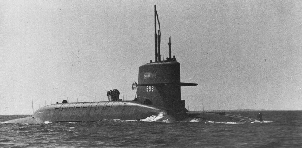
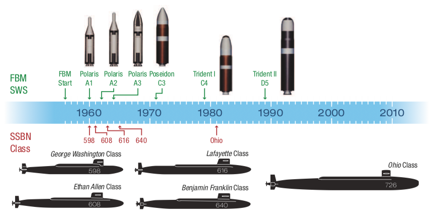
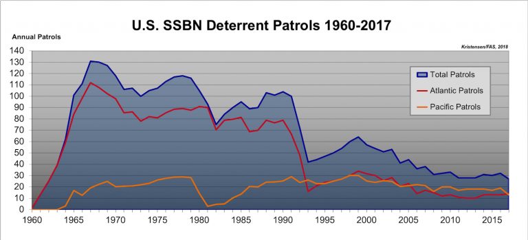
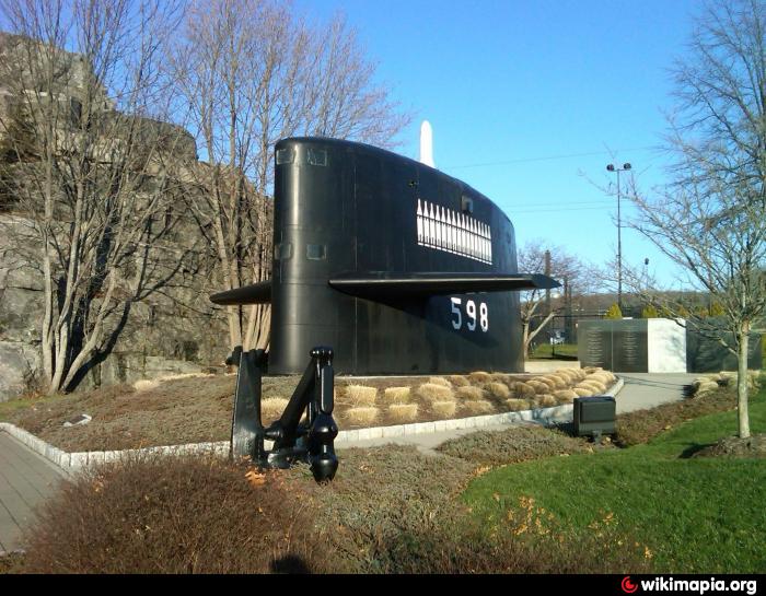
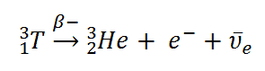


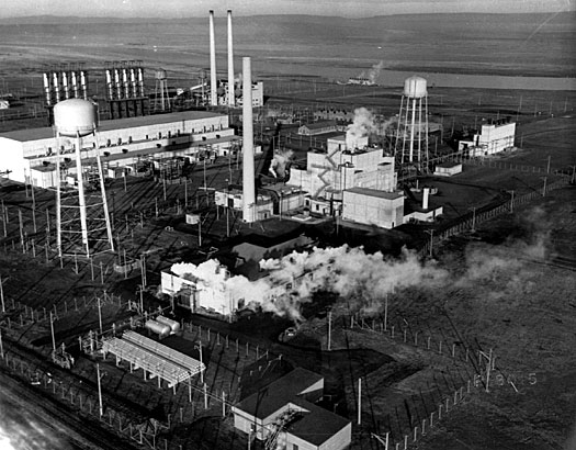
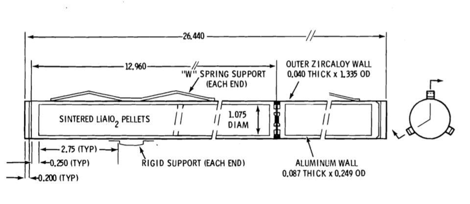

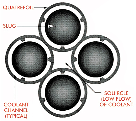
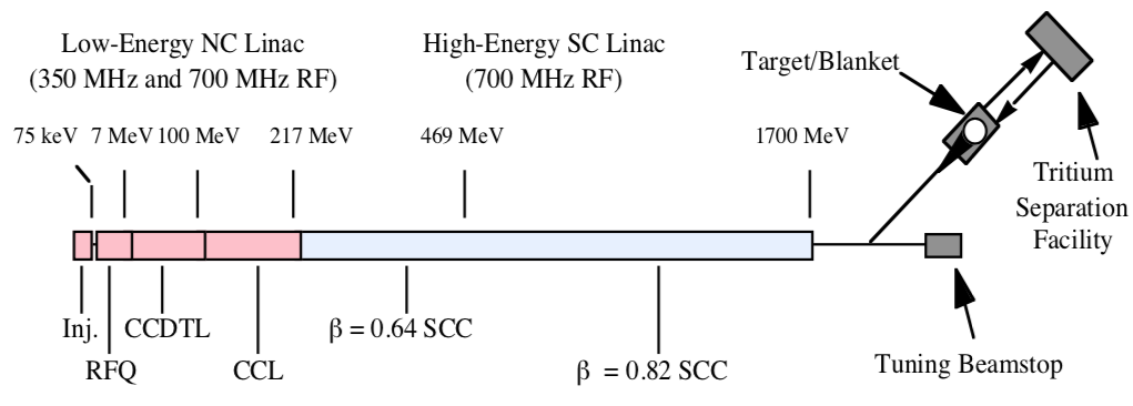
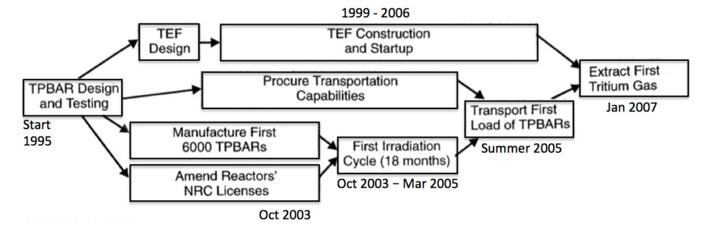
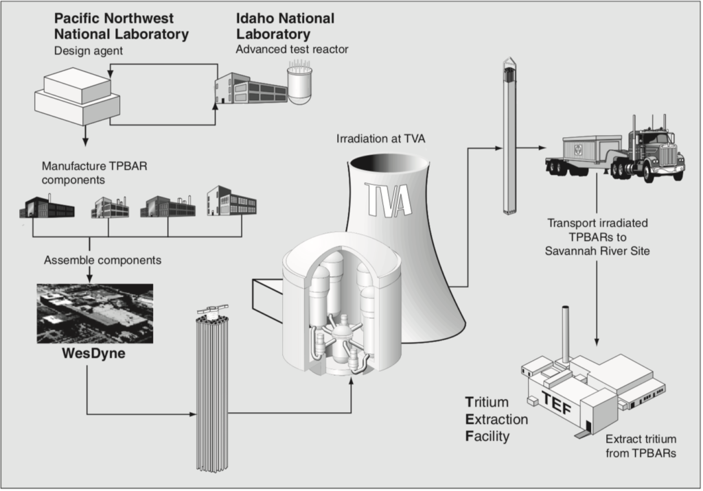
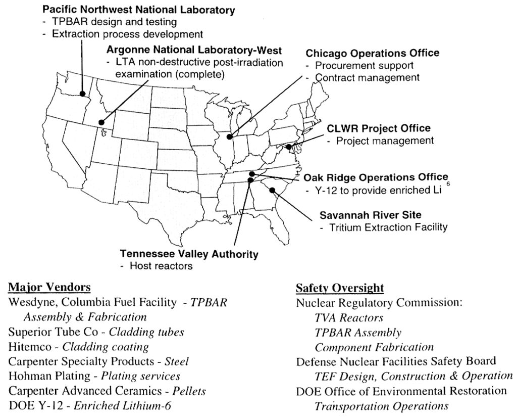

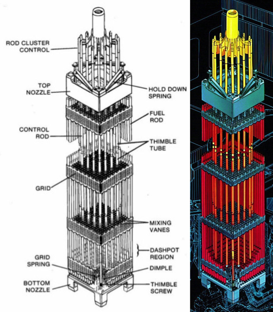
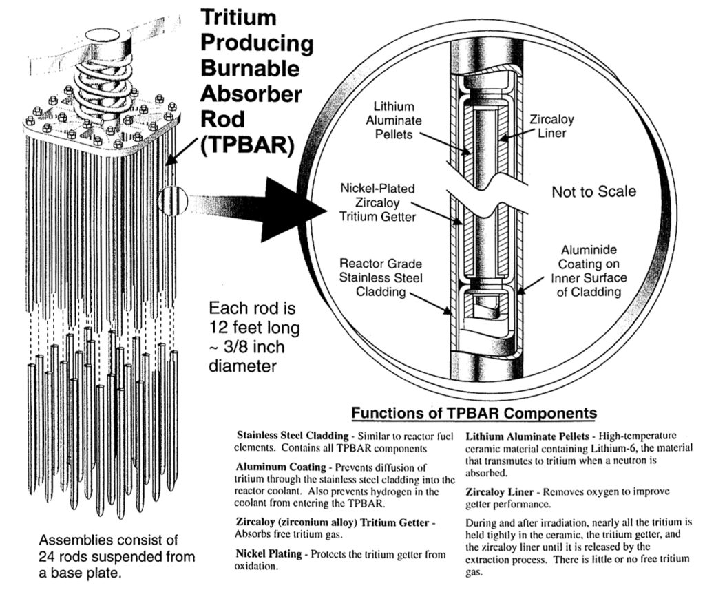
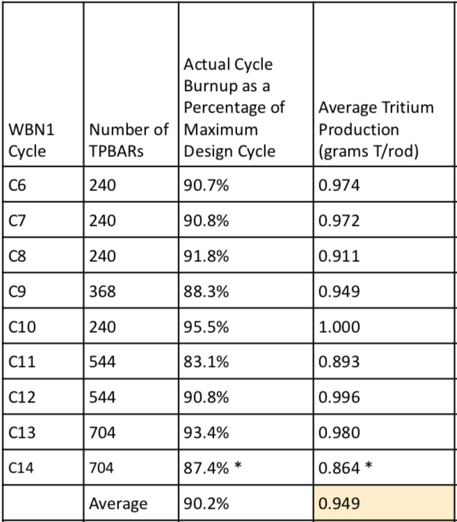
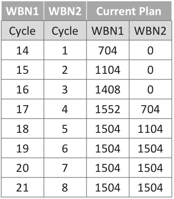
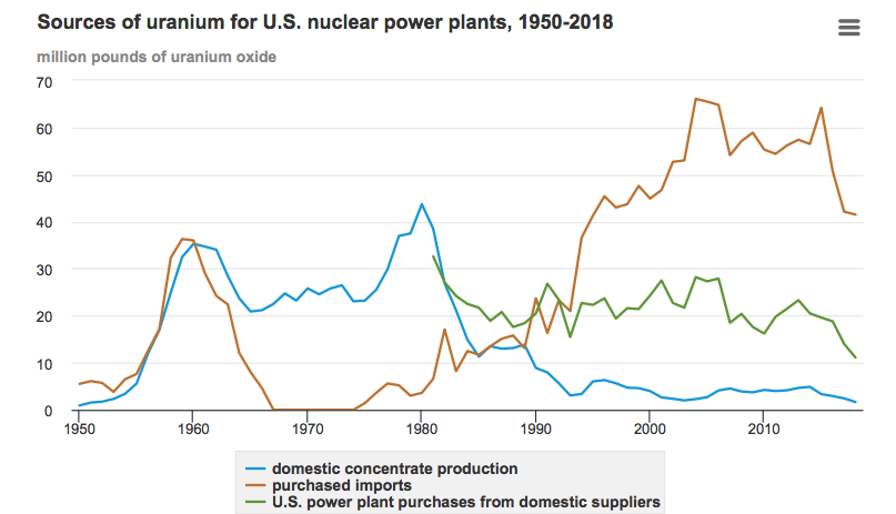
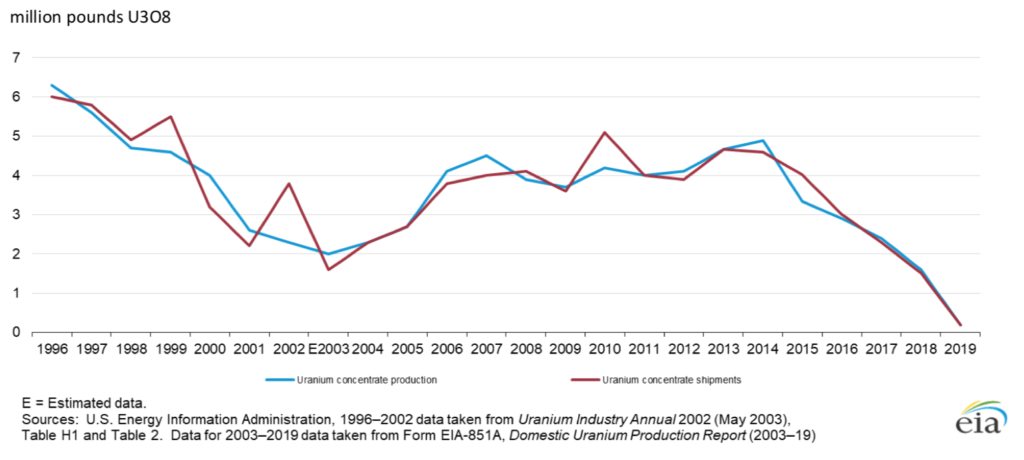
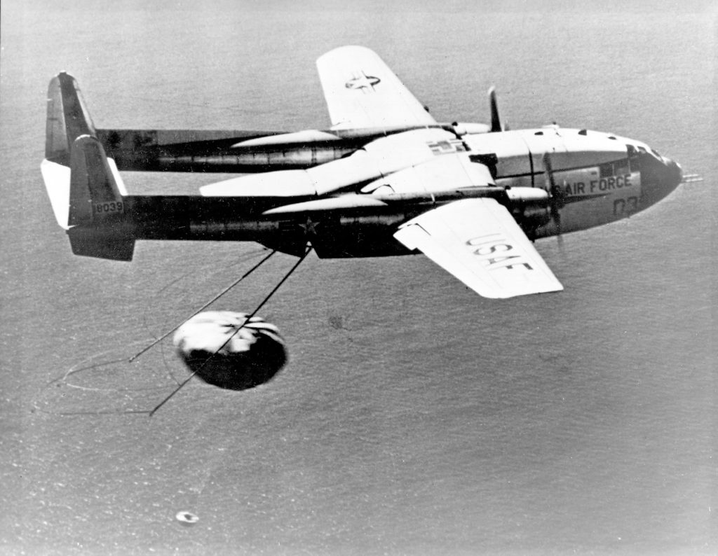
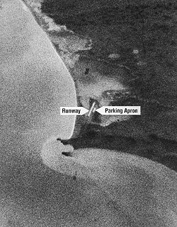
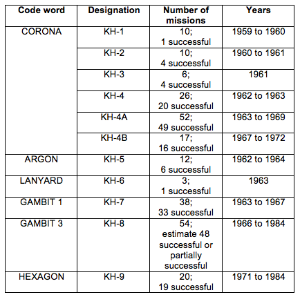
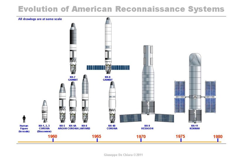
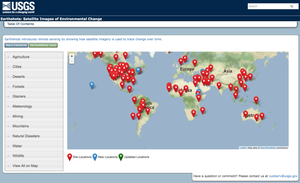
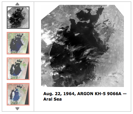
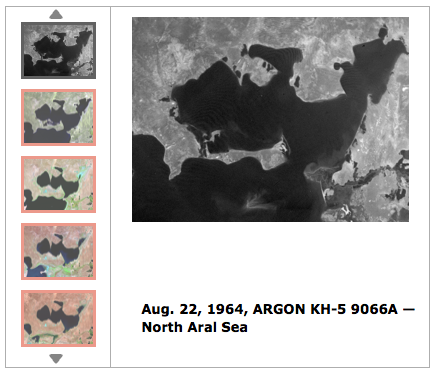
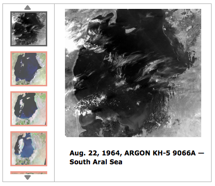
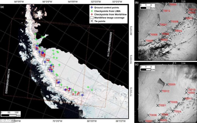

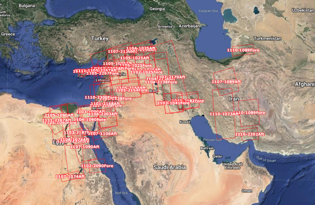
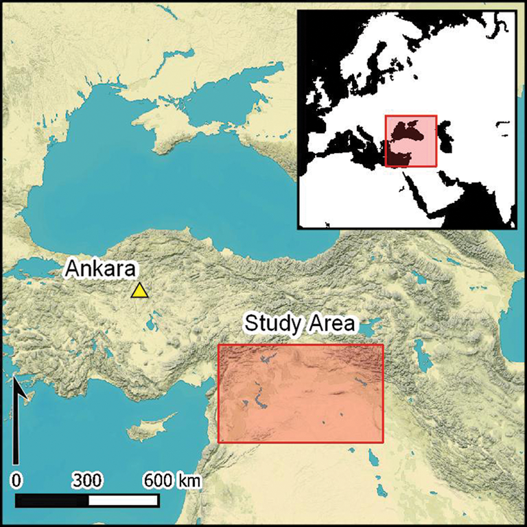
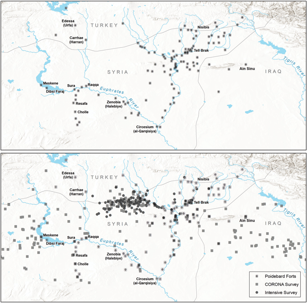
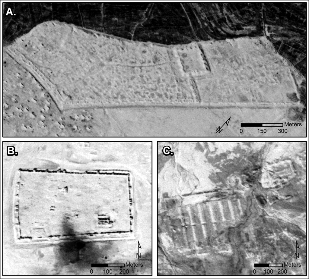
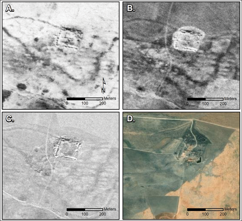


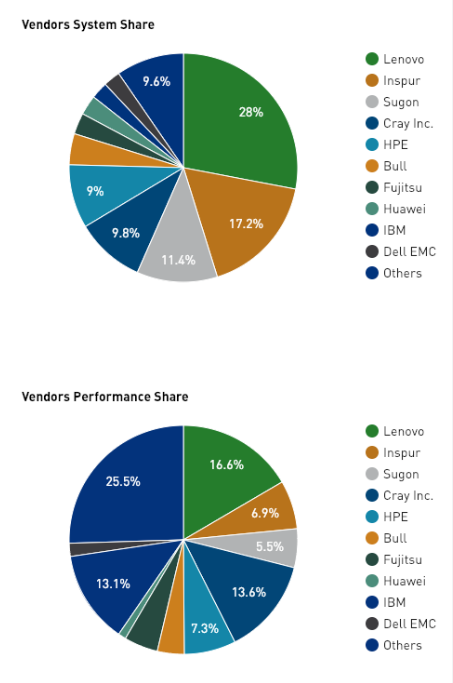
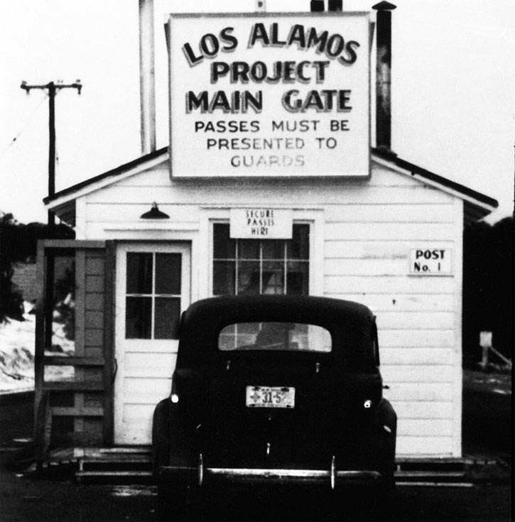
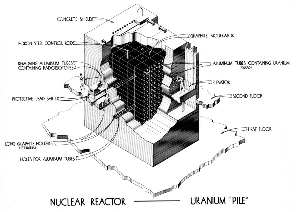
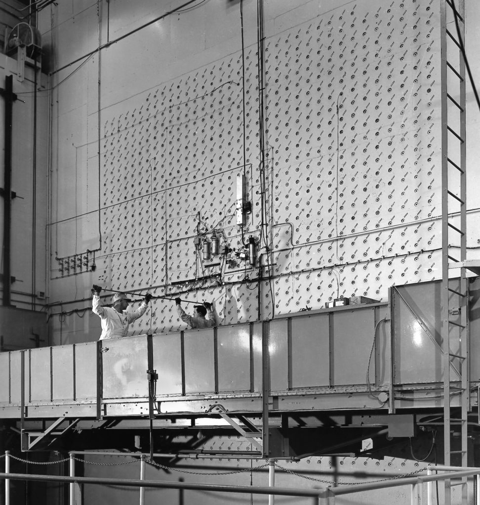
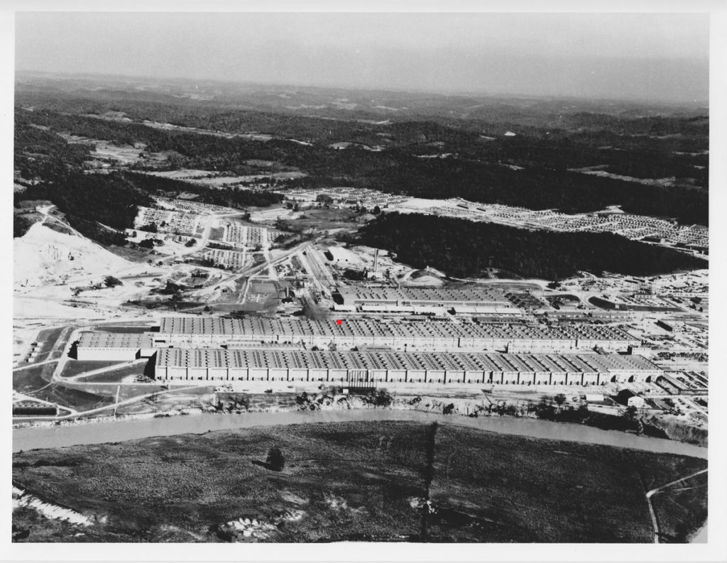
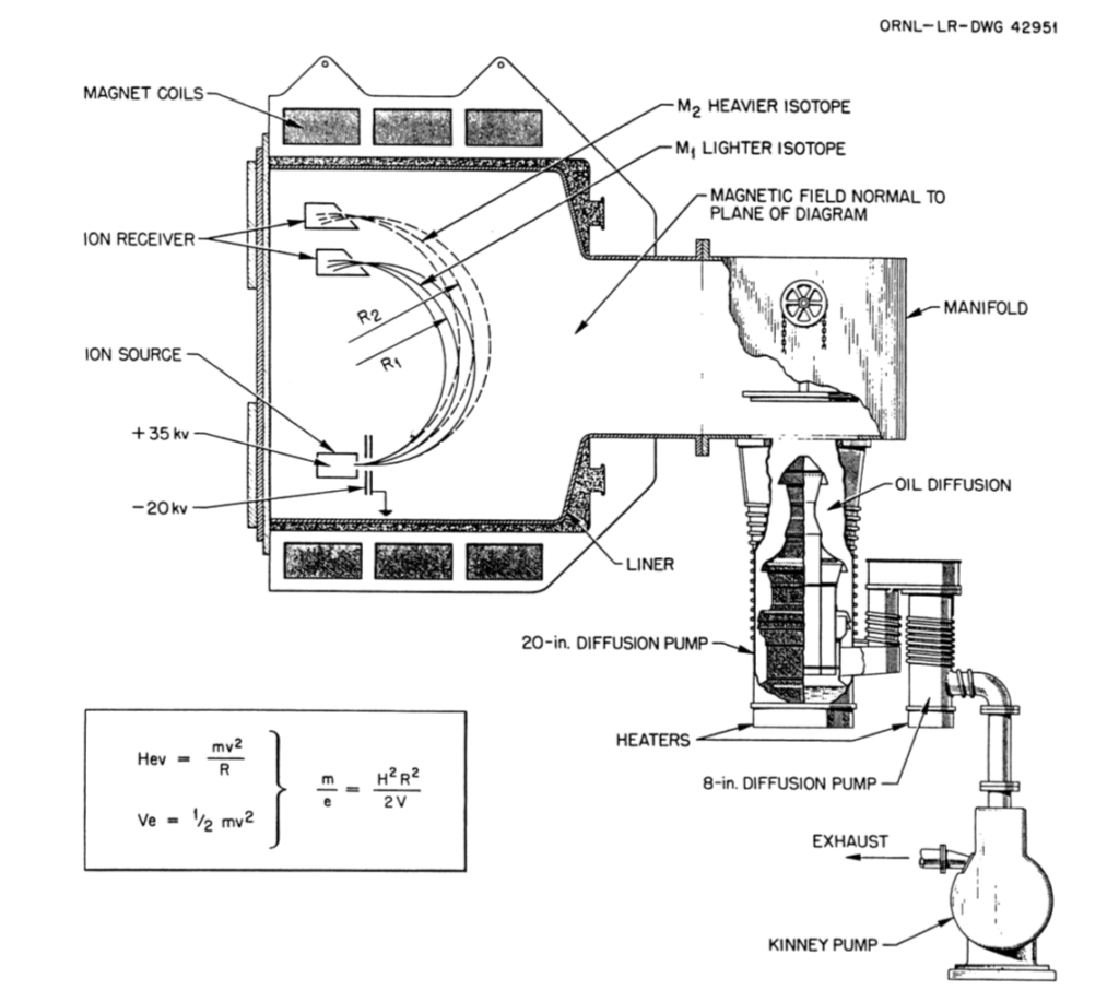
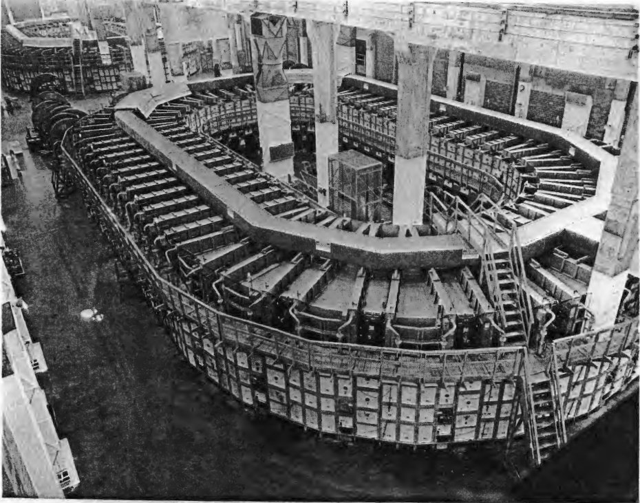
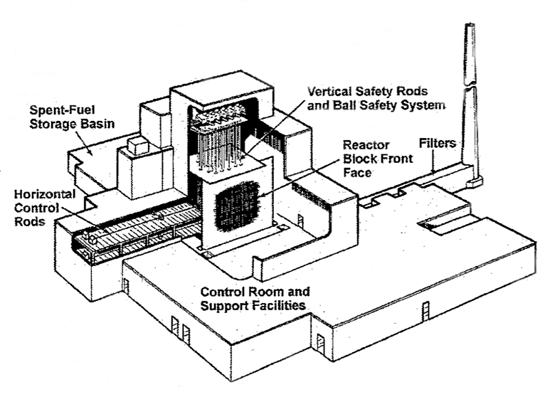
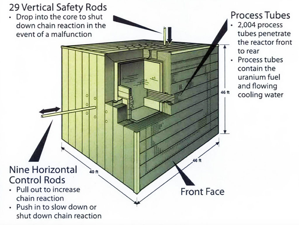
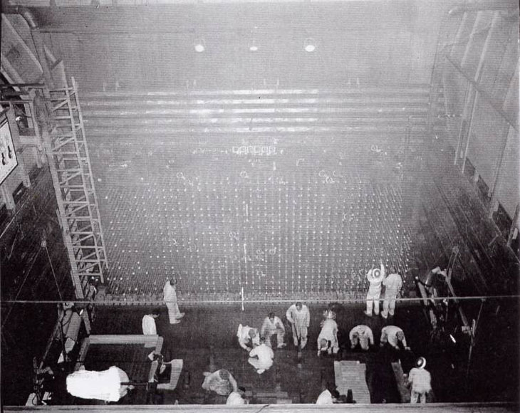
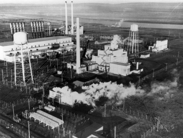
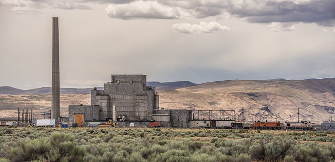
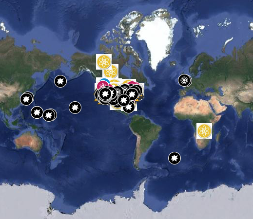
 Summit supercomputer. Source: NVIDIA
 Sierra supercomputer. Source: Lawrence Livermore National Laboratory / Randy Wong
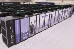 Source: LANL
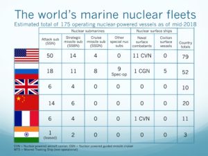 Source: two charts by author


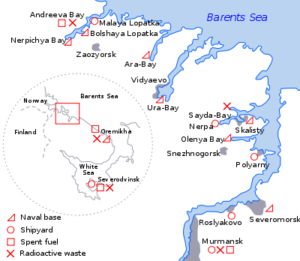


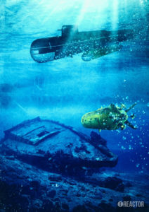


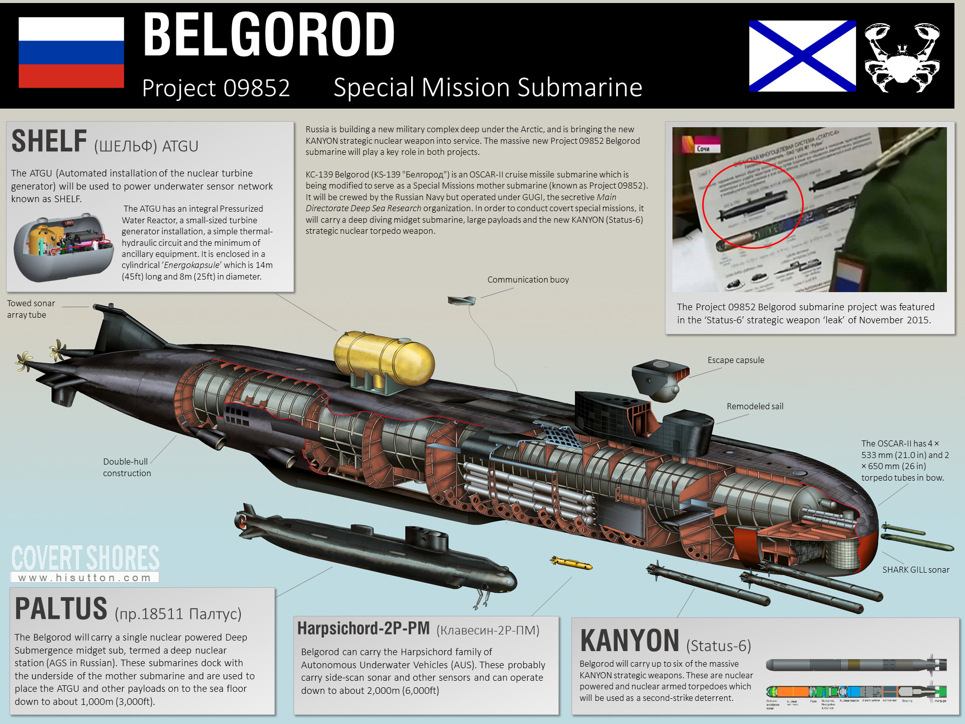