The UUM-44 SUBROC (SUBmarine-launched anti-submarine ROCket) was a 22 ft (6.7 m) long, inertially-guided, long-range weapon that consisted of a solid fuel booster rocket with a W55 thermonuclear depth charge warhead.
SUBROC on display at the Smithsonian Air & Space Museum annex, Udvar-Hazy Center. Source: National Air & Space Museum
As shown in the following diagram, SUBROC was launched horizontally from a standard submarine 21 in (533 mm) diameter torpedo tube. When the missile surfaced, the booster rocket ignited and flew toward the target. The warhead separated when the booster was expended and then flew a ballistic trajectory to the target area, where it re-entered the water and detonated at a prescribed depth.
SUBROC mission profile. Source: US NavySUBROC launch. Source: US Navy
The SUBROC had a range reported in various sources from 25 – 50 miles (40.2 – 80.5 km), roughly bracketing the range from the launching submarine to a deep water target in the first convergence zone. This deep water acoustic phenomena focuses sound from a distant target at specific distances (convergence zones), depending on a variety of hydrographic conditions, and can permit passive detection of a surface or submerged target at much longer ranges than are possible by a direct path.
Development by Goodyear Aerospace began in 1958, technical evaluation was completed in 1963, and Initial Operating Capability (IOC) aboard USS Permit (SSN-594) was achieved in 1964.
SUBROC loading on USS Plunger (SSN-595). Source: missilery.info
While SUBROC production ended in 1968, the weapon was operational for 25 years, until it was retired from the U.S. submarine fleet in 1989. The National War Memorial Registry preserves a record of a Cold War memorial plaque commemorating the SUBROC at the corner of C Street & 1st Street in Norfolk, VA.
Source: National War Memorial Registry
So what’s the connection between SUBROC and the unique 355-foot (108-meter), non-self-propelled vessel known as the FLoating Instrument Platform (FLIP), which was designed with a rather conventional bow and a long cylindrical hull that could be partially flooded at sea to enable the vessel to float vertically in the water with most of the hull submerged, like a giant spar buoy?
FLIP transitioning from horizontal to vertical. Source: New Atlas
Scripps Institute of Oceanography provides the following answer:
“Research Platform FLIP was developed to provide a stable platform to measure fine-scale fluctuations in phase and amplitude of sound waves for the U.S. Navy SUBROC (SUBmarine ROCket) program. One of the major questions concerned bearing accuracy obtained acoustically out to convergence-zone ranges. Horizontal temperature/salinity gradients in the ocean could introduce bearing errors in the volume of the ocean, and sloping bottoms could do the same for acoustic paths that interacted with the bottom. The Navy needed precise measurements to determine the effect of environmental gradients and fluctuations.
On July 23, 1962, FLIP was tested for the first time in the Dabob Bay area of the Hood Canal in Washington state on the Navy tracking range. After successfully completing trials of the flipping operation, it was towed to San Diego to commence operations in September 1962.
Many years of operations have included deployments in the Pacific as far as Hawaii and one deployment to the Atlantic. While originally intended for acoustic research, it has become a versatile platform for research in upper-ocean physical oceanography, meteorology, geophysics, and biology.”
FLIP’s bow contained the uniquely-equipped habitable spaces that enabled the crew and scientists to work when the ship aligned horizontally or vertically.
A not-so-simple double sink. Source: Scripps Institute of Oceanography
Work platforms when flipped.Source: Scripps Institute of Oceanography
FLIP in the floating dry dock ARCO at Naval Base Point Loma in the 2000s. Source: Scripps Institute of Oceanography
After an operational lifetime of more than 60 years, during which FLIP conducted more than 380 flipping operations, the unique vessel was retired and towed to a dismantling and recycling facility in Mexico in August 2023.
30 October 2024 update:
Fortunately, FLIP has been saved by the UK firm DEEP, which announced in October 2024, “..the rescued platform has made its way from Mexico, through the Panama Canal and across the Atlantic to the Mediterranean, where over the next 12 – 18 months she will be refitted and modernized in France.” You’ll find more information on DEEP’s acquisition of FLIP in the 23 October 2024 DEEP press release and the related USNI article.
For more information on SUBROC and FLIP, check out the following references:
On 15 Nov 1960, the FBM submarine USS George Washington (SSBN-598) embarked on the nation’s first Polaris nuclear deterrent patrol armed with 16 intermediate range Polaris A1 submarine launched ballistic missiles (SLBMs). This milestone occurred just 3 years 11 months after the Polaris FBM program was funded by Congress and authorized by the Secretary of Defense. The 1st deterrent patrol was completed 66 days later on 21 January 1961.
USS George Washington underway. Source: Navsource
The original US FBM submarine force consisted of 41 Polaris submarines, in five sub-classes (George Washington, Ethan Allen, Lafayette, James Madison and Benjamin Franklin), that were authorized between 1957 and l963. Through several rounds of modifications, most of these submarines were adapted to handle later versions of the Polaris SLBM (A2, A3 and A4) and some were modified to handle the Poseidon (C3) SLBM. Twelve of the James Madison- and Ben Franklin-class boats were modified the late 1970s and early 1980s to handle the long range Trident I C4 SLBMs.
A total of 1,245 Polaris deterrent patrols were made in a period of about 21 years, from the first Polaris A-1 deterrent patrol by USS George Washington in 1960, and ending with the last Polaris A-3 deterrent patrol by USS Robert E. Lee (SSBN-601), which started on 1 October 1981. By then, the remainder of the original Polaris SSBN fleet had transitioned to Poseidon (C3) and Trident I (C4) SLBMs.
The next generation of US ballistic missile submarines was the Ohio-class SSBN, 18 of which were ordered between 1974 and 1990 (one per fiscal year). The lead ship of this class, USS Ohio (SSBN 726), was commissioned in 1981 and deployed 6 September 1982 on its first strategic deterrent patrol, armed with the Trident I (C4) SLBM. Beginning with the 9th boat in class, USS Tennessee (SSBN-734), the remaining Ohio- class SSBNs were equipped originally to handle the larger Trident II (D5). Four of the early boats were upgraded to handle the Trident II (D5) missile. The earliest four, including the USS Ohio, were converted to cruise missile submarines to comply with strategic weapons treaty limits.
Evolution of the US submarine strategic nuclear deterrent fleet. Johns Hopkins APL Technical Digest, Volume 29, Number 4, 2011
The Federation of American Scientists (FAS) reported that the US Navy conducted 4,086 submarine strategic deterrent patrols between 1969 and 2017. At that time, the Navy was conducting strategic deterrent patrols at a steady rate of around 30 patrols per year. By the end of 2020, that total must be approaching 4,175 patrols.
Source: Hans Kristensen, FAS, 2018
In 2020, the US maintains a fleet of 14 Trident missile submarines armed with D5LE (life extension) SLBMs. By about 2031, the first of the new Columbia-class SSBN is expected to be ready to start its first deterrent patrol. Ohio-class SSBNs will be retired on a one-for-one bases when the new Columbia-class SSBNs are delivered to the fleet and ready to assume deterrent patrol duties.
The USS George was defueled and declared scrapped in September 1998. Owing to her place in history as the first US ballistic missile submarine and her successful completion of 55 deterrent patrols in both the Atlantic & Pacific Oceans, the George Washington’s sail was preserved and returned to New London, CT where it is now displayed outside of the gates of the US Submarine Force Library and Museum.
The USS George Washington’s sail on display outside the US Submarine Force Library and Museum in New London, CT. Source: Wikimapia
John Gibson & Stephen Yanek, “The Fleet Ballistic Missile Strategic Weapon System: APL’s Efforts for the U.S. Navy’s Strategic Deterrent System and the Relevance to Systems Engineering,” Johns Hopkins APL Technical Digest, Volume 29, Number 4, 2011: https://www.jhuapl.edu/Content/techdigest/pdf/V29-N04/29-04-Gibsonl.pdf
On 19 January 1942, US President Franklin D. Roosevelt approved the production of an atomic bomb. At that time, most of the technology for producing an atomic bomb still needed to be developed and the US had very little infrastructure in place to support that work.
The Manhattan Engineer District (MED, aka the “Manhattan Project”) was responsible for the research, design, construction and operation of the early US nuclear weapons complex and for delivering atomic bombs to the US Army during World War II (WW II) and in the immediate post-war period. The Manhattan Project existed for just five years. In 1943, 75 years ago, the Manhattan Project transitioned from planning to construction and initial operation of the first US nuclear weapons complex facilities. Here’s a very brief timeline for the Manhattan Project.
13 August 1942: The Manhattan Engineer District was formally created under the leadership of U.S. Army Colonel Leslie R. Groves.
2 December 1942: A team led by Enrico Fermi achieved the world’s first self-sustaining nuclear chain reaction in a graphite-moderated, natural uranium fueled reactor known simply as Chicago Pile-1 (CP-1).
1943 – 1946: The Manhattan Project managed the construction and operation of the entire US nuclear weapons complex.
16 July 1945: The first nuclear device was successfully tested at the Trinity site near Alamogordo, NM, less than three years after the Manhattan Project was created.
6 & 9 August 1945: Atomic bombs were employed by the US against Japan, contributing to ending World War II.
1 January 1947: The newly formed, civilian-led Atomic Energy Commission (AEC) took over management and operation of all research and production facilities from the Manhattan Engineer District.
25 August 1947: The Manhattan Engineer District was abolished.
The WW II nuclear weapons complex was the foundation for the early US post-war nuclear weapons infrastructure that evolved significantly over time to support the US mutually-assured destruction strategy during the Cold War with the Soviet Union. Today, the US nuclear weapons complex continues to evolve as needed to perform its critical role in maintaining the US nuclear deterrent capability.
2. A Closer Look at the Manhattan Project Timeline
You’ll find a comprehensive, interactive timeline of the Manhattan Project on the Department of Energy’s (DOE) OSTI website at the following link:
The Atomic Heritage Foundation is dedicated to “supporting the Manhattan Project National Historical Park and capturing the memories of the people who harnessed the energy of the atom.” Their homepage is here:
The Manhattan Project National Historical Park was authorized by Congress in December 2014 and subsequently was approved by the President to commemorate the Manhattan Project. The Manhattan Project National Historical Park is an extended “park” that currently is comprised of three distinct DOE sites that each had different missions during WW II:
Los Alamos, New Mexico: Nuclear device design, test and production
Oak Ridge, Tennessee: Enriched uranium production
Hanford, Washington: Plutonium production
On 10 November 2015, a memorandum of agreement between DOE and the National Park Service (NPS) established the park and the respective roles of DOE and NPS in managing the park and protecting and presenting certain historic structures to the public.
You’ll find the Manhattan Project National Historical Park website here:
Following is a brief overview of the three sites that currently comprise the Manhattan Project National Historical Park.
3.1. Los Alamos, New Mexico
Los Alamos Laboratory was established 75 years ago, in early 1943, as MED Site Y, under the direction of J. Robert Oppenheimer. This was the Manhattan Project’s nuclear weapons laboratory, which was created to consolidate in one secure, remote location most of the research, design, development and production work associated producing usable nuclear weapons to the US Army during WW II.
Los Alamos Laboratory main gate circa 1944. Source: Los Alamos National Laboratory
The first wave of scientists began arriving at Los Alamos Laboratory in April 1943. Just 27 months later, on 16 July 1945, the world’s first nuclear device was detonated 200 miles south of Los Alamos at the Trinity Site near Alamogordo, NM. This was the plutonium-fueled, implosion-type device code named “Gadget.”
During WW II, the Los Alamos Laboratory produced three atomic bombs:
One uranium-fueled, gun-type atomic bomb code named “Little Boy” was produced. This was the atomic bomb dropped on Hiroshima, Japan on 6 August 1945, making it the first nuclear weapon used in warfare. This atomic bomb design was not tested before it was used operationally.
Two plutonium-fueled, implosion-type atomic bombs code named “Fat Man” were produced. These bombs were very similar to Gadget. One of the Fat Man bombs was dropped on Nagasaki, Japan on 9 August 1945. The second Fat Man bomb could have been used during WW II, but it was not needed after Japan announced its surrender on 15 August 1945.
The highly-enriched uranium for the Little Boy bomb was produced by the enrichment plants at Oak Ridge. The plutonium for Gadget and the two Fat Man bombs was produced by the production reactors at Hanford.
Three historic sites are on Los Alamos National Laboratory property and currently are not open to the public:
Gun Site Facilities: three bunkered buildings (TA-8-1, TA-8-2, and TA-8-3), and a portable guard shack (TA-8-172).
V-Site Facilities: TA-16-516 and TA-16-517 V-Site Assembly Building
Pajarito Site: TA-18-1 Slotin Building, TA-8-2 Battleship Control Building, and the TA-18-29 Pond Cabin.
You’ll find information on the Manhattan Project National Historical Park sites at Los Alamos here:
Land acquisition was approved in 1942 for planned uranium “atomic production plants” in the Tennessee Valley. The selected site officially became the Clinton Engineer Works (CEW) in January 1943 and was given the MED code name Site X. This is where MED and its contractors managed the deployment during WW II of the following three different uranium enrichment technologies in three separate, large-scale industrial process facilities:
Liquid thermal diffusion process, based on work by Philip Abelson at Naval Research Laboratory and the Philadelphia Naval Yard. This process was implemented at S-50, which produced uranium enriched to < 2 at. % U-235.
Gaseous diffusion process, based on work by Harold Urey at Columbia University. This process was implemented at K-25, which produced uranium enriched to about 23 at. % U-235 during WW II.
Electromagnetic separation process, based on Ernest Lawrence’s invention of the cyclotron at the University of California Berkeley in the early 1930s. This process was implemented at Y-12 where the final output was weapons-grade uranium.
The Little Boy atomic bomb used 92.6 pounds (42 kg) of highly enriched uranium produced at Oak Ridge with contributions from all three of these processes.
The nearby township was named Oak Ridge in 1943, but the nuclear site itself was not officially renamed Oak Ridge until 1947.
The three Manhattan Project National Historical Park sites at Oak Ridge are:
X-10 Graphite Reactor National Historic Landmark
K-25 complex
Y-12 complex: Buildings 9731 and 9204-3
The S-50 Thermal Diffusion Plant was dismantled in the late 1940s. This site is not part of the Manhattan Project National Historical Park.
Following is a brief overview of X-10, K-25 and Y-12 historical sites. There’s much more information on the Manhattan Project National Historical Park sites at Oak Ridge here:
X-10 was the world’s second nuclear reactor (after the Chicago Pile, CP-1) and the first reactor designed and built for continuous operation. It was intended to produce the first significant quantities of plutonium, which were used by scientists at Los Alamos to characterize plutonium and develop the design of a plutonium-fueled atomic bomb.
X-10 was a large graphite-moderated, natural uranium fueled reactor that originally had an continuous design power rating of 1.0 MWt, which later was raised to 3.5 MWt. Originally, it was intended to be a prototype for the much larger plutonium production reactors being planned for Hanford. The selection of air cooling for X-10 enabled this reactor to be deployed more rapidly, but limited its value as a prototype for the future water-cooled plutonium production reactors.
The X-10 reactor core was comprised of graphite blocks arranged into a cube measuring 24 feet (7.3 meters) on each side. The core was surrounded by several feet of high-density concrete and other material to provide radiation shielding. The core and shielding were penetrated by 1,248 horizontal channels arranged in 36 rows. Each channel served to position up to 54 fuel slugs in the core and provide passages for forced air cooling of the core. Each fuel slug was an aluminum clad, metallic natural uranium cylinder measuring 4 inches (10.16 cm) long x 1.1 inches (2.79 cm) in diameter. New fuel slugs were added manually at the front face (the loading face) of the reactor and irradiated slugs were pushed out through the back face of the reactor, dropping into a cooling water pool. The reactor was controlled by a set of vertical control rods.
The basic geometry of the X-10 reactor is shown below.
X-10 Graphite Reactor general arrangement. Source: Department of Energy / Oak Ridge via https://en.wikipedia.org/Workers load fuel slugs into the X-10 Graphite Reactor circa 1952. Source: US Army / Manhattan Engineer District – Ed Westcott / American Museum of Science and Energy / https://en.wikipedia.org/
Site construction work started 75 years ago, on 27 April 1943. Initial criticality occurred less than seven months later, on 4 November 1943.
Plutonium was recovered from irradiated fuel slugs in a pilot-scale chemical separation line at Oak Ridge using the bismuth phosphate process. In April 1944, the first sample (grams) of reactor-bred plutonium from X-10 was delivered to Los Alamos. Analysis of this sample led Los Alamos scientists to eliminate one candidate plutonium bomb design (the “Thin Man” gun-type device) and focus their attention on the Fat Man implosion-type device. X-10 operated as a plutonium production reactor until January 1945, when it was turned over to research activities. X-10 was permanently shutdown on 4 November 1963, and was designated a National Historic Landmark on 15 October 1966.
K-25 Gaseous Diffusion Plant
Preliminary site work for the K-25 gaseous diffusion plant began 75 years ago, in May 1943, with work on the main building starting in October 1943. The six-stage pilot plant was ready for operation on 17 April 1944.
K-25 site circa 1944. Source: http://k-25virtualmuseum.org/timeline/index.html
The K-25 gaseous diffusion plant feed material was uranium hexafluoride gas (UF6) from natural uranium and slightly enriched uranium from both the S-50 liquid thermal diffusion plant and the first (Alpha) stage of the Y-12 electromagnetic separation plant. During WW II, the K-25 plant was capable of producing uranium enriched up to about 23 at. % U-235. This product became feed material for the second (Beta) stage of the Y-12 electromagnetic separation process, which continued the enrichment process and produced weapons-grade U-235.
As experience with the gaseous diffusion process improved and additional cascades were added, K-25 became capable of delivering highly-enriched uranium after WW II.
You can take a virtual tour of K-25, including its decommissioning and cleanup, here:
Construction on the second Oak Ridge gaseous diffusion plant, K-27, began on 3 April 1945. This plant became operational after WW II. By 1955, the K-25 complex had grown to include gaseous diffusion buildings K-25, K-27, K-29, K-31 and K-33 that comprised a multi-building, enriched uranium production chain collectively known as the Oak Ridge Gaseous Diffusion Plant (ORGDP). Operation of the ORGDP continued until 1985.
Additional post-war gaseous diffusion plants based on the technology developed at Oak Ridge were built and operated in Paducah, KY (1952 – 2013) and Portsmouth, OH (1954 – 2001).
Y-12 Electromagnetic Separation Plant
In 1941, Earnest Lawrence modified the 37-inch (94 cm) cyclotron in his laboratory at the University of California Berkeley to demonstrate the feasibility of electromagnetic separation of uranium isotopes using the same principle as a mass spectrograph.
The initial industrial-scale design agreed in 1942 was called an Alpha (α) calutron, which was designed to enrich natural uranium (@ 0.711 at.% U-235) to >10 at.% U-235. The later Beta (β) calutron was designed to further enrich the output of the Alpha calutrons, as well as the outputs from the K-25 and S-50 processes, and produce weapons-grade uranium at >88 at.% U-235.
The calutrons required large magnet coils to establish the strong electromagnetic field needed to separate the uranium isotopes U-235 and U-238. The shape of the magnet coils for both the Alfa and Beta calutrons resembled a racetrack, with many individual calutron modules (aka “tanks”) arranged side-by-side around the racetrack. At Y-12, there were nine Alpha calutron “tracks” (5 x Alpha-1 and 4 x Alpha-2 tracks), each with 96 calutron modules (tanks), for a total of 864 Alpha calutrons. In addition, there were eight Beta calutron tracks, each with 36 calutron modules, for a total of 288 beta calutrons, only 216 of which ever operated.
Due to wartime shortages of copper, the Manhattan Project arranged a loan from the Treasury Department of about 300 million Troy ounces (10,286 US tons) of silver for use in manufacturing the calutron magnet coils. A general arrangement of a Beta calutron module (tank) is shown in the following diagram, which also shows the isotope flight paths from the uranium tetrachloride (UCl4) ion source to the ion receivers. Separated uranium was recovered by burning the graphite ion receivers and extracting the metallic uranium from the ash.
General arrangement of a Beta calutron module (tank). Source: Oak Ridge drawing 42951, via Yergey & Yergey, 1997An Alpha calutron “racetrack” comprised of 96 individual calutron modules (tanks). Source: Department of Energy, Oak Ridge via https://commons.wikimedia.org/
Construction of Buildings 9731 and 9204-3 at the Y-12 complex began 75 years ago, in February 1943. By February 1944, initial operation of the Alpha calutrons had produced only 0.44 pounds (0.2 kg) of U-235 @ 12 at.%. By August 1945, the Y-12 Beta calutrons had produced the 92.6 pounds (42 kg) of weapons-grade uranium needed for the Little Boy atomic bomb.
After WW II, the silver was recovered from the calutron magnet coils and returned to the Treasury Department.
3.3. Hanford, Washington
On January 16, 1943, General Leslie Groves officially endorsed Hanford as the proposed plutonium production site, which was given the MED code name Site W. The plan was to construct three large graphite-moderated, water-cooled plutonium production reactors, designated B, D, and F, in along the Columbia River. The Hanford site also would include a facility for manufacturing the new uranium fuel slugs for the reactors as well as chemical separation plants and associated facilities to recover and process plutonium from the irradiated uranium slugs.
After WW II, six more plutonium production reactors were built at Hanford along with additional plutonium and nuclear waste processing and storage facilities.
The Manhattan Project National Historical Park sites at Hanford are:
B Reactor, which has been a National Historic Landmark since 19 August 2008
The previous Hanford High School in the former Town of Hanford and Hanford Construction Camp Historic District
Bruggemann’s Agricultural Warehouse Complex
White Bluffs Bank and Hanford Irrigation District Pump House
A brief overview of the B Reactor and the other Hanford production reactors is provided below. There’s more information on the Manhattan Project National Historical Park sites at Hanford here:
The Manhattan Project National Historical Park does not include the Hanford chemical separation plants and associated plutonium facilities in the 200 Area, the uranium fuel production plant in the 300 Area, or the other eight plutonium production reactors that were built in the 100 Area. Information on all Hanford facilities, including their current cleanup status, is available on the Hanford website here:
The B Reactor at the Hanford Site was the world’s first full-scale reactor and the first of three plutonium production reactor of the same design that became operational at Hanford during WW II. B Reactor and the similar D and F Reactors were significantly larger graphite-moderated reactor than the X-10 Graphite Reactor at Oak Ridge. The rectangular reactor core measured 36 feet (11 m) wide x 36 feet (11 m) tall x 28 feet (8.53 m) deep, surrounded by radiation shielding. These reactors were fueled by aluminum clad, metallic natural fuel slugs measuring 8 inches (20.3 cm) long x 1.5 inches (3.8 cm) in diameter. As with the X-10 Graphite Reactor, new fuel slugs were inserted into process tubes (fuel channels) at the front face of the reactor. The irradiated fuel slugs were pushed out of the fuel channels at the back face of the reactor, falling into a water pool to allow the slugs to cool before further processing for plutonium recovery.
Reactor cooling was provided by the once-through flow of filtered and processed fresh water drawn from the Columbia River. The heated water was discharged from the reactor into large retention basins that allowed some cooling time before the water was returned to the Columbia River.
Hanford production reactor general arrangement (Typical of B, D & F Reactor). Source: DOE/RL-97-1047, Department of Energy (DOE)Hanford production reactor core general arrangement (Typical of B, D, F, H, DR and C). Source: DOEThe front face (loading face) of B Reactor. Source: DOE
Construction of B Reactor began 75 years ago, in October 1943, and fuel loading started 11 months later, on September 13, 1944. Initial criticality occurred on 26 September 1944, followed shortly by operation at the initial design power of 250 MWt.
B Reactor was the first reactor to experience the effects of xenon poisoning due to the accumulation of Xenon (Xe-135) in the uranium fuel. Xe-135 is a decay product of the relatively short-lived (6.7 hour half-life) fission product iodine I-135. With its very high neutron cross-section, Xe-135 absorbed sufficient neutrons to significantly, and unexpectedly, reduce B Reactor power. Fortunately, DuPont had added more process tubes (a total of 2004) than called for in the original design of B Reactor. After the xenon poisoning problem was understood, additional fuel was loaded, providing the core with enough excess reactivity to override the neutron poisoning effects of Xe-135.
On 3 February 1945, the first batch of B Reactor plutonium was delivered to Los Alamos, just 10 months after the first small plutonium sample from the X-10 Graphite Reactor had been delivered.
B Reactor plutonium production complex at Hanford, in its heyday. Source: DOEB Reactor at Hanford today. Source: DOE
Regular plutonium deliveries from the Hanford production reactors provided the plutonium needed for the first ever nuclear device (the Gadget) tested at the Trinity site near Alamogordo, NM on 16 July 1945, as well as for the Fat Man atomic bomb dropped on Nagasaki, Japan on 9 August 1945 and an unused second Fat Man atomic bomb. These three devices each contained about 13.7 pounds (6.2 kilograms) of weapons-grade plutonium produced in the Hanford production reactors.
From March 1946 to June 1948, B Reactor was shut down for maintenance and modifications. In March 1949, B Reactor began the first tritium production campaign, irradiating targets containing lithium and producing tritium for hydrogen bombs.
By 1963, B Reactor was permitted to operate at a maximum power level of 2,090 MWt. B Reactor continued operation until 29 January 1968, when it was ordered shut down by the Atomic Energy Commission. Because of its historical significance, B Reactor was given special status that allows it to be open for public tours as part of the Manhattan Project National Historical Park.
The Other WW II Production Reactors at the Hanford Site: D & F
During WW II, three plutonium reactors of the same design were operational at Hanford: B, D and F. All had an initial design power rating of 250 MWt and by 1963 all were permitted to operate at a maximum power level of 2,090 MWt.
D Reactor: This was the world’s second full-scale nuclear reactor. It became operational in December 1944, but experienced operational problems early in life due to growth and distortion of its graphite core. After developing a process for controlling graphite distortion, D Reactor operated successfully through June 1967.
F Reactor: This was the third of the original three production reactors at Hanford. It became operational in February 1945 and ran for more than twenty years until it was shut down in June1965.
D and F Reactors currently are in “interim safe storage,” which commonly is referred to as “cocooned.” These reactor sites are not part of the Manhattan Project National Historical Park.
Post-war Production Reactors at Hanford: H, DR, C, K-West, K-East & N
After WW II, six additional plutonium production reactors were built and operated at Hanford. The first three, named H, DR and C, were very similar in design to the B, D and F Reactors. The next two, K-West and K-East, were of similar design, but significantly larger than their predecessors. The last reactor, named N, was a one-of-a kind design.
H Reactor: This was the first plutonium production reactor built at Hanford after WW II. It became operational in October 1949 with a design power rating of 400 MWt and by 1963 was permitted to operate at a maximum power level of 2,090 MWt. It operated for 15 years before being permanently shut down in April 1965.
DR Reactor: This reactor originally was planned as a replacement for the D Reactor and was built adjacent to the D Reactor site. DR became operational in October 1950 with an initial design power rating of 250 MWt. It operated in parallel with D Reactor for 14 years, and by 1963 was permitted to operate at the same maximum power level of 2,090 MWt. DR was permanently shut down in December 1964.
C Reactor: Reactor construction started June 1951 and it was completed in November 1952, operating initially at a design power of 650 MWt. By 1963, C Reactor was permitted to operate at a maximum power level of 2,310 MWt. It operated for sixteen years before being shut down in April 1969. C Reactor was the first reactor at Hanford to be placed in interim safe storage, in 1998.
K-West & K-East Reactors: These larger reactors differed from their predecessors mainly in the size of the moderator stack, the number, size and type of process tubes (3,220 process tubes), the type of shielding and other materials employed, and the addition of a process heat recovery system to heat the facilities. These reactors were built side-by-side and became operational within four months of each other in 1955: K-West in January and K-East in April. These reactors initially had a design power of 1,800 MWt and by 1963 were permitted to operate at a maximum power level of 4,400 MWt before an administrative limit of 4,000 MWt was imposed by the Atomic Energy Commission. The two reactors ran for more than 15 years. K-West was permanently shut down in February 1970 followed by K-East in January 1971.
N Reactor: This was last of Hanford’s nine plutonium production reactors and the only one designed as a dual-purpose reactor capable of serving as a production reactor while also generating electric power for distribution to the external power grid. The N Reactor had a reactor design power rating of 4,000 MWt and was capable of generating 800 MWe. The N Reactor also was the only Hanford production reactor with a closed-loop primary cooling system. Plutonium production began in 1964, two years before the power generating part of the plant was completed in 1966. N Reactor operated for 24 years until 1987, when it was shutdown for routine maintenance. However, it never restarted, instead being placed in standby status by DOE and then later retired.
Four of these reactors (H, DR, C and N) are in interim safe storage while the other two (K-West and K-East) are being prepared for interim safe storage. None of these reactor sites are part of the Manhattan Project National Historical Park.
The Federation of American Scientists (FAS) reported that the nine Hanford production reactors produced 67.4 metric tons of plutonium, including 54.5 metric tons of weapons-grade plutonium, through 1987 when the last Hanford production reactor (N Reactor) was shutdown.
4. Other Manhattan Project Sites
There are many MED sites that are not yet part of the Manhattan Project National Historical Park. You’ll find details on all of the MED sites on the American Heritage Foundation website, which you can browse at the following link:
Another site worth browsing is the interactive world map created by the ALSOS Digital Library for Nuclear Issues on Google Maps to show the locations and provide information on offices, mines, mills, plants, laboratories, and test sites of the US nuclear weapons complex from World War II to 2016. The map includes over 300 sites, including the Manhattan Project sites. I think you’ll enjoy exploring this interactive map.
Greene, Sherrell R., “A diamond in Dogpatch: The 75th anniversary of the Graphite Reactor – Part 2: The Postwar Years,” American Nuclear Society, December 2018 www.ans.org/pubs/magazines/download/a_1139
“Uranium Enrichment Processes Directed Self-Study Course, Module 5.0: Electromagnetic Separation (Calutron) and Thermal Diffusion,” US Nuclear Regulatory Commission Technical Training Center, 9/08 (Rev 3) https://www.nrc.gov/docs/ML1204/ML12045A056.pdf
“Uranium Enrichment Processes Directed Self-Study Course, Module 2.0: Gaseous Diffusion,” US Nuclear Regulatory Commission Technical Training Center, 9/08 (Rev 3) https://www.nrc.gov/docs/ML1204/ML12045A050.pdf
Hanford site, plutonium production reactors and processing facilities:
“Hanford Site Historical District: History of the Plutonium Production Facilities 1943-1990,” DOE/RL-97-1047, Department of Energy, Hanford Cultural and Historical Resources Program, June 2002 https://www.osti.gov/servlets/purl/807939
“Operating Limits – Hanford Production Reactors,” HW-76327, Research and Engineering Operation, Irradiation Processing Department, 5 November 1963 https://www.osti.gov/servlets/purl/10189795
“Hanford’s Historic B Reactor – Presentation to PNNL Open World Forum March 20, 2009,” HNF-40918-VA, Department of Energy, 2009 https://www.osti.gov/servlets/purl/951760
The I. V. Kurchatov Institute of Atomic Energy in Moscow was founded 75 years ago, in 1943, and is named for its founder, Soviet nuclear physicist Igor Vasilyevich Kurchatov. Until 1955, the Institute was a secret organization known only as “Laboratory No. 2 of the USSR Academy of Sciences.” The initial focus of the Institute was the development of nuclear weapons.
Kurchatov Institute 75thanniversary on Russian commemorative postage stamp. https://en.wikipedia.org/
I. V. Kurchatov and the team of scientists and engineers at the Institute led or supported many important historical Soviet nuclear milestones, including:
25 December 1946: USSR’s F-1 (Physics-1) reactor achieved initial criticality at Kurchatov Institute. This was the 1st reactor built and operated outside the US.
10 June 1948: USSR’s 1st plutonium production reactor achieved initial criticality (Unit A at Chelyabinak-65). The reactor was designed under the leadership of N. A. Dollezhal.
29 August 1949: USSR’s 1st nuclear device, First Lightning [aka RDS-1, Izdeliye 501 (device 501) and Joe 1], was detonated at the Semipalatinsk test site in what is now Kazakhstan. This was the 1st nuclear test other than by the US.
27 June 1954: World’s 1st nuclear power plant, AM-1 (aka APS-1), was commissioned and connected to the electrical grid, delivering power in Obninsk. AM-1 was designed under the leadership of N. A. Dollezhal.
22 November 1955: USSR’s 1st thermonuclear device (RDS-37, a two-stage device) was detonated at the Semipalatinsk test site. This also was the world’s 1stair-dropped thermonuclear device.
5 December 1957: USSR’s 1st nuclear-powered icebreaker, Lenin, was launched. This also was the world’s 1st nuclear-powered surface ship.
4 July 1958: USSR’s 1st nuclear-powered submarine, Project 627 SSN K-3, Leninskiy Komsomol, made its 1st underway on nuclear power.
1958: World’s 1st Tokamak, T-1, initial operation at Kurchatov Institute.
I. V. Kurchatov and F-1 reactor on Russian commemorative postage stamp. Source: Wikimedia Commons
I. V. Kurchatov served as the Institute’s director until his death in 1960 and was awarded Hero of Socialist Labor three times and Order of Lenin five times during his lifetime.
After I. V. Kurchatov’s death in 1960, the noted academician Anatoly P. Aleksandrov was appointed as the director of the Institute and continued in that role until 1989. Aleksandrov already had a key role at the Institute, having been appointed by Stalin in September 1952 as the scientific supervisor for developing the USSR’s first nuclear-powered submarine and its nuclear power unit.
A. P. Aleksandrov and OK-150 reactor on Russian commemorative postage stamp. Source: Wikimedia Commons
Until 1991, the Soviet Ministry of Atomic Energy oversaw the administration of Kurchatov Institute. After the formation of the Russian Federation at the end of 1991, the Institute became a State Scientific Center reporting directly to the Russian Government. Today, the President of Kurchatov Institute is appointed by the Russian Prime Minister, based on recommendations from Rosatom (the Russian State Energy Corporation), which was formed in 2007.
You’ll find a comprehensive history of Kurchatov Institute in a 2013 (70thanniversary) special issue of the Russian version of Scientific American magazine, which you can download here:
The evolution of Kurchatov Institute capabilities from its initial roles on the Soviet nuclear weapons program is shown in the following diagram.
Source: Special issue 2013, www.scientificrussia.ru
Modern roles for Kurchatov Institute are shown in the following graphic.
Source: Special issue 2013, www.scientificrussia.ru
In the past 75 years, the Kurchatov Institute has performed many major roles in the Soviet / Russian nuclear industry and, with a national security focus, continues to be a driving force in that industry sector.
Now, lets take a look at a few of the pioneering nuclear projects led or supported by Kurchatov Institute:
F-1 (Physics-1) reactor
Plutonium production reactors
Obninsk nuclear power plant AM-1
T-1 Tokamak
F-1 (Physics-1) reactor
The F-1 reactor designed by the Kurchatov Institute was a graphite-moderated, air-cooled, natural uranium fueled reactor with a spherical core about 19 feet (5.8 meters) in diameter. F-1 was the first reactor to be built and operated outside of the US. It was a bit more compact than the first US reactor, the Chicago Pile, CP-1, which had an ellipsoidal core with a maximum diameter of about 24.2 feet (7.4 meters) and a height of 19 feet (5.8 meters).
The F-1 achieved initial criticality on 25 December 1946 and initially was operated at a power level of 10 watts. Later, F-1 was able to operate at a maximum power level of 24 kW to support a wide range of research activities. In a 2006 report on the reactor’s 60thanniversary by RT News (www.rt.com), Oleg Vorontsov, Deputy Chief of the Nuclear Security Department reported, “Layers of lead as they are heated by uranium literally make F1 a self-controlling nuclear reactor. And the process inside is called – the safe-developing chain reaction of uranium depletion. If the temperature rises to 70 degrees Celsius (158° Fahrenheit), it slows down by its own! So it simply won’t let itself get out of control.”
F-1 was never refueled prior to its permanent shutdown in November 2016, after 70 years of operation.
Top of the F-1 reactor core. Source: http://nuclearweaponarchive.org/
F-1 reactor facility cross-section diagram. The F-1 reactor is the igloo-shaped structure located in the open pit. Source: http://nuclearweaponarchive.org/
Graphite stacks of the F-1 reactor. Source: Kurchatov Institute
Plutonium production reactors
The first generation of Soviet plutonium production reactors were graphite-moderated, natural uranium fueled reactors designed under the leadership of N.A. Dollezhal while he was at the Institute of Chemical Machinery in Moscow. The Kurchatov Institute had a support role in the development of these reactors.The five early production reactors at Chelyabinsk-65 (later known as the Mayak Production Association) operated with a once-through primary cooling water system that discharged into open water ponds.
Simplified cross-section of a Russian graphite-moderated, water-cooled plutonium production reactor. Source: PNL-9982
Four of the five later graphite-moderated production reactors at Tomsk had closed primary cooling systems that enabled them to also generate electric power and provide district heating (hot water) for the surrounding region. You’ll find a good synopsis of the Soviet plutonium production reactors in the 2011 paper by Anatoli Diakov, “The History of Plutonium Production in Russia,” here:
Additional details on the design of the production reactors is contained in the 1994 Pacific Northwest Laboratory report PNL-9982, “Summary of Near-term Options for Russian Plutonium Production Reactors,” by Newman, Gesh, Love and Harms. This report is available on the OSTI website here:
Obninsk nuclear power plant AM-1 (Atom Mirny or “Peaceful Atom”)
AM-1 nuclear power plant exterior view. Source: tass.ruPanoramic view of the AM-1 power plant control room. Source: www.chistoprudov.ru via https://reactor.space/news_en/
Obninsk was the site of the world’s first nuclear power plant (NPP). This NPP had a single graphite-moderated, water-cooled reactor fueled with low-enriched uranium fuel. The reactor had a maximum power rating of 30 MWt. AM-1 was designed by N.A. Dollezhal and the Research and Development Institute of Power Engineering (RDIPE / NIKIET) in Moscow, as an evolution of an earlier Dollezhal design of a small graphite-moderated reactor for ship propulsion. The Kurchatov Institute had a support role in the development of AM-1.
The basic AM-1 reactor layout is shown in the following diagram.
Source: Directory of Nuclear Reactors, Vol. IV, Power Reactors, International Atomic Energy Agency, 1962
The closed-loop primary cooling system delivered heat via steam generators to the secondary-side steam system, which drove a steam turbine generator that delivered 5 MWe (net) to the external power grid. Following is a basic process flow diagram for the reactor cooling loops.
Source: Directory of Nuclear Reactors, Vol. IV, Power Reactors, International Atomic Energy Agency, 1962
Construction on AM-1 broke ground on 31 December 1950 at the Physics and Power Engineering Institute (PEI) in Obninsk, about 110 km southwest of Moscow. Other early milestone dates were:
Initial criticality: 5 May 1954
Commissioning and first grid connection: 26 June 1954
Commercial operation: 30 November 1954
In addition to its power generation role, AM-1 had 17 test loops installed in the reactor to support a variety of experimental studies. After 48 years of operation, AM-1 was permanently shutdown on 28 April 2002.
You can read more details on AM-1 in the following two articles: “Obninsk: Number One,” by Lev Kotchetkov on the Nuclear Engineering International website here:
The AM-1 nuclear power plant design was developed further by NIKIET into the much larger scale RBMK (Reaktor Bolshoy Moshchnosti Kanalnyy, “High Power Channel-type Reactor”) NPPs. The four reactors at the Chernobyl NPP were RBMK-1000 reactors.
The T-1 Tokamak
Research on plasma confinement is a toroidal magnetic field began in Russia in 1951, leading to the construction of the first experimental toroidal magnetic confinement system, known as a tokamak, at Kurchatov Institute. T-1 began operation in 1958.
Early operation of T-1 and successive models revealed many problems that limited the plasma confinement capabilities of tokamaks. Solving these problems led to a better understanding of plasma physics and significant improvements in the design of tokamak machines. You’ll find a historical overview of early Soviet / Russian work on Tokamaks in a 2010 IAEA paper by V. P. Smirnov, ”Tokamak Foundation in USSR/Russia 1950–1990,” which you can read here:
The basic tokamak design for magnetic plasma confinement has been widely implemented in many international fusion research machines, winning out over other magnetic confinement concepts, including the Stellarator machine championed in the US by Dr. Lyman Spitzer (see my 30 August 2017 post on Stellarators). Major international tokamak projects include the Joint European Torus (JET) at the Culham Center for Fusion Energy in Oxfordshire, UK, the Tokamak Fusion Test Reactor (TFTR) at Princeton Plasma Physics Laboratory in the US, the JT-60 at the Japan Atomic Energy Agency’s Naka Fusion Institute, and most recently the International Thermonuclear Experimental Reactor (ITER) being built now at the Saclay Nuclear Center in southern France.
In previous posts on 24 May 2015 and 28 June 2016, I reported on the TOP500 rankings of the world’s supercomputers.
In June 2013, China’s Tianhe-2 supercomputer at the National Supercomputer Center in Guangzho topped this this worldwide ranking with an Rmax Linpack score of 33 petaflops (1 petaflops = 1015 floating-point operations per second) and retained the first place position for two years. In June 2016, the new leader was another Chinese supercomputer, the Sunway TaihuLight at the National Supercomputer Center in Wuxi. TaihuLight delivered an Rmax Linpack score of 93 petaflops and remained at the top of the worldwide ranking for two years, until it was eclipsed in June 2018 by the US Summit supercomputer, then with an Rmax rating of 122.3 petaflops.
In the latest TOP500 ranking, the new leaders are two US supercomputers: Summit (#1) and Sierra (#2).
Summit supercomputer. Source: NVIDIA
The IBM Summit improved its past Linpack score to achieve an Rmax of 143.5 petaflops in the current ranking. Summit is located at the Department of Energy (DOE) Oak Ridge National Laboratory (ORNL) in Tennessee.
2,397,824 cores
873 megawatts peak power
Sierra supercomputer. Source: Lawrence Livermore National Laboratory / Randy Wong
The IBM Sierra also improved its past Linpack score to achieve an Rmax of 94.64 petaflops / second and move into second place, marginally ahead of China’s TaihuLight. Sierra is located at the DOE Lawrence Livermore National Laboratory (LLNL) in California.
1,572,480 cores
438 megawatts peak power
The Summit and Sierra supercomputer cores are IBM POWER9 central processing units (CPUs) and NVIDIA V100 graphic processing units (GPUs). NVIDIA claims that its GPUs are delivering 95% of Summit’s performance. Both supercomputers use a Linux operating system.
China’s Sunway TaihuLight was ranked 3rd, and Tianhe-2A was ranked 4th. A total of five DOE supercomputers were in the top 10 positions.
You’ll find the complete 52ndedition (November 2018) TOP500 ranking here:
20 February 2019 Update: Los Alamos National Laboratory (LANL) plans new supercomputer
The TOP500 ranking places LANL’s Trinity supercomputer (a Cray XC40) as the #6 fastest supercomputer in the world, but its performance (Rmax of 20.16 petaflops) is far below that of the #1 Summit supercomputer at Oak Ridge national Laboratory and the #2 Sierra supercomputer at Lawrence Livermore National Laboratory.
Source: LANL
Not to be outdone, LANL issued a request for proposal (RFP) in February 2019 for a new supercomputer, to be named Crossroads, to support the lab’s missions for the National Nuclear Security Administration (NNSA). A LANL spokesperson reported that, “High performance computing across the NNSA complex is used to assure the safety, security and effectiveness of the U.S. nuclear deterrent; to analyze and predict the performance, safety, and reliability of nuclear weapons and certify their functionality.” Responses to the RFP are due by 18 March 2019. Crossroads is expected to go online in 2021.
In 2015, I compiled the first edition of a resource document to support a presentation I made in August 2015 to The Lyncean Group of San Diego (www.lynceans.org) commemorating the 60thanniversary of the world’s first “underway on nuclear power” by USS Nautilus on 17 January 1955. That presentation to the Lyncean Group, “60 years of Marine Nuclear Power: 1955 –2015,” was my attempt to tell a complex story, starting from the early origins of the US Navy’s interest in marine nuclear propulsion in 1939, resetting the clock on 17 January 1955 with USS Nautilus’ historic first voyage, and then tracing the development and exploitation of marine nuclear power over the next 60 years in a remarkable variety of military and civilian vessels created by eight nations.
Here’s a quick overview of worldwide marine nuclear in 2018.
Source: two charts by author
In July 2018, I finished a complete update of the resource document and changed the title to, “Marine Nuclear Power: 1939 –2018.” Due to its present size (over 2,100 pages), the resource document now consists of the following parts, all formatted as slide presentations:
Part 1: Introduction
Part 2A: United States – Submarines
Part 2B: United States – Surface Ships
Part 3A: Russia – Submarines
Part 3B: Russia – Surface Ships & Non-propulsion Marine Nuclear Applications
Part 4: Europe & Canada
Part 5: China, India, Japan and Other Nations
Part 6: Arctic Operations
The original 2015 resource document and this updated set of documents were compiled from unclassified, open sources in the public domain.
I acknowledge the great amount of work done by others who have published material in print or posted information on the internet pertaining to international marine nuclear propulsion programs, naval and civilian nuclear powered vessels, naval weapons systems, and other marine nuclear applications. My resource document contains a great deal of graphics from many sources. Throughout the document, I have identified the sources for these graphics.
You can access all parts of Marine Nuclear Power: 1939 – 2018 here:
I hope you find this resource document informative, useful, and different from any other single document on this subject. Below is an outline to help you navigate through the document.
Outline of Marine Nuclear Power: 1939 – 2018.
Part 1: Introduction
Quick look: Then and now
State-of-the-art in 1955
Marine nuclear propulsion system basics
Timeline
Timeline highlights
Decade-by-decade
Effects of nuclear weapons and missile treaties & conventions on the composition and armament of naval fleets
Prospects for 2018 – 2030
Part 2A: United States – Submarines
Timeline for development of marine nuclear power in the US
US current nuclear vessel fleet
US naval nuclear infrastructure
Use of highly-enriched uranium (HEU) in US naval reactors
The Main Directorate of Deep-Sea Research, also known as GUGI and Military Unit 40056, is an organizational structure within the Russian Ministry of Defense that is separate from the Russian Navy.
Source. Adapted from Ministry of Defense of the Russian Federation, http://eng.mil.ru/en/index.htm
Vice-Admiral Aleksei Vitalyevich Burilichev, Hero of Russia, served as the Head of GUGI for fifteen years from 2005 until his death due to complications from coronavirus on 25 November 2020. His successor is Vice-Admiral Vladimir Vladimirovich Grishechkin, who assumed command of GUGI on 15 March 2021.
(L) Vice-Admiral Aleksei Burilichev at the commissioning of GUGI surface vessel Yantar. (R) Vice-Admiral Vladimir Vladimirovich Grishechkin Sources: (L & R) http://eng.mil.ru/
GUGI is responsible for fielding specialized submarines and “oceanographic research” ships, as well as a variety of undersea drones, autonomous vehicles, sensor systems, and other undersea systems. GUGI also is responsible for the development of the Poseidon (formerly known as Status-6 / Kanyon) strategic nuclear torpedo and the associated “carrier” submarines.
The GUGI fleet provides Russia with deep ocean and Arctic operating capabilities that greatly exceed those of any other nation. Potential missions include:
Conducting subsea surveys, mapping and sampling (i.e., to help validate Russia’s extended continental shelf claims in the Arctic; to map potential future targets such as seafloor cables and pipelines)
Placing and/or retrieving items on the sea floor (i.e., retrieving military hardware, placing subsea power sources, power distribution systems and sensor arrays)
Maintaining military subsea equipment and systems
Conducting covert surveillance
Developing an operational capability to deploy the Poseidon strategic nuclear torpedo.
In time of war, attacking the subsea infrastructure of other nations in the open ocean or in the Arctic (i.e., cutting subsea internet cables, power cables or oil / gas pipelines)
Today, GUGI operates the world’s largest fleet of covert manned deep-sea vessels and an impressive surface fleet.
You can download a pdf version of this article here.
2. Homeport for GUGI fleet is in Olenya Bay
GUGI submarines, surface vessels and their support facilities are homeported at Olenya Bay, near Murmansk, on the Kola Peninsula, with direct access to the Barents Sea. The nuclear submarines are operated by the 29th Special Submarine Squadron.
Olenya Bay is near Murmansk. Source: Google MapsRussian naval facilities near Murmansk. Source: https://commons.wikimedia.orgImage of Olenya Bay, with the GUGI base in the foreground. Source: Barents Observer (15 June 2023), adapted from 3D Google Earth imageOverhead view of part of GUGI base. Source: RussianMilitaryAnalysis (3 Jul 2019)
3. GUGI’s manned submarine fleet
On behalf of GUGI, Russia’s 29th Special Submarine Squadron operates the world’s largest fleet of covert, manned, nuclear-powered submarines, including six smaller deep-sea submarines and three larger “motherships.” GUGI operates a variety of unmanned underwater vehicles (UUVs) that can be deployed from its manned submarines and/or surface vessels. GUGI also operates several small, electrically-powered, deep-diving manned submersibles that can be deployed from its surface vessels.
Seven nuclear-powered, deep-diving, small submarines (“nuclear deep-sea stations”) have been associated with GUGI. Each is capable of working at great depth (thousands of meters) for long periods of time. These subs are believed to have diver lockout facilities to deploy divers at shallower depths.
The trend clearly is toward larger, and certainly more capable deep diving special operations submarines. After NR-1 was retired in 2008, the U.S. Navy with no crewed counterpart to this Russian fleet of small, nuclear-powered, deep-diving, special operations subs.
Project 1851 / 18510M Nelma (aka Almaz & X-Ray) sub designated AS-23: This small sub was delivered in 1986. Its length is 44 m (144.4 ft.), displacement is about 529 tons submerged and it is designed for operation at depths up to about 1,000 m (3,281 ft). This is the first and smallest of the Russian special operations nuclear-powered submarines. The AS-23 is roughly comparable in size to the U.S. Navy’s former NR-1 (now decommissioned), which had a length of 45 meters (147.7 ft.) and a displacement of about 400 tons submerged.
Project 1851 sub. Source: L’Arsenal 2.0, 1:700 scale model
Project 18511 Halibut (aka Paltus) subs designated AS-21 and AS-35: These two small subs were delivered between 1991 and 1995. Their length is 55 m (180.4 ft), displacement is about 730 tons submerged and they are designed for operation at depths up to about 1,000 meters (3,281 feet).
Project 18511 sub. Source: HI Sutton
Project 1910 Kashalot (aka Uniform) subs designated AS-13, AS-15 and AS-33: These three small subs were delivered between 1986 and 1994. Their length is 69 m (226.4 ft.) and displacement is about 1,580 tons submerged. There were reports prior to 2018 that AS-33 is no longer in service, and may have been written-off.
Project 1910 Kashalot in front of GUGI’s Project 22570 floating dry dock. RussianMilitaryAnalysis (3 Jul 2019)
Project 1910 Kashalot notional cross-section diagram. Source: adapted from militaryrussia.ru
Kashalot notional rendering showing deployed positioning thrusters, landing legs and tools for working on the bottom. Source: http://nvs.rpf.ru/nvs/forum
Project 09851 titanium-hulled sub designated AS-31 Losharik (aka NORSUB-5): This sub was delivered in about 2003. It has a length of 74 m (242.8 ft.), a displacement of about 2,100 tons submerged, and is capable of operating to a depth of 6,000 m (about 20,000 ft). The AS-31 was severely damaged in 2019 by a fire that killed 14 crew members. It is expected to be ready for sea trials in 2025 after nearly five years in the shipyard for repairs, refueling and modernization. The titanium hull apparently was not damaged by the fire. For more information on Losharik, see H.I. Sutton’s updated 2021 article, “Spy Submarine: Russia’s AS-31 Losharik
GUGI operates several large nuclear-powered “motherships” (“PLA carriers”), each of which can transport one of the smaller nuclear-powered deep-sea stations and/or a variety of uncrewed underwater vehicles (UUVs) to a distant site and provide support throughout the mission. Each mothership is a converted Russian Navy strategic missile submarine (SSBN) or cruise missile submarine (SSGN).
Project 09786 mothership designated BS-136 Orenburg: This modified former Delta III SSBN was converted and delivered to the Russian Navy in 2002. It is now non-operational, and is expected to be written off.
Project 09787 mothership designated BS-64 Podmoskovye:Thismodified former Delta IV SSBN was converted and delivered to the Russian Navy in December 2016.
Project 09852 mothership designated KC-329 Belgorod. This modified former Oscar II SSGN was converted and delivered to the Russian Navy in July 2022. This 30,000 ton multipurpose platform also is designed to carry six 2M39 Poseidon nuclear-powered, nuclear-armed strategic torpedoes.
The BS-136 and BS-64 motherships started life as Delta III and Delta IV strategic ballistic missile submarines (SSBNs), respectively. The original SSBN missile tubes were removed and the hulls were lengthened to create a large midship special mission section with a docking facility on the bottom of the hull for one of the small deep-diving submarines. These motherships probably have a test depth of about 250 to 300 meters (820 to 984 feet). They are believed to have diver lockout facilities for deploying divers.
General arrangement of a Russian mothership based on a Delta III / IV hull, carrying a small special operations submarine. Source: http://gentleseas.blogspot.com/2015/08/russias-own-jimmy-carter-special-ops.htmlModified Delta III mothership BS-136 Orenburg at Oleyna Bay. Source: http://www.air-defense.net/Delta-IV mothership Podmoskovye with missile silos already removed during renovation. Source: militaryrussia.ruGeneral arrangement of modified Delta-IV mothership Podmoskovye carrying Losharik. Source: GlobalSecurity.org
The larger KC-329 mothership started life as an Oscar II cruise missile submarine. As with the BS-136 and BS-64 motherships, KC-329 received a large (30 m / 98.4 ft) midship special mission section with a docking facility on the bottom of the hull for one of the small deep-diving submarines. The former flank-mounted cruise missile launchers were removed.
Notional arrangement of modified Oscar II mothership Belgorod carrying Losharik Source: militaryrussia.ruModified Oscar-class Project 09852 Belgorod (K-329) special mission submarine in Sevmash transfer dock, photo dated 08/2022. Source: RedditSize comparison of GUGI special mission submarines with a contemporary U.S. SSBN andan SSN-based special mission submarine. Source: H.I. Sutton / Covert Shores
4. Unmanned underwater vehicles (UUVs)
The GUGI surface ships and submarine motherships are believed capable of deploying and retrieving a variety of unmanned underwater vehicles (UUVs), including the relatively large Harpsichord (aka Klavesin) autonomous underwater vehicle (AUV) developed by the Rubin Design Bureau (aka Central Design Bureau for Marine Engineering “Rubin”). Harpsichord is a multi-mission platform capable of operating to a depth of about 2,000 m (6,562 ft). It has a length of 6.5 m (21.3 ft.), diameter of 1 m (3.2 ft.) and weight of 3,700 kg (8,157 pounds).
Poseidon, which was first revealed on Russian TV in November 2015, is a large, nuclear-powered, autonomous underwater vehicle (AUV) that functionally is a giant, long-range, nuclear-armed torpedo. It is reported to be capable of delivering a very large nuclear warhead (perhaps up to 100 MT) underwater to the immediate proximity of an enemy’s key economic and military facilities in coastal areas. It is a weapon of unprecedented destructive power and it is not subject to any existing nuclear arms limitation treaties.
The immense physical size of the Poseidon strategic nuclear torpedo is evident in the following size comparison chart. In this chart, the Bulava is the Russian submarine launched ballistic missile (SLBM) carried on modern Borei-class SSBNs. The UGST torpedo is representative of a typical torpedo launched from a 533 mm (21 inch) torpedo tube, which is found on the majority of submarines in the world.
Source: http://www.hisutton.com/
In January 2026, the U.S. Naval Institute reported that the Russian Navy had announced plans to procure at least 30 Poseidon strategic torpedos to deploy on four submarines—two in the Northern Fleet and two in the Pacific Fleet.
Currently, three types of Russian submarines are capable of carrying the Poseidon strategic torpedo:
Project 20120 B-90 Sarov experimental nuclear-electric submarine: This sub was delivered to the Russian Navy in 2008. It appears to have been modified with a single, large, horizontal launcher in the bow, outside the submarine pressure hull, enabling it to serve as a carrier vehicle for the Poseidon strategic torpedo. For more information on Sarov, see H.I. Sutton’s updated 2019 article, “SAROV-Class Submarine.”
B-90 Sarov. Source: H.I. Sutton / Covert Shores
Project 09851 nuclear-powered Khabarovsk: TThis is the lead boat of what originally was planned to be a four-boat class of submarines. This nuclear-powered sub was designed originally as a strategic nuclear torpedo carrier armed with six 2M39 Poseidon strategic torpedoes in launch tubes located in the bow. The sub’s keel was laid in 2014 at the Sevmash Shipyard in Severodvinsk, on the White Sea. A ceremonial launch took place when the sub was rolled out of its construction hall on 1 November 2025 and the sub finally entered the water around 30 November 2025. For more information on Khabarovsk, see H.I. Sutton’s updated 2019 article, “New in Russia: Khabarovsk Class Submarine.”
Khabarovsk general arrangement. Source: H.I. Sutton via Naval Institute Proceedings Jan 2026
Khabarovsk single jet pump propulsor & stern fin arrangement. Source: The War Zone, 3 Nov 2025
Project 09852 nuclear-powered mothership designated KC-329 Belgorod: This is the very large, highly-modified, former Oscar II cruise missile submarine described previously as a “mothership” for smaller special operations nuclear submarines. The Belgorod was delivered to the Russian Navy in July 2022. In addition to its role as a “mothership,” it is capable of carrying up to six Poseidon strategic torpedoes. For more information on Belgorod, see H.I. Sutton’s updated 2019 article, “Spy Subs -Project 09852 Belgorod.”
Belgorod underway for sea trials.Source: The War Zone, 3 Nov 2025
Belgorod twin propellers and tail fin arrangement. Source: The War Zone, 3 Nov 2025
6. GUGI surface fleet
GUGI operates several large surface vessels that officially are designated as oceanographic research vessels with a mission that includes seabed exploration using a variety of sensors and crewed and uncrewed deep-sea submersibles. The primary mission of these GUGI vessels is widely believed to include reconnaissance and mapping of underwater infrastructure in international waters and within coastal nation’s Exclusive Economic Zones (EEZ), as defined by the United Nations Convention on the Law of the Sea (UNCLOS). Infrastructure of interest appears to include subsea cables (internet & electric power) and pipelines (oil & gas). These vessels also are capable of participating in underwater rescue operations and recovery of items lost at sea (i.e., a Russian naval aircraft that crashed in the Mediterranean while operating off the coast of Syria).
6.1 Oceanographic research vessels
Project 22010 Kruyz class – Yantar & Alma: These two vessels were built at the Yantar Shipyard in Kaliningrad, on the Baltic Sea. The first ship to enter service was Yantar, on 23 May 2015. The second vessel, Almaz, remains unfinished after construction was halted in about 2020. Yantar has an overall length of 108.1 m (354.6 ft), a beam of 17.2 m (56.4 ft) and a displacement of 5,230 tons. It has a maximum speed of 15 knots, a range of 8,000 nautical miles and an endurance of 60 days. It carries a crew of about 60. For more information on Yantar, see H.I. Sutton’s 2017 article, “Yantar – Russian ship loitering near undersea cables.”
(L) Yantar. Source: Russia Ministry of Defense/Mil.ru (R) Evgeny Gorigledzhan. Source: Kurt Pedersen via Danwatch
Project 02670 – Evgeny Gorigledzhan: From 2016 to 2022, the former rescue tug MB-305, built in Poland,was refit at Yantar shipyard in Kaliningrad. H.I. Sutton reported, “She will be operated by GUGI (Main Directorate of Deep Sea Research) and will in many respects complement the famous (infamous?) spy ship Yantar. Like Yantar, it is likely to operate in the gray zone between survey and espionage. Additionally, the vessel appears ice hardened.” For more information on Evgeny Gorigledzhan, see H.I. Sutton’s 2022 article “Russia’s New GUGI Spy Ship Slips Her Moorings.”
Project 20183 – Academician Alexandrov: This is a multi-purpose Arc-5 ice rated vessel designed for navigation in Arctic waters, specifically allowing for voyages in open floating first-year ice up to 1.0 meter thick in summer/autumn and 0.8 meters thick in winter/spring. It also permits year-round navigation in freezing non-Arctic seas without restrictions. It isdesigned to conduct research and scientific work on the continental shelf of the Arctic seas, ensure the operation of Arctic marine equipment and conduct rescue operations in the Arctic.
(L) Academician Alexandrov. Source: Top War (2020) (R) Vice Admiral Burilychev. Source: The National Interest, July 2025
Project 22011 – Vice Admiral Burilychev: This vessel isnamed for the first head of GUGI, who passed away in 2020. It was built at the Vyborg Shipyard, on the Gulf of Finland, near the Russian border with Finland, and was launched in July 2025. It will be operated by GUGI and is likely designed for underwater infrastructure surveillance. Dimensions are the same as Yantar.
Project 16450 (Garazh-Gyus) – Akademik Ageyev: This oceanographic research vessel was launched in November 2019 at the Kanonersky shipyard.
Akademik Ageyev. Source: Naval News
6.2 Other surface vessels
Project 20180 Zvezdochka: This is a multi-purpose rescue marine towing vessel.
Zvezdochka. Source: Top War (2020)
Project 22570 Apartment (Sviyaga): This floating transport dock is used as a carrier for small manned submarines and autonomous deep-sea vehicles. It has a length of 134 m, a beam of 14 m, a draft of 2.7 m, and a carrying capacity of 3,300 tons.
Closed transport floating dock Sviyaga. Source: Top War (2020)
7. Small crewed, battery-powered deep sea submersibles carried by GUGI surface vessels
Project 16810 Rus (Russia) submersible designated AS-37, and the similar Project 16811Consul submersible designated AS-39: These similar titanium hull, battery-powered submersibles can carry a crew of three and are capable of operating at depths of about 6,000 m (about 20,000 ft). They have been deployed in the Arctic to take seafloor samples to help determine the extent of the Russian continental shelf in the Arctic. Yantar is known to have operated with the AS-37, Rus, and the AS-39, Consul.
AS-37 Rus submersible. Source: H.I. Sutton, Yantar (2016)
ARS-600: GUGI also employs the ARS-600 manned submersibles, which appear to be Russian versions of the very similar DeepWorker submersibles built by the Canadian firm Nuytco Research. The ARS-600s are one-atmosphere submersibles, in one and two person configurations, that can operate for extended periods of time at depths to 1,000 m (3,300 ft).
Two versions of the ARS-600 submersible.Source: H.I. Sutton, Yantar (2016)
8. Russian threat to worldwide undersea infrastructure
Since about 2015, NATO has observed Russian vessels stepping up activities in the vicinity of undersea data and electric power cable and oil and gas pipeline infrastructure in the North Atlantic, North Sea, Baltic Sea and Mediterranean Sea. Selective attacks on this undersea infrastructure could isolate and severely damage the economies of individual countries or regions. GUGI has the technical capabilities to accurately map this infrastructure and conduct covert attacks on this infrastructure.
Undersea data cables
The 2025 edition of the TeleGeography Submarine Cable Map reports that there are 597 undersea data cable systems in operation or under construction worldwide, carrying over 99% of international data traffic.
Global submarine cable systems. Source: TeleGeography (2025)
Undersea electric power cables
Undersea power cables have proliferated since the advent of offshore wind farms in Europe in the early 1990s. Alternating current (AC) power cables can be used for relatively short-distance (80 km or less) power transmission applications and direct current (DC) power cables are used over longer distances.
Viking Link currently is the world’s longest surface and subsea HVDC (high voltage DC) interconnector, stretching a total of 765 km (475 miles) between the UK and Danish power grids, with 650 km (400 miles) of the route undersea. After entering service in 2023, it has been operating at a capacity of 800 MW, with a planned final capacity of 1.4 GW.
Viking Link. Source: Wikimedia
Baltic state undersea electricity interconnectors include the 350 MW EstLink 1 and 650 MW EstLink 2 running between Finland and Estonia and the 700 MW NordBalt running between Sweden and Lithuania.
Source: Litgrid, Augstsprieguma Tikls, Elering via Reuters (2025)
Undersea oil and gas pipelines
Undersea oil and gas pipelines in the North Sea area are shown in the following map.
Pipelines on the Norwegian continental shelf. Source: Norwegian Petroleum (2022)
Pipelines in the Baltic Sea include:
Baltic Pipe, which transports gas from the North Sea to Poland via Denmark and Norway
Nord Stream pipelines, a system of Russian gas pipelines to Germany
BalticConnector gas pipeline, running between Finland and Estonia
Christian Schaller, “Russia’s Mapping of Critical Infrastructure in the North and Baltic Seas – International Law as an Impediment to Countering the Threat of Strategic Sabotage?” Nordic Journal of International Law, 21 May 2024: https://brill.com/view/journals/nord/93/2/article-p202_002.xml
Everyone has heard about the atmospheric and underground nuclear tests that were conducted at the Nevada Test Site (NTS) from 1951 to 1992. NTS, which is about 394 miles (634 km) north of San Diego, CA, was the site of 928 nuclear tests.
Operation Dominic, was a series of 31 atmospheric or underwater nuclear tests conducted by the U.S. from April to October 1962 after the Soviet Union resumed atmospheric testing. One of the Operation Dominic tests occurred near San Diego, in the waters of the Pacific Ocean 426 miles (685 km) west of San Diego, CA at latitude 31° 14.7 N and longitude 124° 12.7’ W. This was U.S. nuclear test #238, code named Swordfish.
Swordfish test site west of San Diego, CA. Source: Google maps
Swordfish was a live-fire test of a nuclear-armed RUR-5A ASROC (Anti-Submarine ROCket) that was armed with a W44 nuclear warhead with a yield estimated to be about 10 kilotons (kT).
Mark 12 eight-cell ASROC launcher. Source: U.S. Navy / Wikipedia
ASROC launch. Source: seaforces.org
This was an operational test of the ASROC weapons system and a weapons effects test. The test would validate the nuclear-armed ASROC, which was being widely deployed in the fleet. In addition, the test would help define the effects of the nuclear detonation on the target and on nearby elements of an anti-submarine surface attack unit. The weapons effects data were needed to help the Navy establish a tactical doctrine for ASROC warhead delivery. The test sought to clarify tactical matters such as:
Minimum delivery range (safe standoff distance), with varying degrees of damage to the launching ship
Restrictions due to radioactivity on subsequent ship maneuvers Degree to which data from the Navy’s traditional high-explosive shock tests of ships applied to nuclear explosions
Safe standoff distance for delivery of nuclear weapons from submarines
The test also sought to determine:
Impact of the detonation on the U.S. strategic hydro-acoustic detection system known as SOSUS (SOund SUrveillance System)
Validation of models for detecting and classifying underwater nuclear explosions
Long-term drift and diffusion of radioactive contamination in the ocean environment.
The test was conducted on 11 May 1962 by Joint Task Group 8.9, which was led by aircraft carrier USS Yorktown (CV-10), was comprised of 19 ships, two submarine and 55 naval aircraft. JTG 8.9 included three Gearing-class destroyers, the submarine USS Razorback (SS-394) and landing ship dock USS Monticello (LSD-35).
Monticello set the instrumentation array for the test,
One destroyer (Bausell) was positioned about one mile the blast to monitor surface effects and the crew was evacuated
The Razorback monitored underwater effects from a distance of about 2.5 miles.
The nuclear-armed ASROC was fired from the destroyer USS Agerholm (DD-826) at a target 2.5 miles (4,348 yards / 4 km) away. After the booster rocket burned out, the W44 nuclear depth charge warhead separated and flew a ballistic trajectory to the target. After impacting the water, the warhead sank to a prescribed depth, believed to be about 650 feet (198 meters) for the Swordfish test, before detonating.
USS Agerholm in the foreground of the Swordfish test. Source: Navsource.org
View from a helicopter trailing the USS Yorktown, 9,850 yards (3 km) from the Swordfish test. Source: Federation of American Scientists, fas.org
You can watch a short video clip of the Swordfish test from the perspective of the helicopter trailing USS Yorktown here:
You can read Test Director W.W. Murray’s detailed report, “Operation Dominic, Shot Swordfish, Scientific Director’s Summary Report,” dated 21 January 1963, here:
Some key points reported by the Test Director were:
The water above “surface zero” was left radioactively contaminated after the collapse of the plumes (and the base surge from the detonation).
For about an hour after an ASROC burst, the contaminated water left about surface zero will pose a radiological hazard of significance, even under the exigencies of a wartime situation.
Swordfish re-emphasized the role of the base surge as a carrier of radioactivity. A ship which maneuvers, following an ASROC burst, so as to remain at least 350 yards (320 meters) from the edge of the base surge will not subject its personnel to radiation doses in excess of peacetime test limits.
The contaminated water pool produced by an ASROC burst drifts with the current while it diffuses and decays radioactively.
After Swordfish, the pool was tracked for more than 20 days; in 20 days after the burst the center had drifted about 50 miles (80.5 km) south of surface zero and maximum surface radiation intensity measured 0.04 mr/hr.
A shorter summary on the Swordfish test is included Defense Nuclear Agency report DNA-6040F, “Operation Dominic – 1962,” (see p. 196 – 204), which you can read and download here.
All ASROC nuclear warheads were removed from service in 1989.
You’ll find a complete listing of all U.S. nuclear tests in the Department of Energy’s December 2000 report, “United States Nuclear Tests July 1945 Through September 1992,” (DOE/NV—209-REV 15), which you can read and download here.
Lawrence Livermore National Laboratory (LLNL) has posted 64 declassified videos of nuclear weapons tests on YouTube. LLNL reports:
“The U.S. conducted 210 atmospheric nuclear tests between 1945 and 1962, with multiple cameras capturing each event at around 2,400 frames per second. But in the decades since, around 10,000 of these films sat idle, scattered across the country in high-security vaults. Not only were they gathering dust, the film material itself was slowly decomposing, bringing the data they contained to the brink of being lost forever.
For the past five years, Lawrence Livermore National Laboratory (LLNL) weapon physicist Greg Spriggs and a crack team of film experts, archivists and software developers have been on a mission to hunt down, scan, reanalyze and declassify these decomposing films. The goals are to preserve the films’ content before it’s lost forever, and provide better data to the post-testing-era scientists who use computer codes to help certify that the aging U.S. nuclear deterrent remains safe, secure and effective.”
LLNL has posted more than 250 declassified videos of nuclear weapons tests on YouTube. The newly digitized videos document several of the U.S. government’s 210 nuclear weapons tests carried out between 1945 and 1962. You’ll find these videos at the following link:
This year is the 70th anniversary of the Doomsday Clock, which the Bulletin of the Atomic Scientists describes as follows:
“The Doomsday Clock is a design that warns the public about how close we are to destroying our world with dangerous technologies of our own making. It is a metaphor, a reminder of the perils we must address if we are to survive on the planet.”
You’ll find an overview on the Doomsday Clock here:
The Clock was last changed in 2015 from five to three minutes to midnight. In January 2016, the Doomsday Clock’s minute hand did not change.
On 26 January 2017, the Bulletin of the Atomic Scientists Science and Security Board, in consultation with its Board of Sponsors, which includes 15 Nobel Laureates, decided to reset the Doomsday Clock to 2-1/2 minutes to midnight. This is the closest it has been to midnight in 64 years, since the early days of above ground nuclear device testing.
The Science and Security Board warned:
“In 2017, we find the danger to be even greater (than in 2015 and 2016), the need for action more urgent. It is two and a half minutes to midnight, the Clock is ticking, global danger looms. Wise public officials should act immediately, guiding humanity away from the brink. If they do not, wise citizens must step forward and lead the way.”
You can read the Science and Security Board’s complete statement at the following link:
Their rationale for resetting the clock is not based on a single issue, but rather, the aggregate effects of the following issues, as described in their statement:
A dangerous nuclear situation on multiple fronts
Stockpile modernization by current nuclear powers, particularly the U.S. and Russia, has the potential to grow rather than reduce worldwide nuclear arsenals
Stagnation in nuclear arms control
Continuing tensions between nuclear-armed India and Pakistan
North Korea’s continuing nuclear development
The Iran nuclear deal has been successful in accomplishing its goals in its first year, but its future is in doubt under the new U.S. administration
Careless rhetoric about nuclear weapons is destabilizing; for example, the U.S. administration’s suggestion that South Korea and Japan acquire their own nuclear weapons to counter North Korea
The clear need for climate action
The Paris Agreement went into effect in 2016
Continued warming of the world was measured in 2016
S. administration needs to make a clear, unequivocal statement that it accepts climate change, caused by human activity, as a scientific reality
Nuclear power: An option worth careful consideration
Nuclear power a tempting part of the solution to the climate change problem
The scale of new nuclear power plant construction does not match the need for clean energy
In the short to medium term, governments should discourage the premature closure of existing reactors that are safe and economically viable
In the longer term, deploy new types of reactors that can be built quickly and are at least as safe as the commercial nuclear plants now operating
Deal responsibly with safety issues and with the commercial nuclear waste problem
Potential threats from emerging technologies
Technology continues to outpace humanity’s capacity to control it
Cyber attacks can undermining belief in representative government and thereby endangering humanity as a whole
Autonomous machine systems open up a new set of risks that require thoughtful management
Advances in synthetic biology, including the Crispr gene-editing tool, have great positive potential, but also can be misused to create bioweapons and other dangerous manipulations of genetic material
Potentially existential threats posed by a host of rapidly emerging technologies need to be monitored, and to the extent possible anticipated and managed.
Reducing risk: Expert advice
The Board is extremely concerned about the willingness of governments around the world— including the incoming U.S. administration—to ignore or discount sound science and considered expertise during their decision-making processes
Prior to the formal decision on the 2017 setting of the Doomsday Clock, the Bulletin took a poll to determine public sentiment on what the setting should be. Here are the results of this public pole.
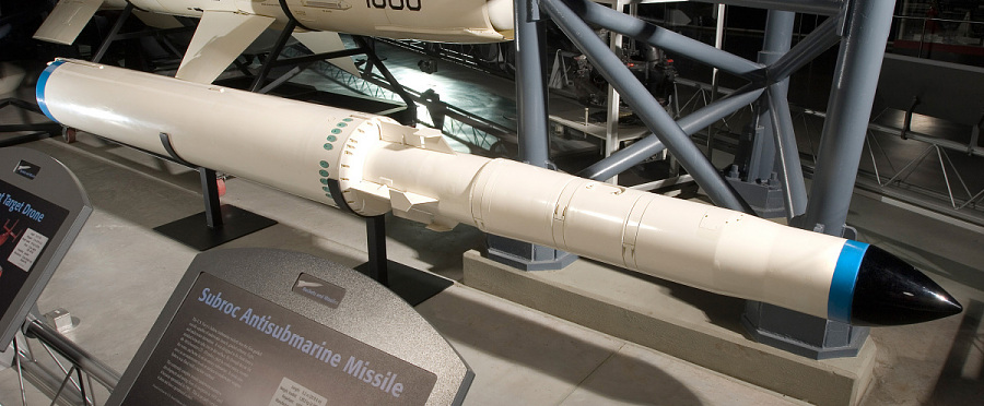
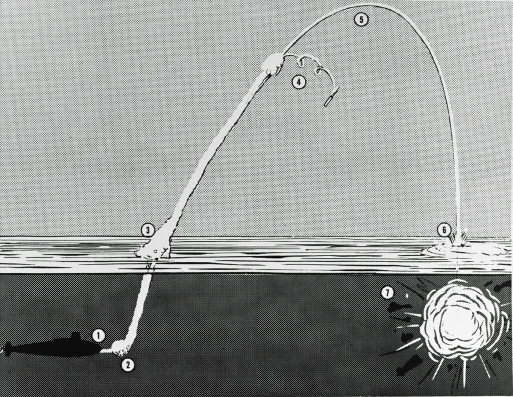
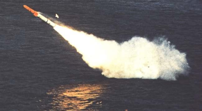
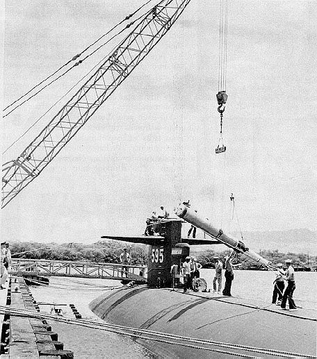
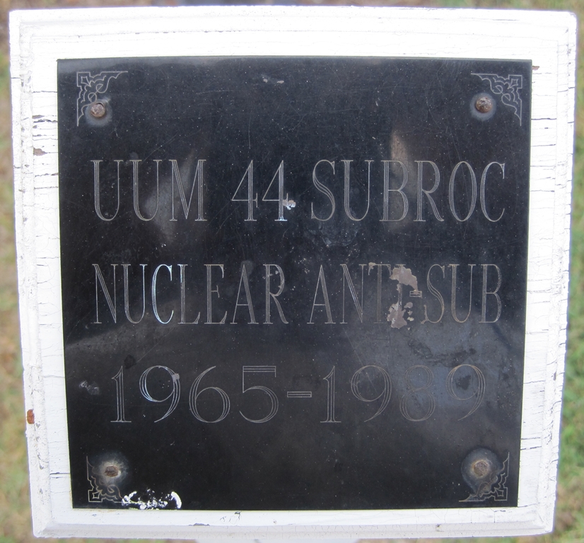
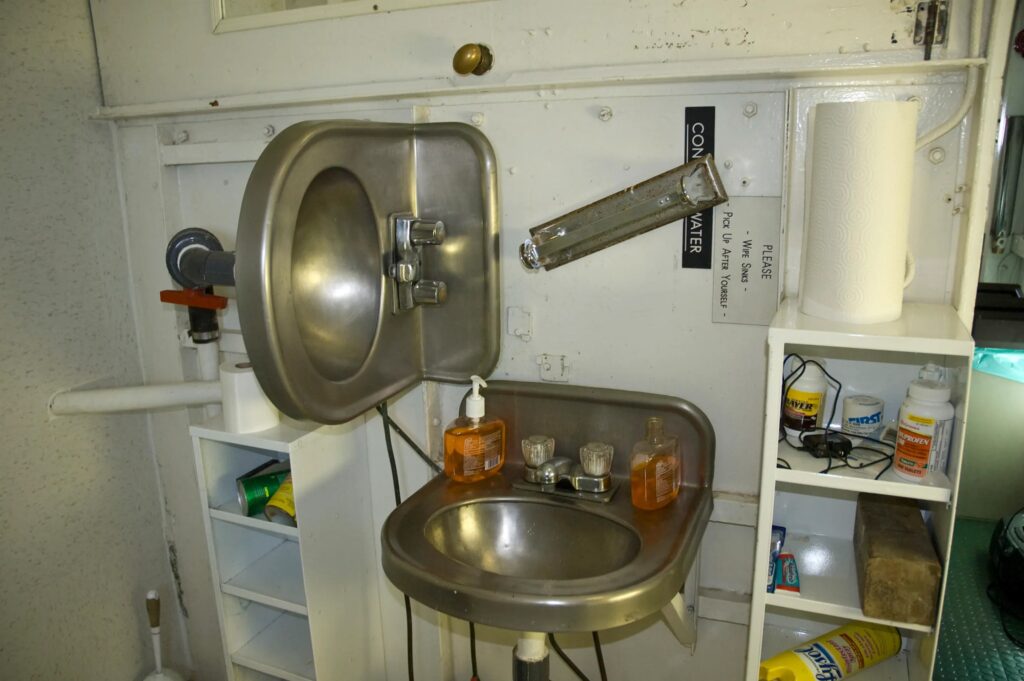
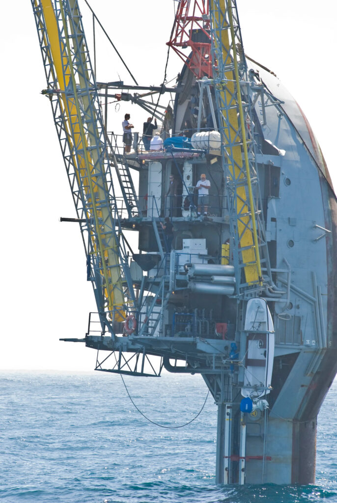
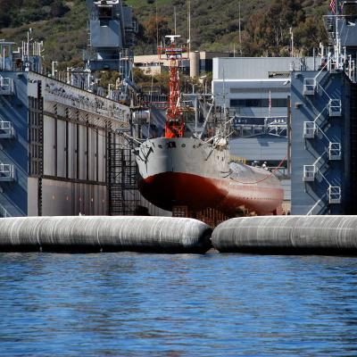
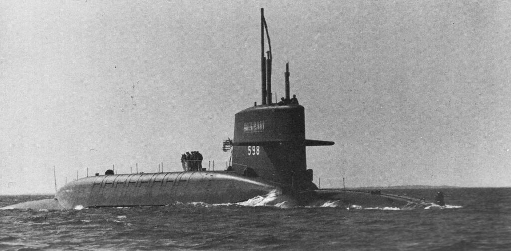
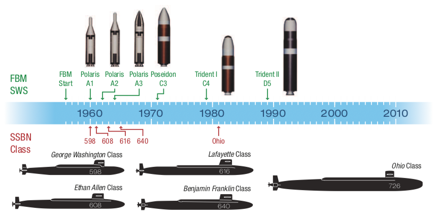
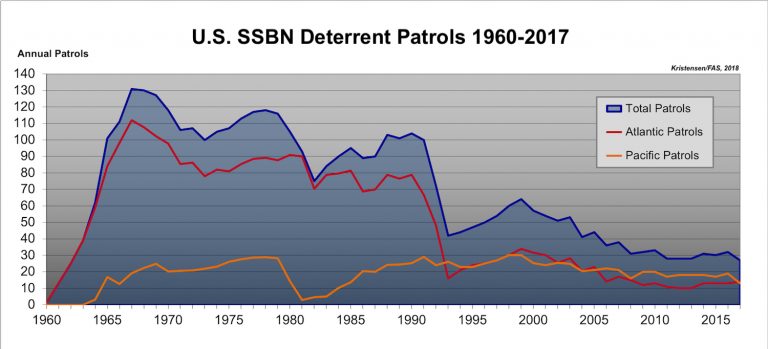
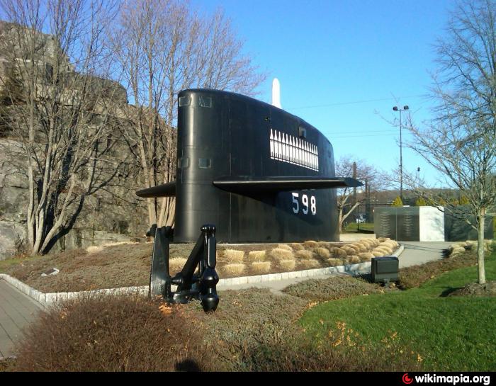
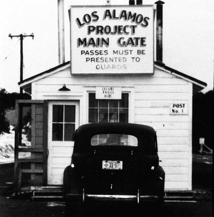
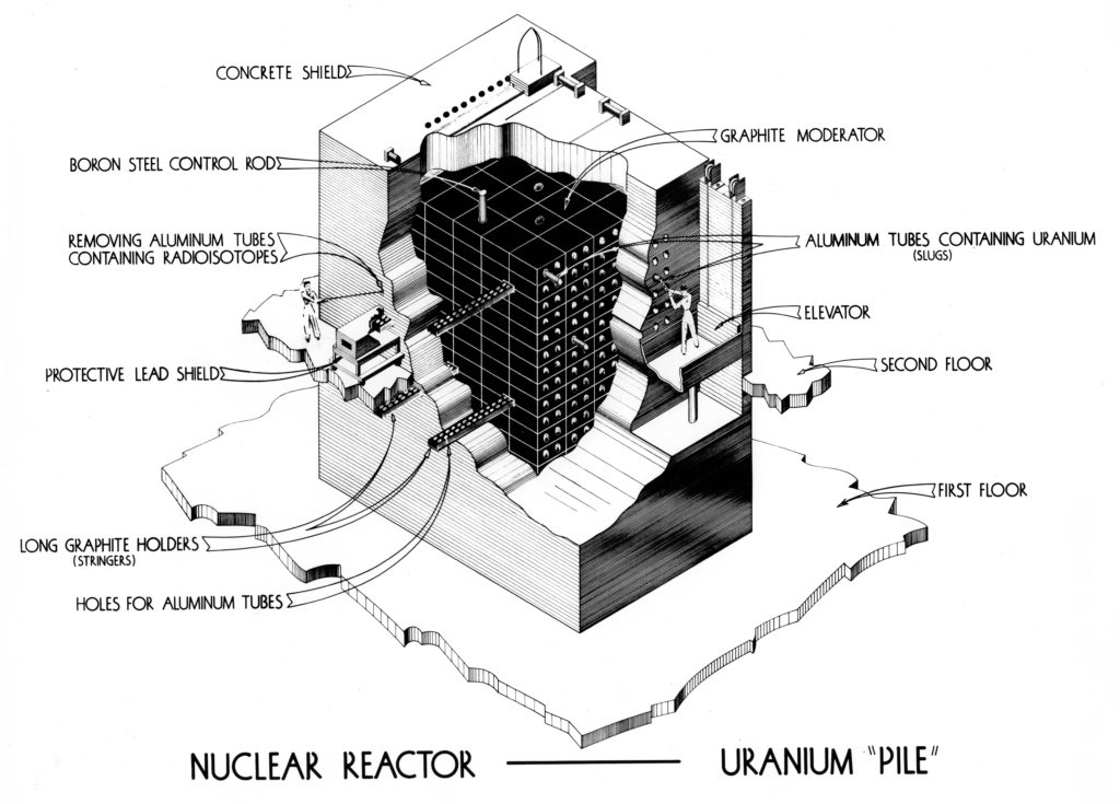
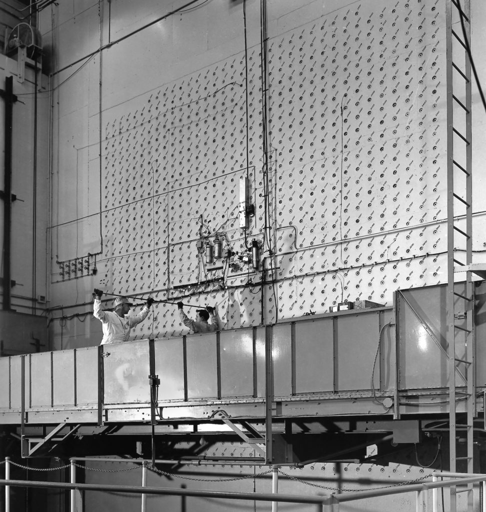
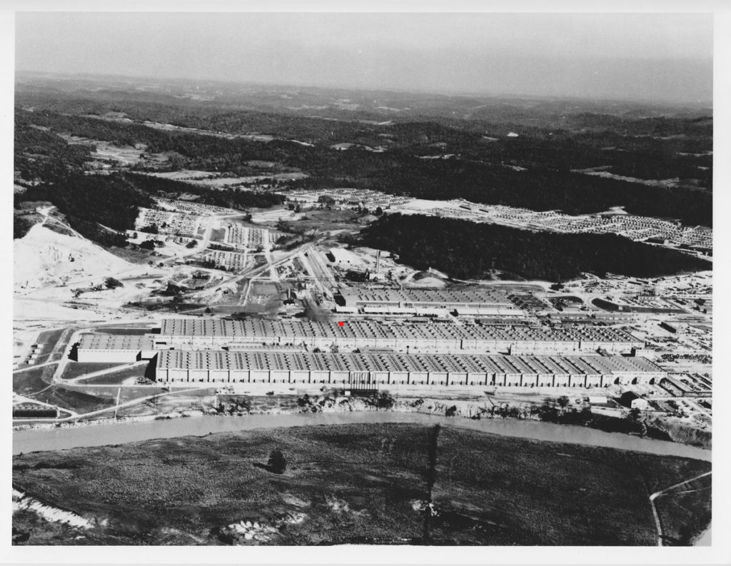
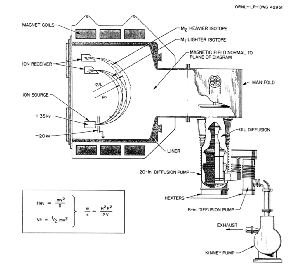
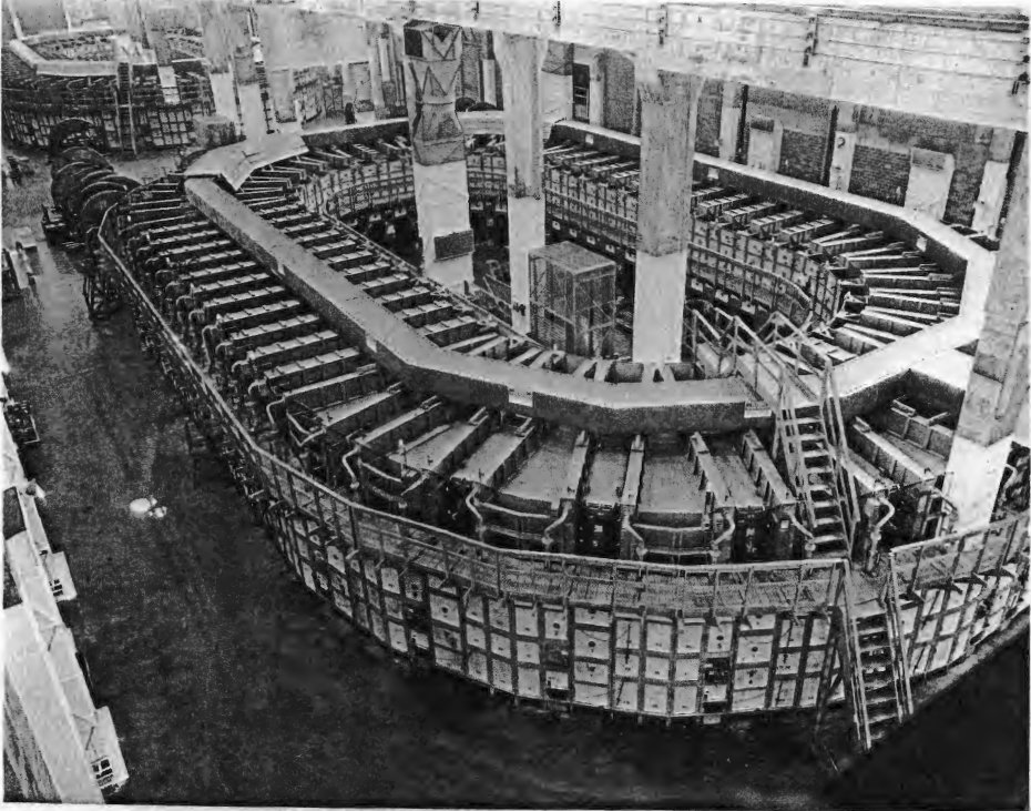
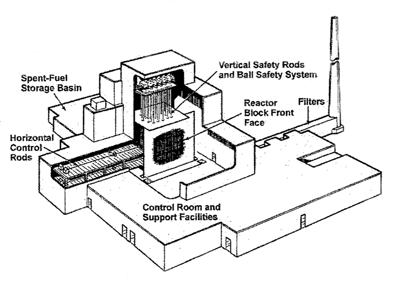
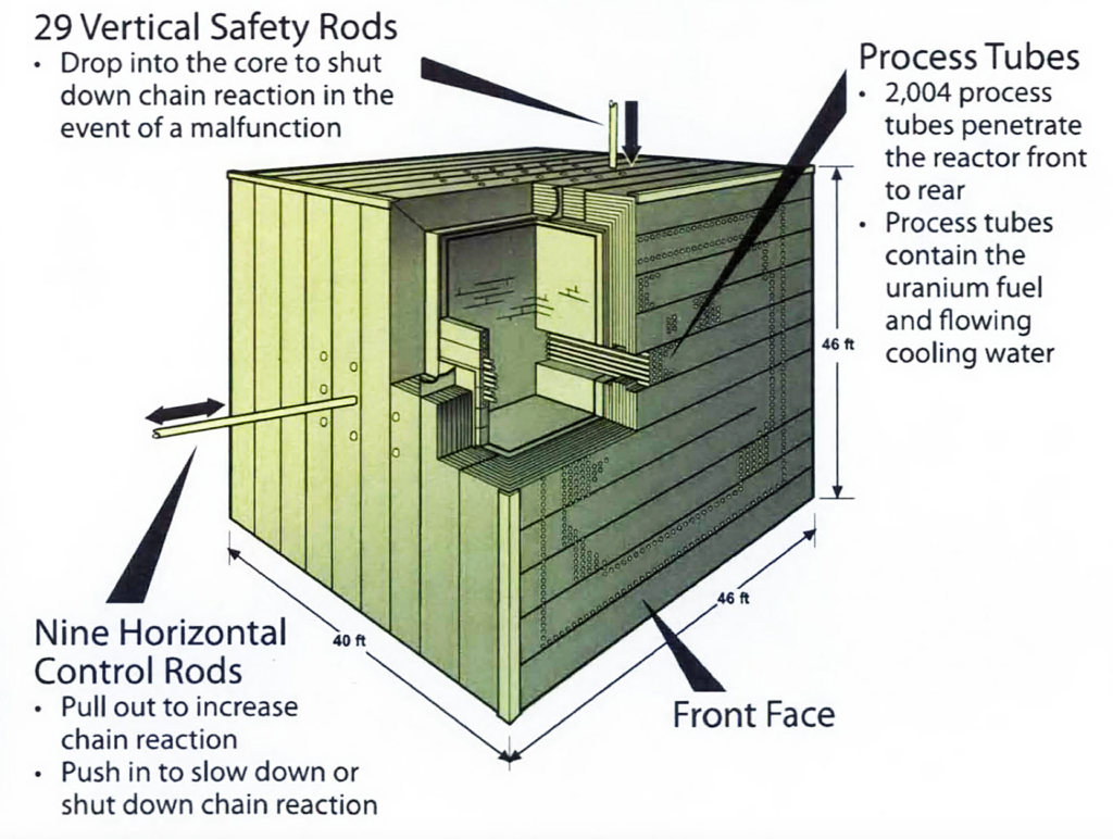
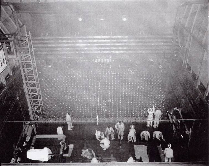
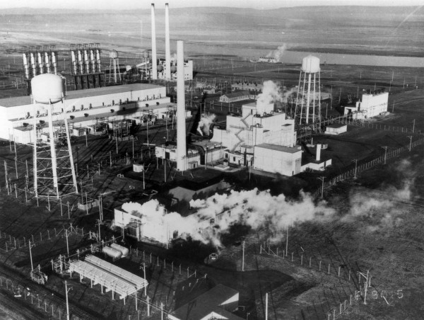
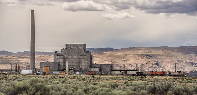
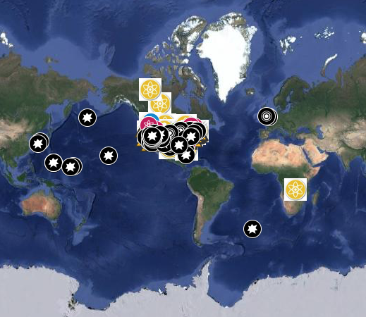


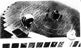
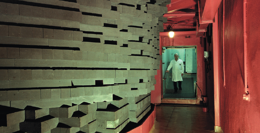
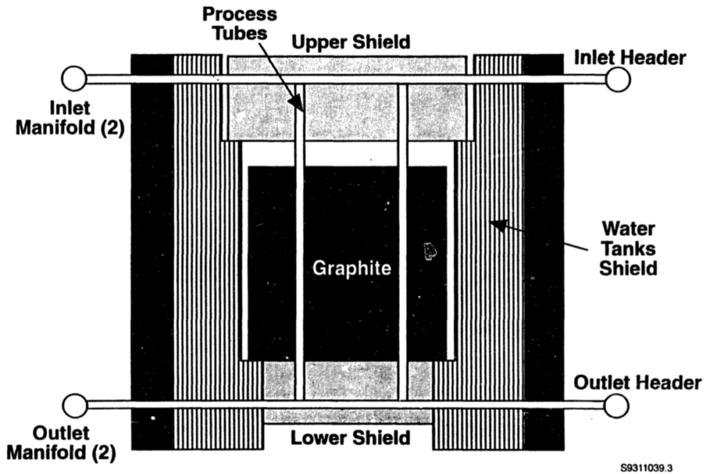
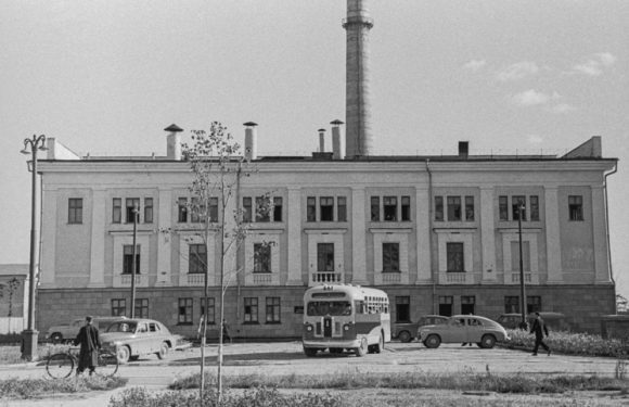
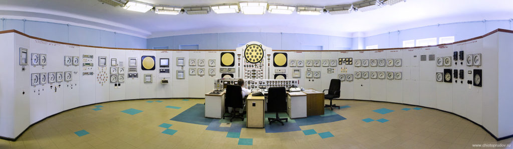
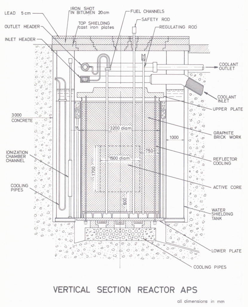
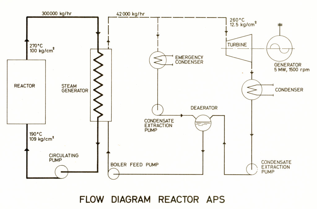
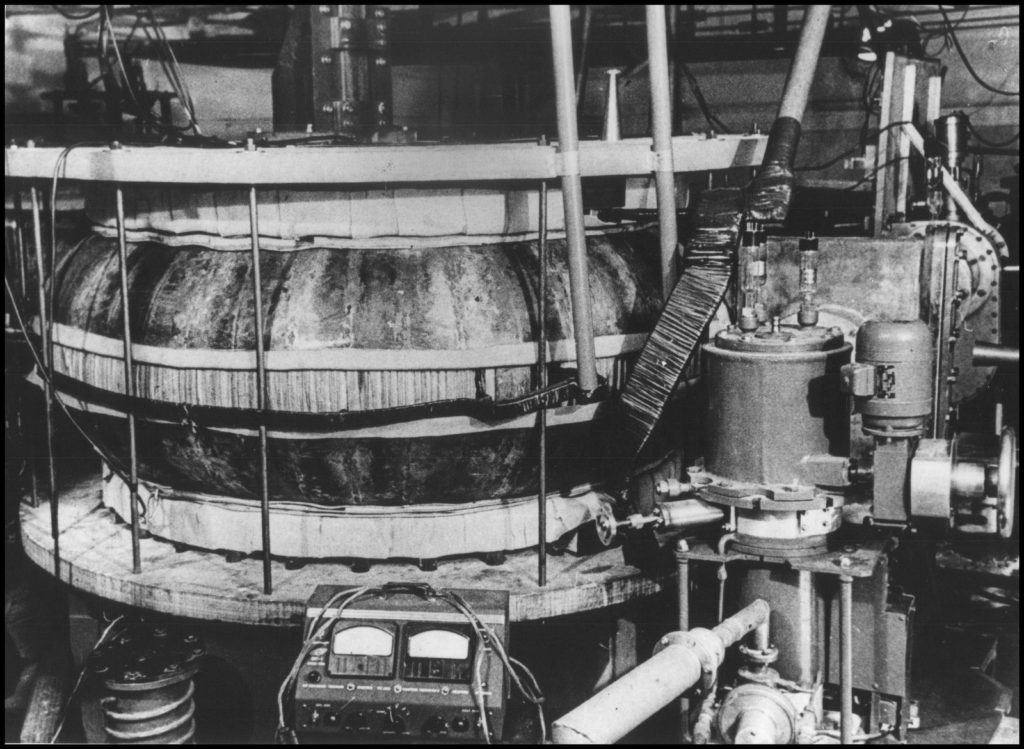
 Summit supercomputer. Source: NVIDIA
 Sierra supercomputer. Source: Lawrence Livermore National Laboratory / Randy Wong
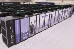 Source: LANL
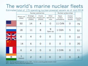 Source: two charts by author


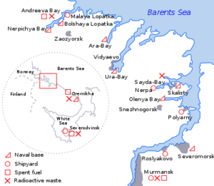


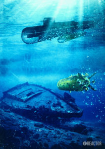


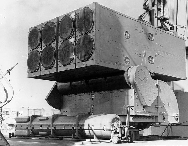
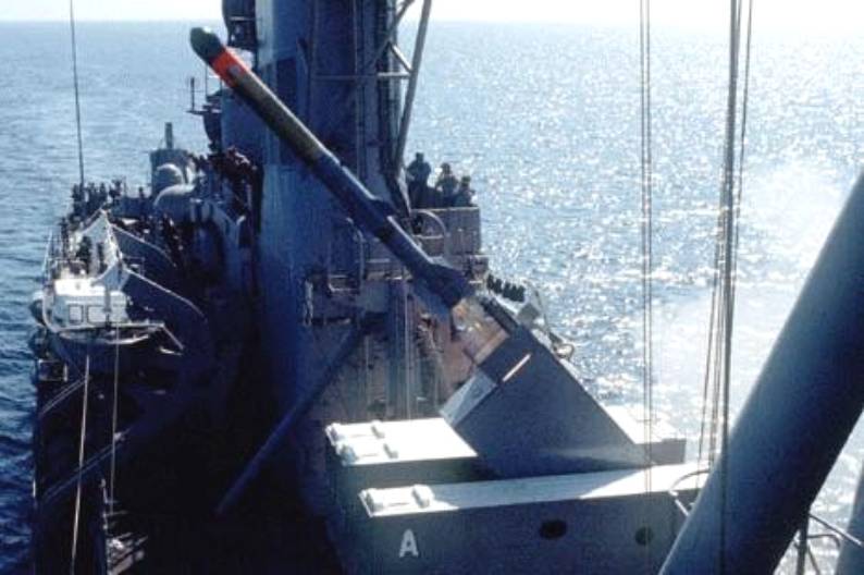
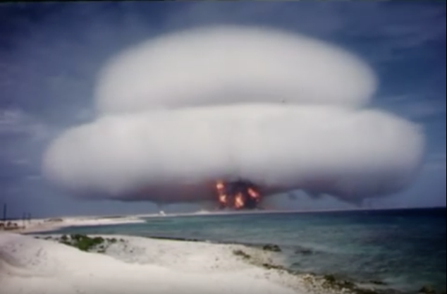


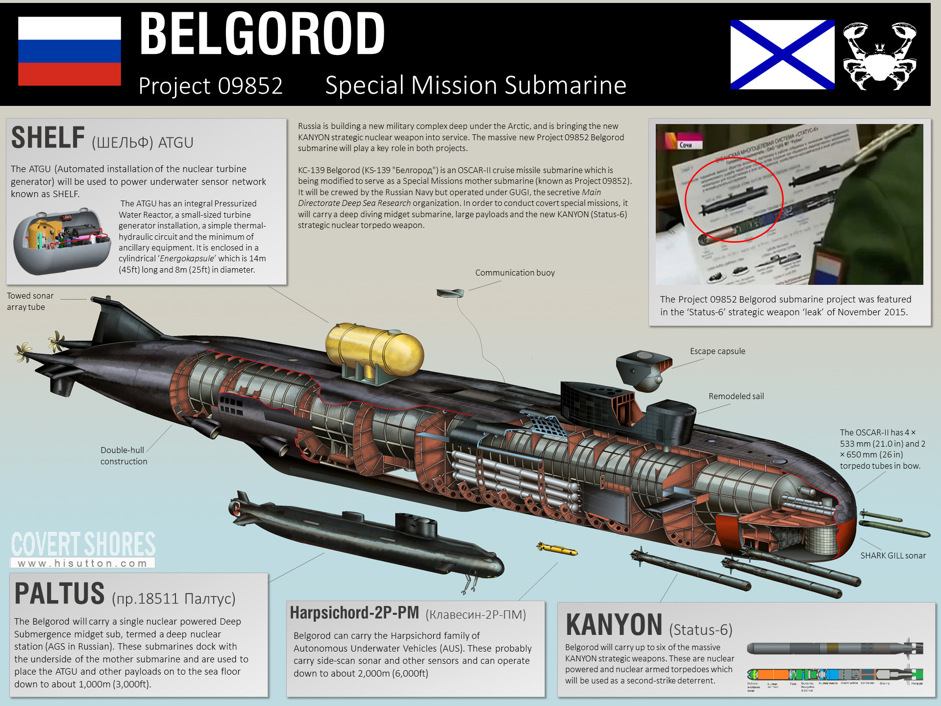