Tag Archives: National Aeronautics and Space Administration

Webb Space Telescope Provides an Extraordinary View of the Planet Neptune

Peter Lobner

In April 2021, I posted a short article entitled, “Multi-messenger Astronomy Provides Extraordinary Views of Uranus,” which included two composite views of Uranus, created by combining near-infrared images taken by the Keck-1 telescope at an elevation of 4,145 meters (13,599 ft) on Maunakea, Hawaii, with X-ray images taken with the Advanced CCD Imaging Spectrometer (ACIS) aboard the orbiting Chandra X-Ray Observatory.

Now, the Webb Space Telescope has taken stunning near-infrared images of the next, and outermost, planet in our solar system, Neptune (sorry, Pluto). You can read NASA’s 21 September 2022 news release on these images here: https://www.nasa.gov/feature/goddard/2022/new-webb-image-captures-clearest-view-of-neptune-s-rings-in-decades

The Webb images of Neptune, taken on July 12, 2022, are reproduced below.

NASA: “Webb captured seven of Neptune’s 14 known moons: Galatea, Naiad, Thalassa, Despina, Proteus, Larissa, and Triton. Neptune’s large and unusual moon, Triton, dominates this Webb portrait of Neptune as a very bright point of light sporting the signature diffraction spikes seen in many of Webb’s images.”
Source: NASA, ESA, CSA, STScI
NASA: “…image of Neptune……brings the planet’s rings into full focus for the first time in more than three decades. The most prominent features of Neptune’s atmosphere in this image are a series of bright patches in the planet’s southern hemisphere that represent high-altitude methane-ice clouds. More subtly, a thin line of brightness circling the planet’s equator could be a visual signature of global atmospheric circulation that powers Neptune’s winds and storms. Additionally, for the first time, Webb has teased out a continuous band of high-latitude clouds surrounding a previously-known vortex at Neptune’s southern pole.” Source: NASA, ESA, CSA, STScI

The Space Telescope Science Institute (STScI) has created a Resource Gallery of Webb Space Telescope images, which you can browse here: https://webbtelescope.org/resource-gallery/images. Currently there are 280 images in the Webb Resource Gallery.  I think this is a website worth revisiting from time to time.

NASA’s Solar System Exploration website provides views of Neptune from several earlier sources, including the 1989 Voyager 2 deep space probe, the Hubble Space Telescope and the European Southern Observatory’s (ESO) Very Large Telescope (VLT). Check it out here: https://solarsystem.nasa.gov/planets/neptune/galleries/

2018: The following image was taken in July 2018 during the testing of the narrow-field, adaptive optics mode of the optical/infrared MUSE/GALACSI instrument on ESO’s VLT, which is located at an elevation of 2,635 m (8,645 ft) at Cerro Paranal, in the Atacama Desert of northern Chile.

2018 VLT image of Neptune. The corrected image is sharper than a comparable image from the NASA/ESA Hubble Space Telescope. Source: ESO/P. Weilbacher (AIP)

1994: The more recent Webb Space Telescope and VLT images are much better than the Hubble Space Telescope optical-range images of Neptune taken more than two decades earlier, in 1994.

NASA: “The images were taken in 1994 on October 10 (upper left), October 18 (upper right), and November 2 (lower center). Hubble is allowing astronomers to study Neptune’s dynamic atmosphere with a level of detail not possible since the 1989 flyby of the Voyager 2 space probe. Building on Voyager’s initial discoveries, Hubble is revealing that Neptune has a remarkably dynamic atmosphere that changes over just a few days. The temperature difference between Neptune’s strong internal heat source and its frigid cloud tops (-260 degrees Fahrenheit) might trigger instabilities in the atmosphere that drive these large-scale weather changes. In addition to hydrogen and helium, the main constituents, Neptune’s atmosphere is composed of methane and hydrocarbons, like ethane and acetylene.” Source: NASA, JPL, STScI

1989: In October 1989, the following whole planet view of Neptune was produced using images taken through the green and orange filters on the narrow angle camera during the Voyager 2 spacecraft flyby of the planet.

NASA: “This picture of Neptune was taken by Voyager 2 less than five days before the probe’s closest approach of the planet on Aug. 25, 1989. The picture shows the “Great Dark Spot” — a storm in Neptune’s atmosphere — and the bright, light-blue smudge of clouds that accompanies the storm”. 
Source: NASA/JPL-Caltech (1989)
 

In the future, we can hopefully look forward to more detailed multi-messenger images of Neptune, combining the near-infrared images from Webb with images from other observatories that can view the planet in different spectral bands.

For more information

Video

Multi-messenger Astronomy Provides Extraordinary Views of Uranus

Peter Lobner, updated 19 December 2023

1. Introduction

Uranus, the seventh planet from the Sun, is an ice giant planet with 27 known moons in a unique orbit beyond Saturn. Uranus makes a complete orbit around the Sun in about 84 Earth years. It is the only planet whose equator is tilted nearly at a right angle to its orbital plane, which results in the polar regions pointing toward the Sun (and Earth) during parts of the orbit.

Uranus was visited briefly by NASA’s Voyager 2 spacecraft during its January 1986 flyby, which came within 81,500 km (50,600 miles) of the planet’s cloud tops. Since then, Uranus has been studied at visible, near-infrared and X-ray wavelengths from the perspective of terrestrial and near-Earth, space-based observatories.

Visible light has a wavelength in the range from about 350 to 750 nanometers (nm, 10-9meters) or 3,500 to 7,500 Angstroms.  Near-infrared light is the part of the infrared spectrum that is closest to the visible light spectrum, but at a longer wavelength, from about 800 to 2,500 nm.  X-rays have a much shorter wavelength, from about 20 to 0.001 nm.  In the following chart, you can see the relative placement of visible and near-infrared light and X-rays in the electromagnetic spectrum.

Electromagnetic spectrum. Source: Wikipedia

2. 2021 composite images of Uranus at visible / near-infrared and X-ray wavelengths

In March 2021, the National Aeronautics and Space Administration (NASA) announced that its orbiting Chandra X-ray Observatory had made the first ever detection of X-rays coming from the ice giant planet Uranus.  Recent analysis of Chandra observations from 2002 and 2017 resulted in this discovery. You can read NASA’s 2021 announcement of this discovery here: https://chandra.si.edu/photo/2021/uranus/

X-rays coming from other planets have been detected in the past.  NASA reported, “Like Jupiter and Saturn, Uranus and its rings appear to mainly produce X-rays by scattering solar X-rays, but some may also come from auroras…… The X-rays from auroras on Jupiter come from two sources: electrons traveling down magnetic field lines, as on Earth, and positively charged atoms and molecules raining down at Jupiter’s polar regions. However, scientists are less certain about what causes auroras on Uranus.”  

Another possible X-ray source could be from an interaction between Uranus’ rings and the near-space charged particle environment around the planet.  This phenomenon has been observed at Saturn.

In connection with the discovery of X-rays coming from Uranus, NASA released two spectacular composite (multi-messenger) images of the planet created by combining images from two different parts of the electromagnetic spectrum: optical / near-infrared and X-ray. 

The components of the first composite image are described below:

  • Near-infrared image: This was taken in July 2004 with the 10-meter (32-foot 10-inch) Keck-1 telescope located at an altitude of 4,145 meters (13,599 ft) on Maunakea, Hawaii.
  • The X-ray image: This was produced with 7 August 2002 data from the Advanced CCD Imaging Spectrometer (ACIS) aboard Chandra, which has a spatial resolution of 0.5” (seconds). The angular size of Uranus for the observation was 3.7”. The X-rays were in the 0.6 to 1.1 keV (2.1 to 1.1 nm) spectral range, which is consistent with X-ray emissions from Jupiter and Saturn. 
(Left) Keck-1 July 2004 near-infrared image of Uranus. The North Pole is at the 4 o’clock position. Sources: Space Science Institute;  University of Wisconsin-Madison / W. M. Keck Observatory (Right) Chandra August 2002 ACIS X-ray image of Uranus.  Sources: NASA/CXO/University College London
2021 Keck-1 & Chandra ACIS composite image

The second 2021 composite image, shown below, was created from a Keck optical image and X-ray images made with Chandra’s High Resolution Camera (HRC) during observations on 11 and 12 November 2017.  The HRC is sensitive to softer X-ray emissions (down to 0.06 keV, 20.7 nm) than ACIS, enabling it to collect more photons in the 0.1–1.2 keV (12.4 to 0.1 nm) range most important for planetary studies. The authors report, ”These fluxes exceed expectations from scattered solar emission alone, suggesting either a larger X-ray albedo than Jupiter/Saturn or the possibility of additional X-ray production processes at Uranus.”

2021 Keck & Chandra HRC composite image
Sources:  X-ray: NASA/CXO/University College London/W. Dunn 
et al; Optical: W.M. Keck Observatory

The authors conclude by noting that, “Further, and longer, observations with Chandra would help to produce a map of X-ray emission across Uranus and to identify, with better signal-to-noise, the source locations for the X-rays, constraining possible contributions from the rings and aurora…… However, the current generation of X-ray observatories does not provide sufficient sensitivity to spectrally characterize the short interval temporal fluctuation observed in the November 12, 2017 observation.”

New space-based X-ray observational capabilities are being developed by NASA and the European Space Agency (ESA), but won’t be operational for a decade or more:

3. 2023 JWST near-infrared images of Uranus

The James Webb Space Telescope (JWST), which has four science instruments designed to observe at optical to mid-infrared (0.6 – 28.3 microns) wavelengths, produced its first images of Uranus in April 2023.

Annotated image of Uranus captured by the JWST on 6 Feb. 2023,  provides a view of the bright North polar ice cap and glowing clouds at near-infrared wavelengths of 1.4 to 3.0 microns. Sources: NASA, ESA, CSA, STScI

Wide field image of Uranus captured by the JWST on 6 Feb. 2023 at near-infrared wavelengths of 1.4 to 5.0 microns. Note  that 14 of the 27 known moons are identified in the image. Also note the many distant galaxies in this image. Sources: NASA, ESA, CSA, STScI

Enlarged view of the 6 Feb. 2023 JWST near-infrared image shows the bright North polar cap, glowing clouds, details of the ring structure and many of the inner moons. Sources: NASA, ESA, CSA, STScI

4. For more information:

The Moon has Never Looked so Colorful

Peter Lobner

On 20 April 2020, the U.S. Geological Survey (USGS) released the first-ever comprehensive digital geologic map of the Moon.  The USGS described this high-resolution map as follows:

“The lunar map, called the ‘Unified Geologic Map of the Moon,’ will serve as the definitive blueprint of the moon’s surface geology for future human missions and will be invaluable for the international scientific community, educators and the public-at-large.”

Color-coded orthographic projections of the “Unified Geologic Map of the Moon” showing the geology of the Moon’s near side (left) and far side (right).  Source:  NASA/GSFC/USGS

You’ll find the USGS announcement here:  https://www.usgs.gov/news/usgs-releases-first-ever-comprehensive-geologic-map-moon

You can view an animated, rotating version of this map here:  https://www.youtube.com/watch?v=f2Nt7DxUV_k

This remarkable mapping product is the culmination of a decades-long project that started with the synthesis of six Apollo-era (late 1960s – 1970s) regional geologic maps that had been individually digitized and released in 2013 but not integrated into a single, consistent lunar map. 

This intermediate mapping product was updated based on data from the following more recent lunar satellite missions:

  • NASA’s Lunar Reconnaissance Orbiter (LRO) mission:
    • The Lunar Reconnaissance Orbiter Camera (LROC) is a system of three cameras that capture high resolution black and white images and moderate resolution multi-spectral images of the lunar surface: http://lroc.sese.asu.edu
    • Topography for the north and south poles was supplemented with Lunar Orbiter Laser Altimeter (LOLA) data: https://lola.gsfc.nasa.gov
  • JAXA’s (Japan Aerospace Exploration Agency) SELENE (SELenological and ENgineering Explorer) mission:

The final product is a seamless, globally consistent map that is available in several formats: geographic information system (GIS) format at 1:5,000,000-scale, PDF format at 1:10,000,000-scale, and jpeg format.

At the following link, you can download a large zip file (310 Mb) that contains a jpeg file (>24 Mb) with a Mercator projection of the lunar surface between 57°N and 57°S latitude, two polar stereographic projections of the polar regions from 55°N and 55°S latitudes to the poles, and a description of the symbols and color coding used in the maps.

https://astrogeology.usgs.gov/search/map/Moon/Geology/Unified_Geologic_Map_of_the_Moon_GIS_v2

These high-resolution maps are great for exploring the lunar surface in detail. A low-resolution copy (not suitable for browsing) is reproduced below.

For more information on the Unified Geologic Map of the Moon, refer to the paper by C. M. Fortezzo, et al., “Release of the digital Unified Global Geologic Map of the Moon at 1:5,000,000-scale,” which is available here:  https://www.hou.usra.edu/meetings/lpsc2020/pdf/2760.pdf

Israel Poised to Become the 4th Nation to Land a Spacecraft on the Moon

Peter Lobner, updated 12 April and 14 May 2019

In my 6 August 2016 post, “Lunar Lander XCHALLENGE and Lunar XPrize are Paving the way for Commercial Lunar Missions,” I reported on the status of the Google Lunar XPrize, which was created in 2007 to “incentivize space entrepreneurs to create a new era of affordable access to the Moon and beyond,” and actually deliver payloads to the Moon.  In addition, the lunar payloads were tasked with moving 500 meters (1,640 feet) after landing and transmitting high-definition photos and video back to Earth. Any additional science data would be a plus.  In January 2018, after concluding that none of the remaining competitors could meet the extended 31 March 2018 deadline for landing on the Moon, the Google Lunar XPrize competition was cancelled, with the $30M in prizes remaining unclaimed. You can read this post here:

https://lynceans.org/all-posts/lunar-lander-xchallenge-and-lunar-xprize-are-paving-the-way-for-commercial-lunar-missions/

One of the competing Lunar XPrize teams was SpaceIL from Israel, which was developing a small lunar spacecraft named Beresheet (originally named Sparrow), that was designed to hitch a ride into an elliptical Earth orbit as a secondary payload on a SpaceX Falcon 9 commercial launch vehicle and then transfer itself to a lunar orbit and finally land on the Moon.  

The SpaceIL lunar landing program continued after cancellation of the Lunar XPrize competition.  You’ll find details on the SpaceIL lunar program here:

http://www.visit.spaceil.com

As completed by SpaceIL and Israel Aerospace Industries (IAI), the Beresheet spacecraft has a launch mass of 600 kg (1,323 pounds) and a landing mass of about 180 kg (397 pounds).  The lander carries imagers, a magnetometer, a laser retro-reflector array (LRA) provided by the U.S. National Aeronautics and Space Administration (NASA), and a time capsule of cultural and historical Israeli artifacts.

The Beresheet spacecraft.  Source:  by Abir Sultan/EPA-EFE

After landing on the Moon, the Beresheet spacecraft electronic systems are expected to remain operational only for a few days. The original Lunar XPrize plan to demonstrate mobility and move the spacecraft after landing on the Moon has been dropped.  The laser retro-reflectors will enable the spacecraft to serve as a fixed geographic reference point on the lunar surface long after the mission ends.While not designed for a long lunar surface mission, Beresheet is intended to demonstrate advances in technology that enable low-cost, privately-funded missions to another body in the solar system.  Beresheet was developed and constructed for about $100 million.  You’ll find more information on the Beresheet spacecraft here:

https://directory.eoportal.org/web/eoportal/satellite-missions/content/-/article/beresheet-lunar-lander

Beresheet was launched from Cape Canaveral, FL on 21 Feb 2019 into an initial elliptical Geosynchronous Transfer Orbit (GTO) that was dictated by the requirements for the Falcon 9 booster’s primary payload. Once in GTO, Beresheet used its small rocket engine to gradually raise its orbit to a 400,000 km (248,548 mile) apogee to intersect the Moon’s circular orbit, and phase its orbit so the spacecraft passed close to the Moon and could maneuver into a transfer orbit and be captured by the Moon’s gravity.  This mission profile is illustrated below.

Source:  SpaceIL

You can watch a short video with an animation of this mission profile here:

On 4 April, SpaceIL tweeted: “Critical lunar orbit capture took place successfully. #Beresheet is now entering an elliptical course around the #moon, as we get closer to the historical landing #11.4″

After circularizing its lunar orbit, Beresheet is scheduled to land on the Moon on 11 April 2019.  NASA is providing communications support during the mission.

Artist’s concept of the Beresheet lander on the lunar surface.  
Source: Israel Aerospace Industries(IAI)

On 28 March, the X Prize founder and Executive Chairman Peter Diamand announced that, if the lunar landing is successful, the Foundation would award a $1 million “Moonshot Award” to Beresheet’s builders. Peter Diamand noted, “SpaceIL’s mission represents the democratization of space exploration.”

Best wishes to the SpaceIL team for a successful lunar landing.  If successful, Israel will become the 4thnation, after Russia (Soviet Union), USA and China to land spacecraft on the Moon.

Update 12 April 2019:  Beresheet spacecraft crashed during Moon landing attempt

The Beresheet spacecraft successfully initiated its descent from lunar orbit on 11 April 2019.  Initial telemetry indicated that the landing profile was proceeding as planned.

Beresheet status graphic during landing sequence.  
Source: IAI / SpaceIL
Photo taken from Beresheet during the descent, from an altitude of about 22 km. Source:  IAI / SpaceIL

Communications with the spacecraft was lost when Beresheet was about 489 feet (149 meters) above the moon’s surface.  Opher Doron, the general manager of IAI, reported during the live broadcast, “We had a failure in the spacecraft; we unfortunately have not managed to land successfully.” 

X Prize founder and Executive Chairman Peter Diamandis announced that SpaceIL and IAI will receive the $1 million Moonshot Award despite failing to make the planned soft landing on the Moon.

Update 14 May 2019:  Preliminary failure analysis

On 17 April 2019, SpaceIL announced that its preliminary failure analysis indicated that a software command uploaded to restart a failed inertial measuring unit (IMU) may have started a sequence of events that ultimately shut down the main engines prematurely during the landing attempt, resulting in the crash of the Beresheet spacecraft.

Morris Kahn, SpaceIL’s primary source of funding, pledged that the team will try again for a Moon landing with a new spacecraft dubbed “Beresheet 2.0,” which will incorporate lessons learned from the first lunar landing attempt.

For more information on the Beresheet mission, see The Planetary Society mission report at the following link:

http://www.planetary.org/explore/space-topics/space-missions/beresheet.html

Reusable Space Launch Vehicles are Becoming a Reality

Peter Lobner

In my 12 April 2016 post, “Landing a Reusable Booster Rocket on a Dime,” I discussed the first successful flights and recoveries of the SpaceX Falcon 9 orbital booster rocket and Blue Origin’s New Shepard suborbital booster rocket. In the past year, both SpaceX and Blue Origin have successfully launched and recovered several rockets. In addition, SpaceX and Blue Origin both have reused one or more booster rockets that were flown on previous missions.

Here’s a quick look at the SpaceX and Blue Origin track records and their future plans for even more ambitious recoverable launch vehicles. We’ll also take a brief look at what competitors are doing with their existing and planned launch vehicles.

SpaceX reusable booster rockets: Falcon 9 v1.2, Falcon Heavy, and Interplanetary Transport System

The Falcon 9 v1.2 is the current, operational version of this commercial, medium-lift, two-stage family of launch vehicles. This booster has a length of 230 ft (70 m) with the payload fairing and a booster diameter of 12 ft (3.66 m). The first stage generates 1.7 million pounds of thrust from seven Merlin engines burning liquid oxygen (LOX) and RP-1 kerosene. The second stage uses a single Merlin engine optimized for vacuum conditions. The Falcon 9 v1.2 specified payload mass is:

  • 50,265 pounds (22.8 metric tons, 22,800 kg) to Low Earth Orbit (LEO),
  • 18,298 pounds (8.3 metric tons, 8,300 kg) to Geosynchronous Transfer Orbit (GTO), or
  • 8,862 pounds (4.02 metric tons, 4,020 kg) to escape velocity.

Falcon Heavy is an advanced heavy-lift, two-stage launch vehicle with a first stage comprised of three Falcon 9 booster rockets. The first stage generates 5.1 million pounds of thrust from 21 Merlin engines. The Falcon Heavy specified payload mass is:

  • 119,931 pounds (54.4 metric tons, 54,400 kg) to LEO,
  • 48,942 pounds (22.2 metric tons, 22,200 kg) to GTO, or
  • 29,983 pounds (13.6 metric tons, 13,600) kg to escape velocity.

The first Falcon Heavy is expected to be launched in late 2017.

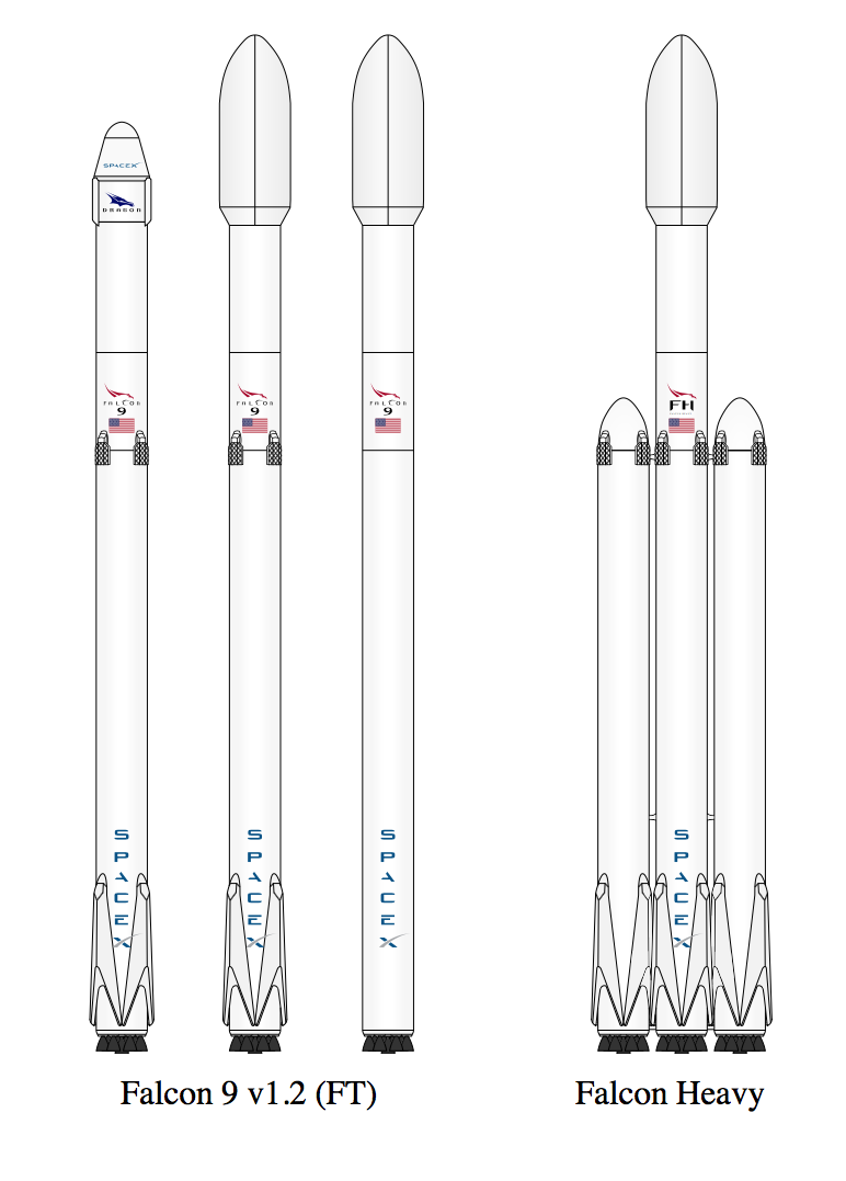
The Falcon 9 v1.2 family and the Falcon Heavy launch vehicles are shown in the following diagram. The scale-up from Falcon 9 V1.2 to Falcon Heavy is relatively straightforward. Versions designed for recovering the first stage include four extendable landing legs near the base of the rocket. In the diagram below, you can see that one version of the Falcon 9 does not include the landing legs, sacrificing booster recovery for greater booster performance.
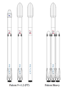
  Source: SpaceX   

SpaceX describes their Falcon 9 booster recovery process as follows:

“After being jettisoned, the first stage (autonomously) initiates a flip maneuver and begins a powered return back to Earth. Using a combination of reaction control thrusters, forward-mounted grid fins, and thrust from one to three of the main engines, the first stage flies either to a remotely-operated ship in the Atlantic (or Pacific) Ocean, or to land. Upon arrival, the vehicle deploys a set of landing legs and sets itself down upright.”

In practice, SpaceX expects to recover about 1/3 of its boosters on land, back near the launch site. Boosters for most of the remaining missions (primarily the higher-energy missions) will be recovered on a downrange drone ship. You can watch a short video explaining these two mission profiles at the following link:

https://www.youtube.com/watch?v=lEr9cPpuAx8

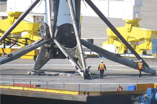
A recovered Falcon 9 first stage booster rocket is very large:

  • overall length of about 151 ft (46 m) in landing configuration,
  • dry mass is about 50,706 pounds (23,000 kg), and
  • estimated total mass is 94,578 pounds (42,900 kg) with 5% residual fuel after landing.

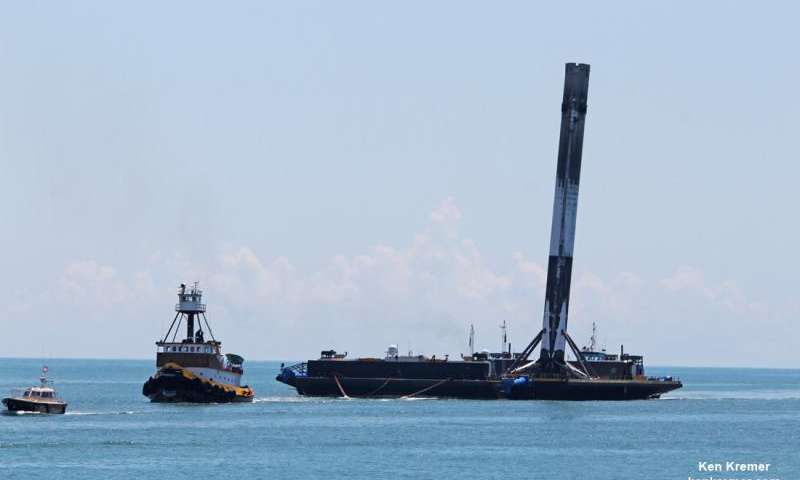
The large scale of the Falcon 9 booster is apparent in the following photo taken after a landing on the stationary drone ship.
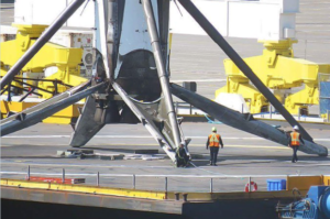
Source: SpaceX
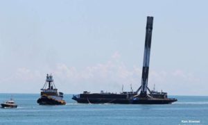
Source: Ken Kremer/kenkremer.com

You can see a video of the January 2017 Falcon 9 v1.2 launch and booster recovery at the following link:

https://www.youtube.com/watch?v=c8wy5sQ2JDE

The SpaceX mission on 30 March 2017 marked two important milestones:

  • The first reuse of a Falcon 9 booster stage, which was recovered on the drone barge and will be available again for reuse.
  • The first recovery of the costly (about $6 million) payload fairing, which was jettisoned during ascent and returned under parachute for an ocean splashdown.  The payload fairing will be reused.

As of 3 April 2017, the SpaceX Falcon 9 scorecard is:

  • Thirteen booster recoveries attempted
  • Three successful recoveries on land; first in December 2015
  • Six successful recoveries on a drone ship at sea, first in April 2016
  • Four drone ship recovery failures
  • One booster stage reused

The number of times a Falcon 9 first stage can be re-flown is not clearly specified. However, Elon Musk placed that number at 10 – 20 additional missions, and, with minor refurbishment, up to 100 missions.

Falcon Heavy missions will involve considerably more complex, simultaneous, autonomous booster recovery operations. The port and starboard Falcon 9 boosters will separate first and fly to designated recovery points, likely on land. The core booster will burn longer before separating from the second stage, which will take the payload into orbit. After separation, the core Falcon 9 booster also will fly to a designated recovery point, likely on a downrange drone ship. After a Falcon Heavy launch, it literally will be raining Falcon 9 boosters. This will be a spectacular demonstration of autonomous flight control and range safety.

You’ll find a list of Falcon 9 and Falcon Heavy launches, booster recovery status, and future missions at the following link:

https://en.wikipedia.org/wiki/List_of_Falcon_9_and_Falcon_Heavy_launches

SpaceX has been developing the recoverable Dragon space capsule as a family of spacecraft to be launched by the Falcon booster to conduct a variety of orbital and interplanetary missions. Like the recoverable Falcon booster, the Dragon capsule uses aerodynamic forces to slow its descent into the atmosphere and rocket propulsion for the final landing phase.

  • Dragon CRS: Since October 2012, this unmanned cargo version of the Dragon space capsule has been conducting Commercial Resupply Service (CRS) missions to the International Space Station (ISS) and returning cargo to Earth.
  • Dragon CRS “free-flyer”: The Dragon capsule also can operate independently in Earth orbit carrying a variety of payloads and returning them to Earth.
  • Dragon 2: This is a human-rated version of the Dragon space capsule. The first manned orbital flight in expected 2018.
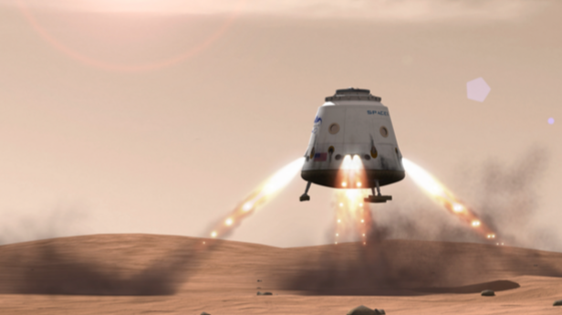
  • Red Dragon: This is an unmanned version of Dragon 2 adapted for a mission to Mars and launched by a Falcon Heavy. Red Dragon is designed to make a propulsive landing on Mars’ surface with a 2,200 pound (1,000 kg) payload. The first launch of a Red Dragon mission could occur as early as 2018. Thereafter, SpaceX plans to conduct “regular “ (as suitable launch windows occur) Red Dragon missions to Mars.

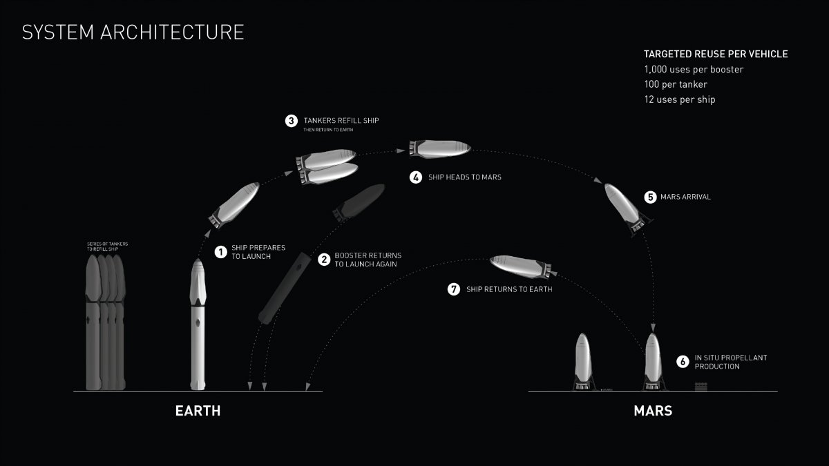
The SpaceX Interplanetary Transport System (ITS) is a concept for an enormous launch vehicle, a manned interplanetary spacecraft, and a tanker spacecraft for refueling the interplanetary spacecraft in Earth orbit before starting the interplanetary phase of the mission. ITS will enable transportation of a large crew and equipment to Mars starting in the late 2020s. Later, when propellant plants have been established on distant bodies in the solar system, the ITS interplanetary spacecraft will be able to refuel in deep space and journey beyond Mars. The ITS is “conceptualized to be fully reusable with 1,000 uses per booster, 100 uses per tanker and 12 round trips to Mars with one spacecraft over a period of over 25 years.”

As shown in the following diagram, the ITS booster rocket carrying the interplanetary spacecraft is much larger than the National Aeronautics and Space Administration’s (NASA) Saturn V used in the 1960s and 1970s on the Apollo lunar missions. At launch, the ITS will be 400 ft (122 m) tall and 39.4 ft (12 m) in diameter.

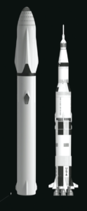
  ITS & Saturn V. Source: SpaceX

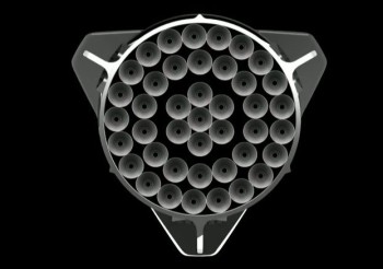
 With 42 Raptor sub-cooled liquid methane / liquid oxygen engines, the first stage will have a liftoff thrust of about 26 million pounds, which is more than three times the thrust of Saturn V. This engine configuration is reminiscent of the Soviet N-1 moon rocket, (circa late 1960s), which clustered 30 engines in a similar configuration.

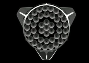
  ITS 1st stage Raptor engines. Source: SpaceX

The ITS specified payload mass is:

  • 1 million pounds (500 metric tons, 500,000 kg) to LEO with a fully expendable booster, or
  • 661,000 pounds (300 metric tons, 300,000 kg) to LEO with a reusable booster

ITS can lift ten times the payload of the Falcon Heavy booster.

The first stage of the ITS launch vehicle will be designed to fly back to the launch site for rapid servicing and reuse (i.e., to launch the refueling tanker spacecraft). In landing configuration, the ITS booster stage will be about 254 ft (77.5 m) long with a dry mass of about 275 tons (25 metric tons, 250,000 kg).

You can watch Elon Musk’s briefing on the ITS concept, including a short video of the ITS launch and interplanetary mission profile, at the following link.

http://www.spacex.com/mars

Can you spell A M B I T I O U S? The SpaceX ITS concept certainly is ambitious, but it offers a much more compelling vision of future manned spaceflight than anything NASA has offered over the past decade.

Blue Origin reusable booster rockets: New Shepard and New Glenn

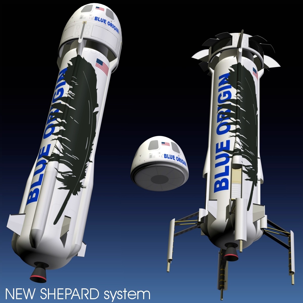
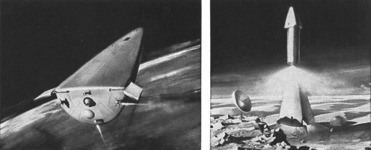
New Shepard is a small, single stage, suborbital rocket intended for research and commercial passenger service to the fringe of space, above the Karman line at 62 miles (330,000 ft, 100 km) above the Earth. New Shepard is named for Project Mercury astronaut Alan Shepard, who, on 5 May 1961, made the first U.S. suborbital flight in the Freedom 7 capsule launched from Cape Canaveral by a Redstone rocket. The New Shepard, in launch and recovery configurations, is shown in the following figure.

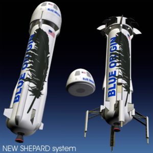
Source: https://www.stlfinder.com/3dmodels/Besos

You can see a short video showing the June 2016 fourth launch and recovery of the New Shepard booster and capsule at the following link:

https://www.youtube.com/watch?v=nNRs2gMyLLk

As of 3 April 2017, the New Shepard scorecard is:

  • Six booster recoveries attempted
  • Five successful recoveries on land; first in November 2015
  • One booster recovery failure
  • One booster stage recovered and used five times

In all of these New Shepard unmanned test flights, the passenger capsule was recovered.

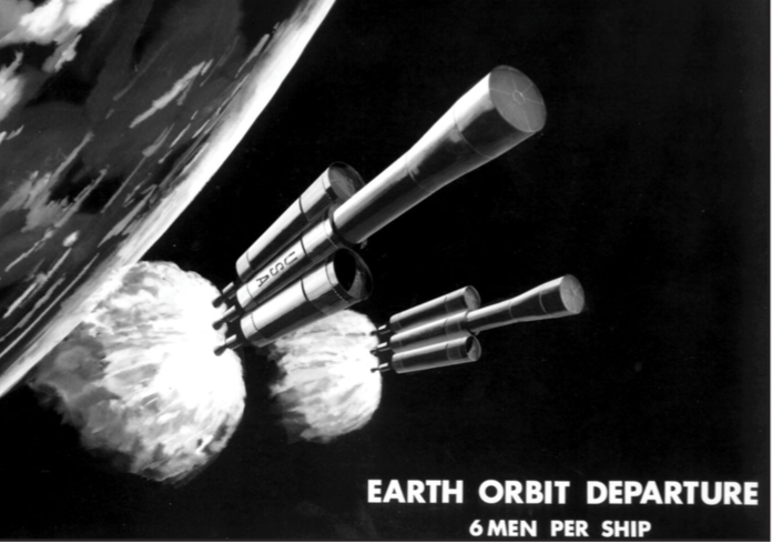
Blue Origin expects to conduct the first manned tests of New Shepard in late 2017. Commercial passenger flights, with up to six people in the space capsule, could begin in 2018.  Blue Origin has stated that they may be able to conduct as many as 50 New Shepard flights per year.

You’ll find a list of New Shepard launches and booster recovery status, at the following link:

https://en.wikipedia.org/wiki/Blue_Origin

On 29 March 2017, the National Aeronautic Association (NAA) announced that it selected Blue Origin New Shepard to receive the prestigious 2016 Robert J. Collier Trophy. The award reads:

“… for successfully demonstrating rocket booster reusability with the New Shepard human spaceflight vehicle through five successful test flights of a single booster and engine, all of which performed powered vertical landings on Earth.”

You can read the complete NAA press release at the following link:

https://naa.aero/userfiles/files/documents/Press%20Releases/Collier%20Trophy%202016.pdf

On 12 September 2016, Jeff Bezos announced Blue Origin’s plans to develop New Glenn, which is a very large, heavy-lift, 2- or 3-stage reusable launch vehicle. New Glenn is named for Project Mercury astronaut John Glenn, who, on 20 February 1962, became the first U.S. astronaut to reach orbit. John Glenn flew in the Friendship 7 capsule launched from Cape Canaveral by an Atlas rocket.

The size of New Glenn is apparent n the following diagram. The two-stage version will be 270 ft (82 m) tall, and the three-stage version will be 313 ft (95 m) tall, approaching the size of NASA’s Saturn V.

Source: Blue Origin

 The New Glenn first stage is powered by seven BE-4 methane / LOX engines rated at a combined 3.85 million pounds of thrust (about ½ of the Saturn V), the second stage is powered by a single BE-4 engine optimized for vacuum conditions and rated at 550,000 pounds of thrust, and the third stage is powered by one BE-3 liquid hydrogen / LOX engine rated at 110,000 pounds thrust. The BE-4 engines in the reusable first stage are designed with a 100-flight lifetime.

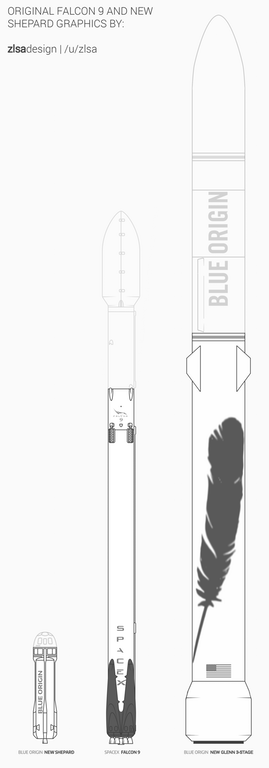
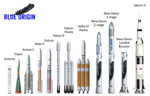
A more detailed size comparison between New Shepard, Falcon 9 and New Glenn is shown in the following diagram.

  Source: zisadesign I /u/zisa

The scale-up from New Shepard, which is not yet operational, to New Glenn is tremendous. The specified payload mass for the two-stage version of New Glenn is:

  • 99,000 pounds (45 metric tons, 45,000 kg) to LEO,
  • 29,000 pounds (13 metric tons, 13,000 kg) to GTO

The three-stage New Glenn will carry heavier payloads.

The first stage of the New Glenn booster is being designed to fly to a designated landing site to be recovered. Aerodynamic surfaces on the first stage will give New Glenn more aerodynamic maneuvering capability than the SpaceX Falcon during the descent to landing. On 7 March 2017, Jeff Bezos gave the following details on the recovery of the first stage.

“Those aerodynamic surfaces allow us to operate with very high availability in very high wind conditions……..We don’t want to constrain the availability of launch based on the availability of the landing of the reusable booster. We put a lot of effort into letting the vehicle fly back with aerodynamic surface control instead of with propulsion.”

Of course, rocket propulsion is needed for the final phase of landing on a large, moving platform at sea. The first stage has six extendable landing legs, and can land safely if only five deploy.

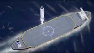
New Glenn landing. Source: Blue Origin

You’ll find a short animated video showing the launch and recovery process for New Glenn at the following link:

https://www.blueorigin.com/#youtubeBTEhohh6eYk

New Glenn flights are expected to start in 2020, about three years after the first SpaceX Falcon Heavy flight.

What are other launch vehicle competitors doing?

No other operational or planned launch vehicles offer the extent of reusability found in the SpaceX Falcon and ITS and the Blue Origin New Shepard and New Glenn. The following launch vehicles will offer only partial reusability.

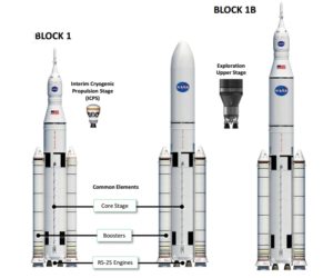
NASA: partially-reusable Space Launch System (SLS)

 NASA is developing the SLS to launch heavy payloads into Earth orbit and to launch the Orion manned spacecraft on a variety of near-Earth and deep space missions. As shown in the following diagram,  the SLS booster rocket has a large, liquid-fueled, two-stage core flanked by two large solid rocket boosters manufactured by Orbital ATK.

SLS is designed to put 150,000 to 290,000 pounds (70,000 to 130,000 kg) into LEO.

SLS launch vehicle: Source: NASA

As with the NASA Space Shuttle, the solid rocket boosters are designed to be recovered and reused. However, the liquid-fueled first stage booster is expendable; not designed for reuse.

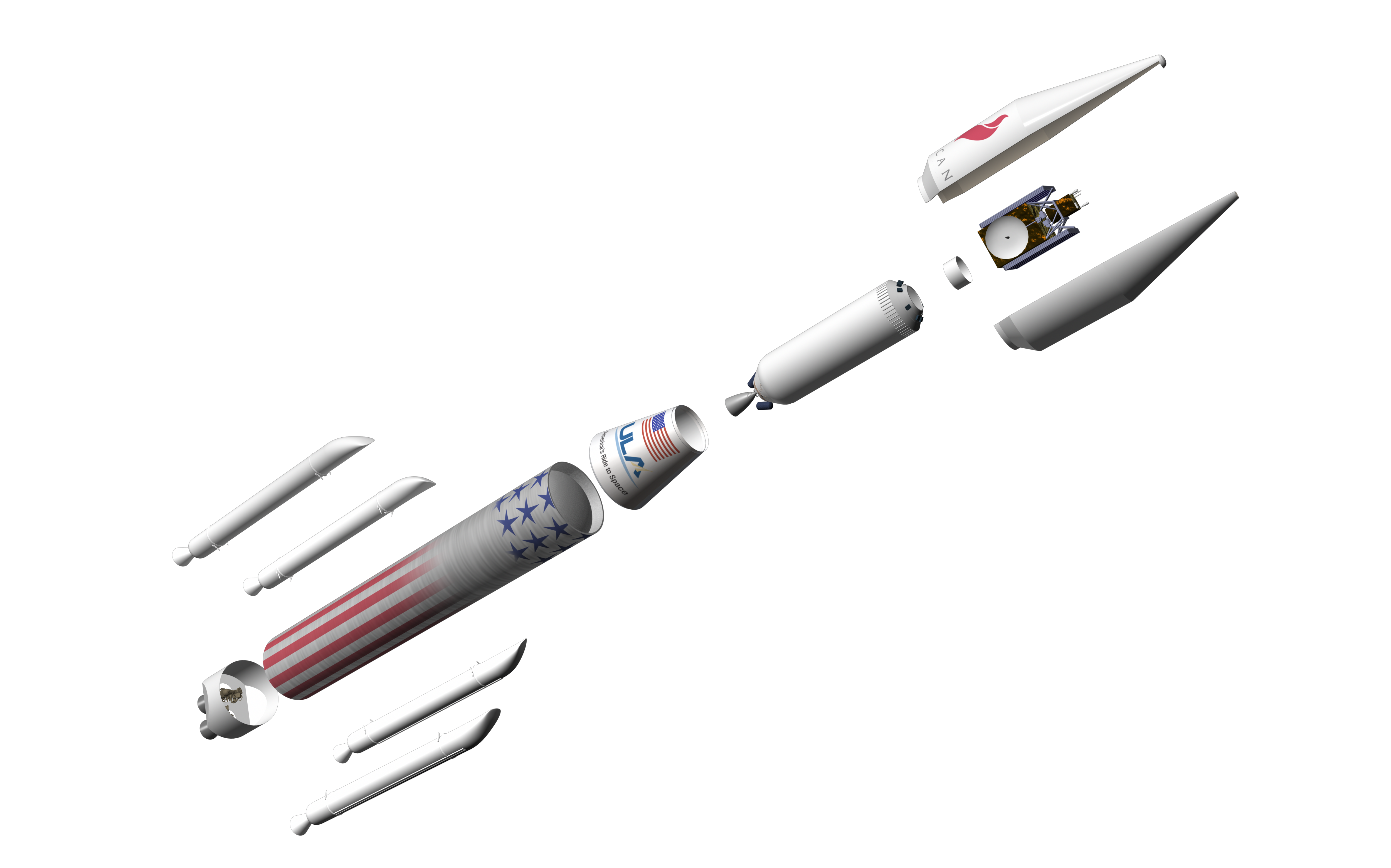
United Launch Alliance (ULA): partially-reusable Vulcan

ULA currently provides medium- and heavy-lift launch with the expendable Atlas V, Delta III and Delta IV boosters. In April 2015, ULA announced that they were developing Vulcan as their Next-Generation Launch System (NGLS) to support a wide variety of Earth-orbital and interplanetary missions. In August 2016, ULA announced plans to qualify Vulcan for manned space missions.

As shown in the following diagram, Vulcan is comprised of a liquid-fueled, two-stage core rocket that can be augmented with up to six solid rocket boosters as needed for the specific mission. This basic architecture is quite similar to ULA’s current Delta III booster, but on a larger scale.

Vulcan launch vehicle. Source: ULA

Vulcan’s maximum payload capacity is expected to fall between ULA’s current Atlas V and Delta IV boosters. ULA expects that “bare bones” Vulcan launch services will sell for half the price of an Atlas V, which is less costly to fly than the Delta IV.

The Vulcan first stage is not designed to be recovered as a unit and reused like the SpaceX Falcon. Instead, ULA is planning a future version that will be partially reusable. In this version, the engines will be designed to detach from the booster after engine cutoff, descend through the atmosphere inside a heat shield, and deploy a parachute for final descent and recovery.

European Space Agency (ESA): expendable Ariane 5 & partially-reusable Ariane 6

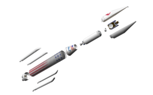
ESA’s current Ariane 5 medium- to heavy-lift booster has a two-stage, liquid-fueled core rocket flanked by two large solid rocket boosters. The basic configuration of Ariane 5 is shown in the following diagram. Ariane V is an expendable booster, not designed for reuse.

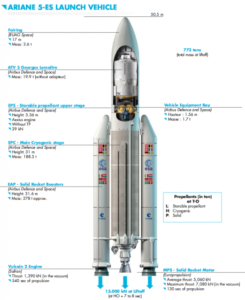
Ariane 5. Source: Arianespace

Ariane 5 first flew in June 1996 and has been employed on a wide variety of Earth orbital and interplanetary missions. Versions of Ariane 5 can deliver a payload of more than 44,000 pounds (20,000 kg) to LEO or 23,100 pounds (10,735 kg) to GTO.

In 2014, ESA announced the basic configuration of the Ariane 6 launch vehicle. Like Ariane 5, Arian 6 will have a two-stage, liquid-fueled core rocket flanked by solid rocket boosters.

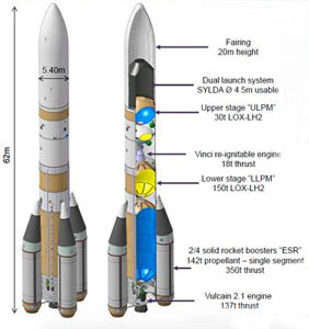
Ariane 6.  Source: adapted from BBC

Two versions are being developed:

  • Ariane 62, with two solid rocket boosters capable of launching about 11,000 pounds (5,000 kg) to GTO
  • Ariane 64, with four solid rocket boosters capable of launching about 24,000 pounds (11,000 kg) to GTO

Ariane 62 and 64 are expendable boosters, not designed for reuse.

In 2015, Airbus Defense and Space announced plans to develop a partially reusable first stage named Adeline that could enter service on a future version of Ariane 6 in the 2025 – 2030 time frame. Like ULA’s plans for Vulcan, only the Ariane 6 first stage high-value parts (i.e., the engine) would be recovered for reuse.

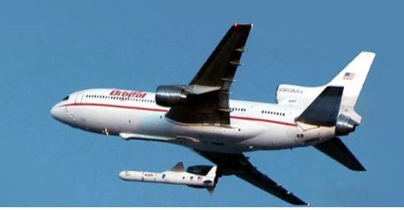
Stratolaunch Systems: giant aircraft plus potentially reusable, air-launched rocket booster

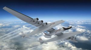
Paul Allen’s firm Stratolaunch Systems is building what will become the world’s largest aircraft, for use as an airborne launch platform for a variety of booster rockets that will take small-to-medium payloads into Earth orbit. The Stratolaunch Carrier will have two fuselages, six jet engines, a length of 238 feet (72 m), and a wingspan of 385 feet (117 m). The giant plane is designed to carry a rocket and payload with a combined weight of up to 550,000 pounds (250,000 kg) to a launch altitude of about 30,000 ft (9,144 m). Payloads up to 13,500 pounds (6,136 kg) can be delivered to LEO. The Stratolaunch Carrier can fly more than 1,000 miles to reach the launch point, giving it unprecedented operational flexibility for delivering payloads to orbit. An example mission profile is shown in the following figure.

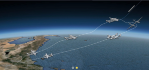
Source: Stratolaunch

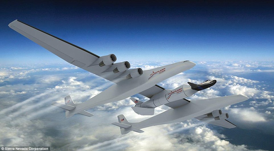
In 2014, Sierra Nevada Corporation (SNC) announced that it planned to use Stratolaunch as the launch platform for a scaled version of its Dream Chaser reusable spacecraft, initially for unmanned missions and later for manned missions with up to three astronauts. As shown in the following concept drawing, Dream Chaser appears to mounted on a winged, recoverable booster rocket.  For more information on the Dream Chaser reusable spacecraft, visit the SNC website at the following link:

https://www.sncorp.com

Stratolauncher Carrier with Dream Chaser. Source: Sierra Nevada

In 2014, a planned partnership between Stratolaunch Systems and SpaceX for an air-dropped version of the Falcon booster failed to materialize. In October 2016, Stratolaunch announced a partnership with Orbital ATK, which will provide Pegasus XL expendable boosters for use in launching small satellites into Earth orbit from the Stratolaunch aircraft.

The Stratolaunch Carrier was reported to be 76% complete in 2016. Stratolaunch Systems expects the aircraft to be operational by the end of this decade. You’ll find more information on Stratolaunch here:

http://www.stratolaunch.com

Other launch systems

You’ll find a list of worldwide orbital launch systems at the following link.  Most of these are expendable launch systems.

https://en.wikipedia.org/wiki/List_of_orbital_launch_systems

A comparison of these orbital launch systems is available here:

https://en.wikipedia.org/wiki/Comparison_of_orbital_launch_systems

Not included in the above list is the new Next Generation Launch (NGL) System announced by Orbital ATK on 6 April 2017. Two versions of this new, expendable, three-stage booster will be developed to handle medium-to-large payloads, roughly comparable to the payload capability of the SpaceX Falcon 9 reusable booster. The first two stages of the NGL System will be solid fueled.   First flight is planned for 2021. You’ll find a fact sheet on the NGL system at the following link:

http://www.orbitalatk.com/flight-systems/space-launch-vehicles/NGL/docs/BR17001_3862%20NGL_Final%20and%20Approved.pdf

In conclusion

In the highly competitive launch vehicle market, booster reusability should yield a significant economic advantage. In the long run, demonstrating better launch service economies will determine the success or failure of reusable launch vehicles.

While SpaceX and Blue Origin have demonstrated the technical ability to recover and reuse the first stage of a launch vehicle, they have not yet demonstrated the long-term economic value of that capability. In 2017, SpaceX plans to re-fly about six Falcon 9 v1.2 boosters, with even more recycled boosters to be launched in 2018. Blue Origin will likely start New Shepard passenger flights in 2018.

I’m betting that SpaceX and Blue Origin will be successful and reusable boosters will find a permanent role in reducing the price for delivering cargo and people into space.

Grand Finale of the Cassini Mission to Saturn

Peter Lobner

The National Aeronautics and Space Administration’s (NASA’s) Cassini spacecraft was launched on 15 October 1997 and cruised through interplanetary space for seven years before arriving at Saturn on 30 June 2004. The Cassini spacecraft carried the European Space Agency’s (ESA’s) Huygens probe, which landed on Saturn’s largest moon, Titan, on 14 January 2005. Since then, Cassini has been performing a series of missions in orbit around Saturn, returning spectacular images and collecting scientific data on the ringed planet and its many moons.

In 2017, Cassini is performing its Grand Finale in a highly elliptical polar orbit around Saturn. The geometry for this orbital flight path is shown in the following diagram.

Cassini_20161205cSource: NASA/JPL-Caltech

In the first phase of the Grand Finale (grey orbits in the above diagram), which is underway now, Cassini’s orbit crosses the plane of Saturn’s equatorial ring system just outside the F-ring (there are just two rings outside of the F-ring: G and E). Later in 2017, Cassini’s polar orbit will be adjusted to cross the plane of the ring system insider the innermost D-ring (blue orbits). From there the spacecraft will gradually descend toward Saturn in a region that has never before been explored. The mission will end when Cassini is destroyed somewhere in Saturn’s atmosphere (orange orbit). This is scheduled to occur on September 15, 2017 at 5:07 a.m. PDT.

NASA’s Cassini mission website is at the following link:

https://www.nasa.gov/mission_pages/cassini/main/index.html

You’ll find a NASA fact sheet on the Grand Finale here:

https://saturn.jpl.nasa.gov/legacy/files/Cassini_Grand_Finale_Fact_Sheet_508.pdf

You can follow the countdown to the final plunge into Saturn’s atmosphere and also review the entire mission timeline and other resources here:

https://saturn.jpl.nasa.gov/the-journey/timeline/#the-grand-finale

A few Grand Finale images taken during recent ring-grazing orbits past the F-ring are shown below.  The source of these three images and captions are: NASA/JPL-Caltech/Space Science Institute

Cassini_pia21056_deblurred cropThe above image, taken 16 January 2017, shows Saturn’s moon Daphnis (5 miles, 8 kilometers across), which orbits within the 26 mile (42 km) wide Keeler Gap (between the F and A rings). The gap appears foreshortened because of the viewing angle. The little moon’s gravity raises waves in the edges of the gap in both the horizontal and vertical directions.

Cassini_pia20511-1041Waves created by Daphnis are visible in this wider-angle view of the ring system. The F-ring is the bright, narrow ring crossing the center of the image. Since the moon moves in and out of the ring-plane, and closer to and farther from the rings’ edges as it orbits, the waves it makes change over time.

Cassini_pia21055-1041This image, taken on 18 December 2016, is one of the highest-resolution views ever taken of Saturn’s moon Pandora (52 miles, 84 kilometers across), which orbits just outside the F-ring.

13 April 2017 Update – Cassini’s close-up view of Saturn’s moon Pan

In early March, Cassini imaged Pan, which is one of Saturn’s innermost moons. As you can see in the following photos, this small moon (diameter of 221.7 miles, 35 km) has a most unusual shape. It isn’t known if the ridge circling the moon is solid, or a loose aggregation of particles with a very steep slope enabled by the moons weak gravity.

Source: NASA/JPL-Caltech/Space Science Institute

The NASA announcement and more photos of Pan are at the following link:

https://www.nasa.gov/image-feature/jpl/cassini-reveals-strange-shape-of-saturns-moon-pan

NuSTAR Provides a High-Resolution X-ray View of our Universe

Peter Lobner

In my 6 March 2016 post, “Remarkable Multispectral View of Our Milky Way Galaxy,” I briefly discussed several of the space-based observatories that are helping to develop a deeper understanding of our galaxy and the universe. One space-based observatory not mentioned in that post is the National Aeronautics and Space Administration (NASA) Nuclear Spectroscopic Telescope Array (NuSTAR) X-Ray observatory, which was launched on 13 June 2012 into a near equatorial, low Earth orbit. NASA describes the NuSTAR mission as follows:

“The NuSTAR mission has deployed the first orbiting telescopes to focus light in the high energy X-ray (6 – 79 keV) region of the electromagnetic spectrum. Our view of the universe in this spectral window has been limited because previous orbiting telescopes have not employed true focusing optics, but rather have used coded apertures that have intrinsically high backgrounds and limited sensitivity.

During a two-year primary mission phase, NuSTAR will map selected regions of the sky in order to:

1.  Take a census of collapsed stars and black holes of different sizes by surveying regions surrounding the center of own Milky Way Galaxy and performing deep observations of the extragalactic sky;

2.  Map recently-synthesized material in young supernova remnants to understand how stars explode and how elements are created; and

3.  Understand what powers relativistic jets of particles from the most extreme active galaxies hosting supermassive black holes.”

 The NuSTAR spacecraft is relatively small, with a payload mass of only 171 kg (377 lb). In it’s stowed configuration, this compact satellite was launched by an Orbital ATK Pegasus XL booster, which was carried aloft by the Stargazer L-1011 aircraft to approximately 40,000 feet over open ocean, where the booster was released and carried the small payload into orbit.

Orbital ATK L-1011 StargazerStargazer L-1011 dropping a Pegasus XL booster. Source: Orbital ATK

In orbit, the solar-powered NuSTAR extended to a total length of 10.9 meters (35.8 feet) in the orbital configuration shown below. The extended spacecraft gives the X-ray telescope a 10 meter (32.8 foot) focal length.

NuSTAR satelliteNuSTAR orbital configuration. Source: NASA / JPL – Caltech

NASA describes the NuSTAR X-Ray telescope as follows:

“The NuSTAR instrument consists of two co-aligned grazing incidence X-Ray telescopes (Wolter type I) with specially coated optics and newly developed detectors that extend sensitivity to higher energies as compared to previous missions such as NASA’a Chandra X-Ray Observatory launched in 1999 and the European Space Agency’s (ESA) XMM-Newton (aka High-throughput X-Ray Spectrometry Mission), also launched in 1999…….. The observatory will provide a combination of sensitivity, spatial, and spectral resolution factors of 10 to 100 improved over previous missions that have operated at these X-ray energies.”

The NASA NuSTAR mission website is at the following link:

https://www.nasa.gov/mission_pages/nustar/main/index.html

Some examples of NuSTAR findings posted on this website are summarized below.

X-ray emitting structures of galaxies identified

In the following composite image of Galaxy 1068, high-energy X-rays (shown in magenta) captured by NuSTAR are overlaid on visible-light images from both NASA’s Hubble Space Telescope and the Sloan Digital Sky Survey.

Galaxy 1068Galaxy 1068. Source: NASA/JPL-Caltech/Roma Tre Univ

Below is a more detailed X-ray view of portion of the Andromeda galaxy (aka M31), which is the galaxy nearest to our Milky Way. On 5 January 2017, NASA reported:

“The space mission has observed 40 ‘X-ray binaries’ — intense sources of X-rays comprised of a black hole or neutron star that feeds off a stellar companion.

Andromeda is the only large spiral galaxy where we can see individual X-ray binaries and study them in detail in an environment like our own.”

In the following image, the portion of the Andromeda galaxy surveyed by NuSTAR is in the smaller outlined area. The larger outlined area toward the top of this image is the corresponding X-ray view of the surveyed area.

Andromeda galaxyAndromeda galaxy.  Source: NASA/JPL-Caltech/GSFC

NASA describes the following mechanism for X-ray binaries to generate the observed intense X-ray emissions:

“In X-ray binaries, one member is always a dead star or remnant formed from the explosion of what was once a star much more massive than the sun. Depending on the mass and other properties of the original giant star, the explosion may produce either a black hole or neutron star. Under the right circumstances, material from the companion star can “spill over” its outermost edges and then be caught by the gravity of the black hole or neutron star. As the material falls in, it is heated to blazingly high temperatures, releasing a huge amount of X-rays.”

You can read more on this NuStar discovery at the following link:

https://www.nasa.gov/feature/jpl/Andromeda-Galaxy-Scanned-with-High-Energy-X-ray-Vision

Composition of supernova remnants determined

Cassiopeia A is within our Milky Way, about 11,000 light-years from Earth. The following NASA three-panel chart shows Cassiopeia A originally as an iron-core star. After going supernova, Cassiopeia A scattered its outer layers, which have distributed into the diffuse structure we see today, known as the supernova remnant. The image in the right-hand panel is a composite X-ray image of the supernova remnant from both the Chandra X-ray Observatory and NuStar.

Cassiopeia ASource: NASA/CXC/SAO/JPL-Caltech

In the following three-panel chart, the composite image (above, right) is unfolded into its components. Red shows iron and green shows both silicon and magnesium, as seen by the Chandra X-ray Observatory. Blue shows radioactive titanium-44, as mapped by NuSTAR.

 Cassiopeia A componentsSource: NASA/JPL-Caltech/CXC/SAO

Supernova 1987A is about 168,000 light-years from Earth in the Large Magellanic Cloud. As shown below, NuSTAR also observed titanium in this supernova remnant.

SN 1987A titaniumSource: NASA/JPL-Caltech/UC Berkeley

These observations are providing new insights into how massive stars explode into supernovae.

The Vision for Manned Exploration and Colonization of Mars is Alive Again

Peter Lobner

On 25 May 1961, President John F. Kennedy made an important speech to a joint session of Congress in which he stated:

“I believe that this nation should commit itself to achieving the goal, before this decade is out, of landing a man on the moon and returning him safely to the Earth.”

This was a very bold statement considering the state-of-the-art of U.S. aerospace technology in mid-1961. Yuri Gagarin became the first man to orbit the Earth on 12 April 1961 in a Soviet Vostok spacecraft and Alan Shepard completed the first Project Mercury suborbital flight on 5 May 1961. No American had yet flown in orbit. It wasn’t until 20 February 1962 that the first Project Mercury capsule flew into Earth orbit with astronaut John Glenn. The Soviets had hit the Moon with Luna 2 and returned photos from the backside of the moon with Luna 3. The U.S had only made one distant lunar flyby with the tiny Pioneer 4 spacecraft. The Apollo manned lunar program was underway, but still in the concept definition phase. The first U.S. heavy booster rocket designed to support the Apollo program, the Saturn 1, didn’t fly until 27 October 1961.

President Kennedy concluded this part of his 25 May 1961 speech with the following admonition:

“This decision (to proceed with the manned lunar program) demands a major national commitment of scientific and technical manpower, materiel and facilities, and the possibility of their diversion from other important activities where they are already thinly spread. It means a degree of dedication, organization and discipline, which have not always characterized our research and development efforts. It means we cannot afford undue work stoppages, inflated costs of material or talent, wasteful interagency rivalries, or a high turnover of key personnel.

New objectives and new money cannot solve these problems. They could in fact, aggravate them further–unless every scientist, every engineer, every serviceman, every technician, contractor, and civil servant gives his personal pledge that this nation will move forward, with the full speed of freedom, in the exciting adventure of space.”

This was the spirit that lead to the great success of the Apollo program, which landed the first men on the Moon, astronauts Neil Armstrong and Ed Aldrin, on 20 July 1969; a little more than 8 years after President Kennedy’s speech.

NASA’s plans for manned Mars exploration

By 1964, exciting concepts for manned Mars exploration vehicles were being developed under National Aeronautics and Space Administration (NASA) contract by several firms. One example is a Mars lander design shown below from Aeronutronic (then a division of Philco Corp). A Mars Excursion Module (MEM) would descend to the surface of Mars from a larger Mars Mission Module (MMM) that remained in orbit. The MEM was designed for landing a crew of three on Mars, spending 40 days on the Martian surface, and then returning the crew back to Mars orbit and rendezvousing with the MMM for the journey back to Earth.

1963 Aeronutronic Mars lander conceptSource: NASA / Aviation Week 24Feb64

This and other concepts developed in the 1960s are described in detail in Chapters 3 – 5 of NASA’s Monograph in Aerospace History #21, “Humans to Mars – Fifty Years of Mission Planning, 1950 – 2000,” which you can download at the following link:

http://www.nss.org/settlement/mars/2001-HumansToMars-FiftyYearsOfMissionPlanning.pdf

In the 1960’s the U.S. nuclear thermal rocket development program led to the development of the very promising NERVA nuclear engine for use in an upper stage or an interplanetary spacecraft. NASA and the Space Nuclear Propulsion Office (SNPO) felt that tests had “confirmed that a nuclear rocket engine was suitable for space flight application.”

In 1969, Marshall Space Flight Director Wernher von Braun propose sending 12 men to Mars aboard two rockets, each propelled by three NERVA engines. This spacecraft would have measured 270 feet long and 100 feet wide across the three nuclear engine modules, with a mass of 800 tons, including 600 tons of liquid hydrogen propellant for the NERVA engines. The two outboard nuclear engine modules only would be used to inject the spacecraft onto its trans-Mars trajectory, after which they would separate from the spacecraft. The central nuclear engine module would continue with the manned spacecraft and be used to enter and leave Mars orbit and enter Earth orbit at the end of the mission. The mission would launch in November 1981 and land on Mars in August 1982.

Marshall 1969 NERVA mars missionNERVA-powered Mars spacecraft. Source: NASA / Monograph #21

NASA’s momentum for conducting a manned Mars mission by the 1980s was short-lived. Development of the super heavy lift Nova booster, which was intended to place about 250 tons to low Earth orbit (LEO), was never funded. Congress reduced NASA’s funding in the FY-69 budget, resulting in NASA ending production of the Saturn 5 heavy-lift booster rocket (about 100 tons to LEO) and cancelling Apollo missions after Apollo 17. This left NASA without the heavy-lift booster rocket needed to carry NERVA and/or assembled interplanetary spacecraft into orbit.

NASA persevered with chemical rocket powered Mars mission concepts until 1971. The final NASA concept vehicle from that era, looking much like von Braun’s 1969 nuclear-powered spacecraft, is shown below.

NASA 1971 mars concept

Source: NASA / Monograph #21

The 24-foot diameter modules would have required six Shuttle-derived launch vehicles (essentially the large center tank and the strap-in solid boosters, without the Space Shuttle itself) to deliver the various modules for assembly in orbit.

While no longer a factor in Mars mission planning, the nuclear rocket program was canceled in 1972. You can read a history of the U.S. nuclear thermal rocket program at the following links:

http://www.lanl.gov/science/NSS/issue1_2011/story4full.shtml

and,

http://ntrs.nasa.gov/archive/nasa/casi.ntrs.nasa.gov/19910017902.pdf

NASA budget realities in subsequent years, dictated largely by the cost of Space Shuttle and International Space Station development and operation, reduced NASA’s manned Mars efforts to a series of design studies, as described in the Monograph #21.

Science Applications International Corporation (SAIC) conducted manned Mars mission studies for NASA in 1984 and 1987. The latter mission design study was conducted in collaboration with astronaut Sally Ride’s August 1987 report, Leadership and America’s Future in Space. You can read this report at the following link.

http://history.nasa.gov/riderep/cover.htm

Details on the 1987 SAIC mission study are included in Chapter 8 of the Monograph #21. SAIC’s mission concept employed two chemically-fueled Mars spacecraft in “split/sprint” roles. An automated cargo-carrying spacecraft would be first to depart Earth. It would fly an energy-saving trajectory and enter Mars orbit carrying the fuel needed by the future manned spacecraft for its return to Earth. After the cargo spacecraft was in Mars orbit, the manned spacecraft would be launched on a faster “sprint” trajectory, taking about six months to get to Mars. With one month allocated for exploration of the Martian surface, total mission time would be on the order of 12 – 14 months.

President Obama’s FY-11 budget redirected NASA’s focus away from manned missions to the Moon and Mars. The result is that there are no current programs with near-term goals to establish a continuous U.S. presence on the Moon or conduct the first manned mission to Mars. Instead, NASA is engaged in developing hardware that will be used initially for a relatively near-Earth (but further out than astronauts have gone before) “asteroid re-direct mission.” NASA’s current vision for getting to Mars is summarized below.

  • In the 2020s, NASA will send astronauts on a year-long mission into (relatively near-Earth) deep space, verifying spacecraft habitation and testing our readiness for a Mars mission.
  • In the 2030s, NASA will send astronauts first to low-Mars orbit. This phase will test the entry, descent and landing techniques needed to get to the Martian surface and study what’s needed for in-situ resource utilization.
  • Eventually, NASA will land humans on Mars.

You can read NASA’s Journey to Mars Overview at the following link:

https://www.nasa.gov/content/journey-to-mars-overview

NASA’s current plans for getting to Mars don’t really sound like much of a plan to me. Think back to President Kennedy’s speech that outlined the national commitment needed to accomplish a lunar landing within the decade of the 1960s. There is no real sense of timeliness in NASA plans for getting to Mars.

Thinking back to the title of NASA’s Monograph #21, “Humans to Mars – Fifty Years of Mission Planning, 1950 – 2000,” I’d say that NASA is quite good at manned Mars mission planning, but woefully short on execution. I recognize that NASA’s ability to execute anything is driven by its budget. However, in 1969, Wernher von Braun thought the U.S. was about 12 years from being able to launch a nuclear-powered manned Mars mission in 1981. Now it seems we’re almost 20 years away, with no real concept for the spacecraft that will get our astronauts there and back.

Commercial plans for manned Mars exploration

Fortunately, the U.S. commercial aerospace sector seems more committed to conducting manned Mars missions than NASA. The leading U.S. contenders are Bigelow Aerospace and SpaceX. Let’s look at their plans.

Bigelow Aerospace

Bigelow is developing expandable structures that can be used to house various types of occupied spaces on manned Earth orbital platforms or on spacecraft destined for lunar orbital missions or long interplanetary missions. Versions of these expandable structures also can be used for habitats on the surface of the Moon, Mars, or elsewhere.

The first operational use of this type of expandable structure in space occurred on 26 May 2016, when the BEAM (Bigelow Expandable Activity Module) was deployed to its full size on the International Space Station (ISS). BEAM was expanded by air pressure from the ISS.

Bigelow BEAMBEAM installed in the ISS. Source: Bigelow Aerospace

You can view a NASA time-lapse video of BEAM deployment at the following link:

https://www.youtube.com/watch?v=QxzCCrj5ssE

A large, complex space vehicle can be built with a combination of relatively conventional structures and Bigelow inflatable modules, as shown in the following concept drawing.

Bigelow spacecraft conceptSource: Bigelow Aerospace

A 2011 NASA concept named Nautilus-X, also making extensive use of inflatable structures, is shown in the following concept drawing. Nautilus is an acronym for Non-Atmospheric Universal Transport Intended for Lengthy United States Exploration.

NASA Nautilus-X-space-exploration-vehicle-concept-1

Source: NASA / NASA Technology Applications Assessment Team

SpaceX

SpaceX announced that it plans to send its first Red Dragon capsule to Mars in 2018 to demonstrate the ability to land heavy loads using a combination of aero braking with the capsule’s ablative heat shield and propulsive braking using rocket engines for the final phase of landing.

Red Dragon landing on MarsSource: SpaceX

More details on the Red Dragon spacecraft are in a 2012 paper by Karcs, J. et al., entitled, “Red Dragon: Low-cost Access to the Surface of Mars Using Commercial Capabilities,” which you’ll find at the following link:

https://www.nas.nasa.gov/assets/pdf/staff/Aftosmis_M_RED_DRAGON_Low-Cost_Access_to_the_Surface_of_Mars_Using_Commercial_Capabilities.pdf

NASA is collaborating with SpaceX to gain experience with this landing technique, which NASA expects to employ in its own future Mars missions.

On 27 September 2016, SpaceX CEO Elon Musk unveiled his grand vision for colonizing Mars at the 67th International Astronautical Congress in Guadalajara, Mexico. You’ll find an excellent summary in the 29 September 2016 article by Dave Mosher entitled, “Elon Musk’s complete, sweeping vision on colonizing Mars to save humanity,” which you can read on the Business Insider website at the following link:

http://www.businessinsider.com/elon-musk-mars-speech-transcript-2016-9

The system architecture for the SpaceX colonizing flights is shown in the following diagram. Significant features include:

  • 100 passengers on a one-way trip to Mars
  • Booster and spacecraft are reusable
  • No spacecraft assembly in orbit required.
  • The manned interplanetary vehicle is fueled with methane in Earth orbit from a tanker spacecraft.
  • The entire manned interplanetary vehicle lands on Mars. There is no part of the vehicle left orbiting Mars.
  • The 100 passengers disembark to colonize Mars
  • Methane fuel for the return voyage to Earth is manufactured on the surface of Mars.
  • The spacecraft returns to Earth for reuse on another mission.
  • Price per person for Mars colonists could be in the $100,000 to $200,000 range.

The Mars launcher for this mission would have a gross lift-off mass of 10,500 tons; 3.5 times the mass of NASA’s Saturn 5 booster for the Apollo Moon landing program.

SpaceX colonist architectureSource: SpaceX

 Terraforming Mars

Colonizing Mars will require terraforming to transform the planet so it can sustain human life. Terraforming the hostile environment of another planet has never been done before. While there are theories about how to accomplish Martian terraforming, there currently is no clear roadmap. However, there is a new board game named, “Terraforming Mars,” that will test your skills at using limited resources wisely to terraform Mars.

Nate Anderson provides a detailed introduction to this board game in his 1 October 2016 article entitled, “Terraforming Mars review: Turn the ‘Red Planet’ green with this amazing board game,” which you can read at the following link:

http://arstechnica.com/gaming/2016/10/terraforming-mars-review/?utm_source=howtogeek&utm_medium=email&utm_campaign=newsletter

71RW5ZM0bBL._SL1000_Source: Stronghold GamesTerraforming Mars gameboardSource: Nate Anderson / arsTECHNICA

Nate Anderson described the game as follows:

“In Terraforming Mars, you play one of several competing corporations seeking to terraform the Red Planet into a livable—indeed, hospitable—place filled with cows, dogs, fish, lichen, bacteria, grasslands, atmosphere, and oceans. That goal is achieved when three things happen: atmospheric oxygen rises to 14 percent, planetary temperature rises to 8°C, and all nine of the game’s ocean tiles are placed.

Real science rests behind each of these numbers. The ocean tiles each represent one percent coverage of the Martian surface; once nine percent of the planet is covered with water, Mars should develop its own sustainable hydrologic cycle. An atmosphere of 14 percent oxygen is breathable by humans (though it feels like a 3,000 m elevation on Earth). And at 8°C, water will remain liquid in the Martian equatorial zone.

Once all three milestones have been achieved, Mars has been successfully terraformed, the game ends, and scores are calculated.”

The players are competing corporations, each with limited resources. The game play evolves based how each player (corporation) chooses to spend their resources to build their terraforming engines (constrained by some rules of precedence), and the opportunities dealt to them in each round.

You can buy the game Terraforming Mars on Amazon.

So, before you sign up with SpaceX to become a Martian colonist, practice your skills at terraforming Mars. You’ll be in high demand as an expert terraformer when you get to Mars on a SpaceX colonist ship in the late 2020s.

Exploring Microgravity Worlds

Peter Lobner

1.  Background:

We’re all familiar with scenes of the Apollo astronauts bounding across the lunar surface in the low gravity on the Moon, where gravity (g) is 0.17 of the gravity on the Earth’s surface. Driving the Apollo lunar rover kicked up some dust, but otherwise proved to be a practical means of transportation on the Moon’s surface. While the Moon’s gravity is low relative to Earth, techniques for achieving lunar orbit have been demonstrated by many spacecraft, many soft landings have been made, locomotion on the Moon’s surface with wheeled vehicles has worked well, and there is no risk of flying off into space by accidentally exceeding the Moon’s escape velocity.

There are many small bodies in the Solar System (i.e., dwarf planets, asteroids, comets) where gravity is so low that it creates unique problems for visiting spacecraft and future astronauts: For example:

  • Spacecraft require efficient propulsion systems and precise navigation along complex trajectories to rendezvous with the small body and then move into a station-keeping position or establish a stable orbit around the body.
  • Landers require precise navigation to avoid hazards on the surface of the body (i.e., craters, boulders, steep slopes), land gently in a specific safe area, and not rebound back into space after touching down.
  • Rovers require a locomotion system that is adapted to the specific terrain and microgravity conditions of the body and allows the rover vehicle to move across the surface of the body without risk of being launched back into space by reaction forces.
  • Many asteroids and comets are irregularly shaped bodies, so the surface gravity vector will vary significantly depending on where you are relative to the center of mass of the body.

You will find a long list of known objects in the Solar System, including many with diameters less than 1 km (0.62 mile), at the following link:

https://en.wikipedia.org/wiki/List_of_Solar_System_objects_by_size

You can determine the gravity on the surface of a body in the Solar System using the following equation:

Equation for g

where (using metric):

g = acceleration due to gravity on the surface of the body (m/sec2)

G = universal gravitational constant = 6.672 x 10⁻¹¹ m3/kg/sec2

M = mass of the body (kg)

r = radius of the body (which is assumed to be spherical) (m)

You can determine the escape velocity from a body using the following equation:

Equation - Escape velocity

Applying these equations to the Earth and several smaller bodies in in the Solar System yields the following results:

g and escape velocity table

Note how weak the gravity is on the small bodies in this table. These are very different conditions than on the surface of the Moon or Mars where the low gravity still allows relatively conventional locomotion.

As noted in my 31 December 2015 post, the “U.S. Commercial Space Launch Competitiveness Act,” which was signed into law on 25 November 2015, opens the way for U.S. commercial exploitation of space, including commercial missions to asteroids and comets.  Let’s take a look at missions to these microgravity worlds and some of the unique issues associated with visiting a microgravity world.

2.  Recent and Current Missions to Asteroids and Comets

There have been several spacecraft that have made a successful rendezvous with one or more small bodies in the Solar System. Several have been fly-by missions. Four spacecraft have flown in close formation with or entered orbit around low-gravity bodies. Three of these missions included landing on (or at least touching) the body, and one returned very small samples to Earth. These missions are:

  • National Aeronautics and Space Administration’s (NASA) NEAR-Shoemaker
  • Japan Aerospace Exploration Agency’s (JAXA) Hayabusa
  • European Space Agency’s (ESA) Rosetta
  • NASA’s Dawn

In addition, China’s Chang’e 2 mission demonstrated its ability to navigate to an asteroid intercept after completing its primary mission in lunar orbit. JAXA’s Hayabusa 2 mission currently is enroute to asteroid rendezvous.

Following is a short synopsis of each of these missions.

NASA’s NEAR-Shoemaker Mission (1996 – 2001): This mission was launched 17 February 1996 and on 27 June 1997 flew by the asteroid 253 Mathilde at a distance of about 1,200 km (746 miles).   On 14 February 2000, the spacecraft reached its destination and entered a near-circular orbit around the asteroid 433 Eros, which is about the size of Manhattan. After completing its survey of Eros, the NEAR spacecraft was maneuvered close to the surface and it touched down on 12 February 2001, after a four-hour descent, during which it transmitted 69 close-up images of the surface. Transmissions continued for a short time after landing. NEAR-Shoemaker was the first man-made object to soft-land on an asteroid.

Asteroid Eros                Asteroid EROS. Source: NASA/JPL/JHUAPL

JAXA’s Hayabusa Mission (2003 – 2010): The Hayabusa spacecraft was launched in May 2003. This solar-powered, ion-driven spacecraft rendezvoused with near-Earth asteroid 25143 Itokawa in mid-September 2005.

Asteroid Itokawa           Asteroid Itokawa. Source: JAXA

Hayabusa carried the solar-powered MINERVA (Micro/Nano Experimental Robot Vehicle for Asteroid) mini-lander, which was designed to be released close to the asteroid, land softly, and move across the surface using an internal flywheel and braking system to generate the momentum needed to hop in microgravity. However, MINERVA was not captured by the asteroid’s gravity after being released and was lost in deep space.

In November 2005, Hayabusa moved in from its station-keeping position and briefly touched the asteroid to collect surface samples in the form of tiny grains of asteroid material.

Hayabusa taking a sampleHayabusa in position to obtain samples. Source: JAXA

The spacecraft then backed off and navigated back to Earth using its failing ion thrusters. Hayabusa returned to Earth on 13 June 2010 and the sample-return capsule, with about 1,500 grains of asteroid material, was recovered after landing in the Woomera Test Range in the western Australian desert.

You’ll find a JAXA mission summary briefing at the following link:

https://www.nasa.gov/pdf/474206main_Kuninaka_HayabusaStatus_ExploreNOW.pdf

ESA’s Rosetta Mission (2004 – present): The Rosetta spacecraft was launched in March 2004 and in August 2014 rendezvoused with and achieved orbit around irregularly shaped comet 67P/Churyumov-Gerasimenko. This comet orbits the Sun outside of Earth’s orbit, between 1.24 and 5.68 AU (astronomical units; 1 AU = average distance from Earth’s orbit to the Sun). The size of 67P/Churyumov-Gerasimenko is compared to downtown Los Angeles in the following figure.

ESA Attempts To Land Probe On CometSource: ESA

Currently, Rosetta remains in orbit around this comet. The lander, Philae, is on the surface after a dramatic rebounding landing on 12 November 2014. Anchoring devices failed to secure Philae after its initial touchdown. The lander bounced twice and finally came to rest in an unfavorable position after contacting the surface a third time, about two hours after the initial touchdown. Philae was the first vehicle to land on a comet and it briefly transmitted data back from the surface of the comet in November 2014 and again in June – July 2015.

NASA’s Dawn Mission (2007 – present): Dawn was launched on 27 September 2007 and used its ion engine to fly a complex flight path to a 2009 gravitational assist flyby of Mars and then a rendezvous with the large asteroid Vesta (2011 – 2012) in the main asteroid belt.

NASA_Dawn_spacecraft_near_Ceres   Dawn approaches Vesta. Source: NASA / JPL Caltech

Dawn spent 14 months in orbit surveying Vesta before departing to its next destination, the dwarf planet Ceres, which also is in the main asteroid belt. On 6 March 2015 Dawn was captured by Ceres’ gravity and entered its initial orbit following the complex trajectory shown in the following diagram.

Dawn navigation to Ceres orbit   Dawn captured by Ceres gravity. Source: NASA / JPL Caltech

Dawn is continuing its mapping mission in a circular orbit at an altitude of 385 km (240 miles), circling Ceres every 5.4 hours at an orbital velocity of about 983 kph (611 mph). The Dawn mission does not include a lander.

See my 20 March 2015 and 13 Sep 2015 posts for more information on the Dawn mission.

CNSA’s Chang’e 2 extended mission (2010 – present): The China National Space Agency’s (CNSA) Chang’e 2 spacecraft was launched in October 2010 and placed into a 100 km lunar orbit with the primary objective of mapping the lunar surface. After completing this objective in 2011, Chang’e 2 navigated to the Earth-Sun L2 Lagrange point, which is a million miles from Earth in the opposite direction of the Sun. In April 2012, Chang’e 2 departed L2 for an extended mission to asteroid 4179 Toutatis, which it flew by in December 2012.

Toutatis_from_Chang'e_2Asteroid Toutatis. Source: CHSA

JAXA’s Hayabusa 2 Mission (2014 – 2020): The JAXA Hayabusa 2 spacecraft was launched on 3 December 2014. This ion-propelled spacecraft is very similar to the first Hayabusa spacecraft. Its planned arrival date at the target asteroid, 1999 JU3 (Ryugu), is in mid-2018.   As you can see in the following diagram, 1999 JU3 is a substantially larger asteroid than Itokawa.

Hayabusa 1-2 target comparisonSource: JAXA

The spacecraft will spend about a year mapping the asteroid using Near Infrared Spectrometer (NIRS3) and Thermal Infrared Imager (TIR) instruments.

Hayabusa 2 includes three solar-powered MINERVA-II mini-landers and one battery-powered MASCOT (Mobile Asteroid Surface Scout) small lander. All landers will be deployed to the asteroid surface from an altitude of about 100 meters (328 feet) so they can be captured by the asteroid’s very weak gravity. The 1.6 – 2.5 kg (3.5 – 5.5 pounds) MINERVA-II landers will deliver imagery and temperature measurements. The 10 kg (22 pound) MASCOT will make measurements of surface composition and properties using a camera, magnetometer, radiometer, and infrared microscope. All landers are expected to make several hops to take measurements at different locations on the asteroid’s surface.

Three MINERVA landers

Three MINERVA mini-landers. Source: JAXA

MASCOT lander         MASCOT small lander. Source: JAXA

For sample collection, Hayabusa 2 will descend to the surface to capture samples of the surface material. A device called a Small Carry-on Impactor (SCI) will be deployed and should impact the surface at about 2 km/sec, creating a small crater to expose material beneath the asteroid’s surface. Hayabusa 2 will attempt to gather a sample of the exposed material. More information about SCI is available at the following link:

http://www.lpi.usra.edu/meetings/lpsc2013/pdf/1904.pdf

At the end of 2019, Hayabusa 2 is scheduled to depart asteroid 1999 JU3 (Ryugu) and return to Earth in 2020 with the collected samples. You will find more information on the Hayabusa 2 mission at the JAXA website at the following links:

http://global.jaxa.jp/projects/sat/hayabusa2/

and,

http://www.lpi.usra.edu/sbag/meetings/jan2013/presentations/sbag8_presentations/TUES_0900_Hayabusa-2.pdf

3.  Future Missions:

NASA OSIRIS-REx: This NASA’s mission is expected to launch in September 2016, travel to the near-Earth asteroid 101955 Bennu, map the surface, harvest a sample of surface material, and return the samples to Earth for study. After arriving at Bennu in 2018, the solar-powered OSIRIS-Rex spacecraft will map the asteroid surface from a station-keeping distance of about 5 km (3.1 miles) using two primary mapping instruments: the OVIRS Visible and Infrared Spectrometer and the OTRS Thermal Emission Spectrometer. Together, these instruments are expected to develop a comprehensive map of Bennu’s mineralogical and molecular components and enable mission planners to target the specific site(s) to be sampled. In 2019, a robotic arm on OSIRIS-REx will collect surface samples during one or more very close approaches, without landing. These samples (60 grams minimum) will be loaded into a small capsule that is scheduled to return to Earth in 2023.

OSIRIS-REx SpacecraftOSIRIS-REx spacecraft. Source: NASA / ASU

For more information on OSIRIS-REx, visit the NASA website at the following link:

http://sservi.nasa.gov/articles/nasas-asteroid-sample-return-mission-moves-into-development/

and the ASU website at the following link:

http://www.asteroidmission.org/objectives/

NASA Asteroid Redirect Mission (ARM): This mission will involve rendezvousing with a near-Earth asteroid, mapping the surface for about a year, and locating a suitable bolder to be captured [maximum diameter about 4 meters (13.1 feet)]. The ARM spacecraft will land and capture the intended bolder, lift off and deliver the bolder into a stable lunar orbit during the first half of the next decade. The current reference target is known as asteroid 2008 EV5.

ARM asteroid-capture      ARM lander gripping a bolder on an asteroid. Source: NASA

You can find more information on the NASA Asteroid Redirect Mission at the following links:

https://www.nasa.gov/content/what-is-nasa-s-asteroid-redirect-mission

and

https://www.nasa.gov/pdf/756122main_Asteroid%20Redirect%20Mission%20Reference%20Concept%20Description.pdf

4. Locomotion in Microgravity

OK, you’ve landed on a small asteroid, your spacecraft has anchored itself to the surface and now you want to go out and explore the surface. If this is asteroid 2008 EV5, the local gravity is about 1.79 E-05 that of Earth (less than 2/100,000 the gravity of Earth) and the escape velocity is about 0.6 mph (1 kph). Just how are you going to move about on the surface and not launch yourself on an escape trajectory into deep space?

There is a good article on the problems of locomotion in microgravity in a 7 March 2015 article entitled, “A Lightness of Being,” in the Economist magazine. You can find this article on the Economist website at the following link:

http://www.economist.com/news/technology-quarterly/21645508-space-vehicles-can-operate-ultra-low-gravity-asteroids-and-comets-are

In this article, it is noted that:

“Wheeled and tracked rovers could probably be made to work in gravity as low as a hundredth of that on Earth……But in the far weaker microgravity of small bodies like asteroids and comets, they would fail to get a grip in fine regolith. Wheels also might hover above the ground, spinning hopelessly and using up power. So an entirely different system of locomotion is needed for rovers operating in a microgravity.”

Novel concepts for locomotion in microgravity include:

  • Hoppers / tumblers
  • Structurally compliant rollers
  • Grippers

Hoppers / tumblers: Hoppers are designed to move across a surface using a moving internal mass that can be controlled to transfer momentum to the body of the rover to cause it to tumble or to generate a more dramatic hop, which is a short ballistic trajectory in microgravity. The magnitude of the hop must be controlled so the lander does not exceed escape velocity during a hop. JAXA’s MINERVA-II and MASCOT asteroid landers both are hoppers.

JAXA described the MINERVA-II hopping mechanism as follows:

“MINERVA can hop from one location to another using two DC motors – the first serving as a torquer, rotating an internal mass that leads to a resulting force, sufficient to make the rover hop for several meters. The second motor rotates the table on which the torquer is placed in order to control the direction of the hop. The rover reaches a top speed of 9 centimeters per second, allowing it to hop a considerable distance.”

JAXA MINERVA hopperMINERVA torque & turntable. Source: JAXA

The MASCOT hopper operates on a different principle:

“With a mass of not even half a gram in the gravitational field of the asteroid, the (MASCOT) lander can easily withstand its initial contact with the surface and several bounces that are expected upon landing. It also means that only small forces are needed to move the lander from point to point. MASCOT’s Mobility System essentially consists of an off-centered mass installed on an eccentric arm that moves that mass to generate momentum that is sufficient to either rotate the lander to face the surface with its instruments or initiate a hop of up to 70 meters to get to the next sampling site.”

MASCOT Mobility SystemMASCOT mobility mechanism. Source: JAXA

You will find a good animation of MASCOT and its Mobility System at the following link:

http://www.dlr.de/dlr/en/desktopdefault.aspx/tabid-10081/151_read-18664/#/gallery/23722

NASA is examining a class of microgravity rovers called “hedgehogs” that are designed to hop and tumble on microgravity surfaces by spinning and braking a set of three internal flywheels. Cushions or spikes at the corners of the cubic body of a hedgehog protect the body from the terrain and act as feet while hopping and tumbling.

NASA Hedgehog                               NASA Hedgehog prototype. Source: NASA

Read more on the NASA hedgehog rovers at the following link:

http://www.jpl.nasa.gov/news/news.php?feature=4712

Structurally compliant rollers: One means of “rolling” across a microgravity surface is with a deformable structure that allows the location of the center of mass to be controlled in a way that causes the rover to tip over in the desired direction of motion. NASA is exploring the use of a class of rolling rovers called Super Ball Bots, which are terrestrial rovers based on a R. Buckminster Fuller’s tensegrity toy. NASA explains:

“The Super Ball Bot has a sphere-like matrix of cables and joints that could withstand being dropped from a spacecraft high above a planetary surface and hit the ground with a bounce. Once on the planet, the joints could adjust to roll the bot in any direction while housing a data collecting device within its core.”

NASA Super Ball Bot                    Source: http://www.nasa.gov/content/super-ball-bot

You’ll find a detailed description of the principles behind tensegrity (tensional integrity) in a 1961 R. Buckminster Fuller paper at the following link:

http://www.rwgrayprojects.com/rbfnotes/fpapers/tensegrity/tenseg01.html

Grippers: Without having a grip on a microgravity body, a rover cannot use sampling tools that generate a reaction force on the rover (i.e., drills, grinders, chippers). For such operations to be successful a rover needs an anchoring system to secure the rover and transfer the reaction loads into the microgravity body.

An approach being developed by Jet Propulsion Laboratory (JPL) involves articulated feet with microspine grippers that have a large number of small claws that can grip irregular rocky surfaces.

JPL microspine gripper           Microspine gripper. Source: NASA / JPL

Such a gripper could be used to hold a rover in place during mechanical sampling activities or to allow a rover to climb across an irregular surface like a spider.  See more about the operation of the NASA / JPL microspine gripper at the following link:

https://www-robotics.jpl.nasa.gov/tasks/taskVideo.cfm?TaskID=206&tdaID=700015&Video=147

5. Conclusions

Missions to small bodies in our Solar System are very complex undertakings that require very advanced technologies in many areas, including: propulsion, navigation, autonomous controls, remote sensing, and locomotion in microgravity. The ambitious current and planned future missions will greatly expand our knowledge of these small bodies and the engineering required to operate spacecraft in their vicinity and on their surface.

While commercial exploitation of dwarf planets, asteroids and comets still may sound like science fiction, the technical foundation for such activities is being developed now. It’s hard to guess how much progress will be made in the next decades. However, I’m convinced that the “U.S. Commercial Space Launch Competitiveness Act,” will encourage commercial investments in space exploration and exploitation and lead to much greater progress than if we depended on NASA alone.

The technologies being developed also may lead, in the long term, to effective techniques for redirecting an asteroid or comet that poses a threat to Earth. Such a development would give our Planetary Defense Officer (see my 21 January 2016 post) an actual tool for defending the planet.

Remarkable Multispectral View of Our Milky Way Galaxy

Peter Lobner, updated 18 August 2023

Moody Blues cover - In search of the lost chordAlbum Album cover art credit: Deram Records

Some of you may recall the following lyrics from the 1968 Moody Blues song, “The Word,” by Graeme, Edge, from the album “In Search of the Lost Chord”:

This garden universe vibrates complete

Some, we get a sound so sweet

 Vibrations reach on up to become light

And then through gamma, out of sight

Between the eyes and ears there lie

The sounds of color and the light of a sigh

And to hear the sun, what a thing to believe

But it’s all around if we could but perceive

 To know ultraviolet, infrared and X-rays

Beauty to find in so many ways

On 24 February 2016, the European Southern Observatory (ESO) Consortium announced that it has completed the ATLASGAL Survey of the Milky Way. The survey mapped the entire galactic plane visible from the southern hemisphere at sub-millimeter wavelengths, between infrared light and radio waves, using the Atacama Pathfinder EXperiment (APEX) telescope located at 5,100 meters (16,732 ft.) above sea level in Chile’s Atacama region. The southern sky is particularly important because it includes the galactic center of our Milky Way. The Milky Way in the northern sky has already been mapped by the James Clerk Maxwell Telescope, which is a sub-millimeter wavelength telescope at the Mauna Kea Observatory in Hawaii.

The new ATLASGAL maps cover an area of sky 140 degrees long and 3 degrees wide. ESO stated that these are the sharpest maps yet made, and they complement those from other land-based and space-based observatories. The principal space-based observatories are the following:

  • European Space Agency’s (ESA) Plank satellite: Mission on-going, mapping anisotropies of the cosmic microwave background at microwave and infrared frequencies.
  • ESA’s Herschel Space Observatory: Mission on-going, conducting sky surveys in the far-infrared and sub-millimeter frequencies.
  • National Aeronautics and Space Administration (NASA) Spitzer Space Telescope: Mission on-going, conducting infrared observations and mapping as described in my 1 April 2015 post.
  • NASA’s Hubble Space Telescope: Mission on-going, observing and mapping at ultraviolet, optical, and infrared frequencies.
  • NASA’s Chandra X-Ray Observatory: Mission on-going, observing and mapping X-ray sources.
  • NASA’s Compton Gamma Ray Observatory: Mission ended in 2000. Observed and mapped gamma ray and x-ray sources.

ESO reported that the combination of Planck and APEX data allowed astronomers to detect emission spread over a larger area of sky and to estimate from it the fraction of dense gas in the inner galaxy. The ATLASGAL data were also used to create a complete census of cold and massive clouds where new generations of stars are forming.

You can read the ESO press release at the following link:

https://www.eso.org/public/news/eso1606/

Below is a composite ESO photograph that shows the same central region of the Milky Way observed at different wavelengths.

ESO Multispectral view of Milky WaySource: ESO/ATLASGAL consortium/NASA/GLIMPSE consortium/VVV Survey/ESA/Planck/D. Minniti/S. Guisard. Acknowledgement: Ignacio Toledo, Martin Kornmesser

  • The top panel shows compact sources of sub-millimeter radiation detected by APEX as part of the ATLASGAL survey, combined with complementary data from ESA’s Planck satellite, to capture more extended features.
  • The second panel shows the same region as seen in shorter, infrared wavelengths by the NASA Spitzer Space Telescope
  • The third panel shows the same part of sky again at even shorter wavelengths, the near-infrared, as seen by ESO’s VISTA infrared survey telescope at the Paranal Observatory in Chile. Regions appearing as dark dust tendrils in the third panel show up brightly in the ATLASGAL view (top panel).
  • The bottom panel shows the more familiar view in visible light, where most of the more distant structures are hidden from view

NASA’s Goddard Space Flight Center also  created a multispectral view of the Milky Way, which  is shown in the following composite photograph of the same central region of the Milky Way observed at different wavelengths.

NASA Goddard multispectralSource: NASA Goddard Space Flight Center

Starting from the top, the ten panels in the NASA image cover the following wavelengths.

  • Radio frequency (408 MHz)
  • Atomic hydrogen
  • Radio frequency (2.5 GHz)
  • Molecular hydrogen
  • Infrared
  • Mid-infrared
  • Near-infrared
  • Optical
  • X-ray
  • Gamma ray

The Moody Blues song, “The Word,” ends with the following lyrics:

 Two notes of the chord, that’s our full scope

But to reach the chord is our life’s hope

And to name the chord is important to some

So they give it a word, and the word is “Om”

While “Om” (pronounced or hummed “ahh-ummmm”) traditionally is a sacred mantra of Hindu, Jain and Buddhist religions, it also may be the mantra of astronomers as they unravel new secrets of the Milky Way and, more broadly, the Universe. I suspect that completing the ATLASGAL Survey of the Milky Way was an “Om” moment for the many participants in the ESO Consortium effort.

For more information