Category Archives: Spacecraft and Missions

Philae Found in a Rocky Ditch on Comet 67P/Churyumov-Gerasimenko

Peter Lobner

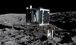
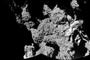
In my 24 August 2016 post, “Exploring Microgravity Worlds,” I described the European Space Agency’s (ESA’s) Rosetta mission to comet 67P and the Philae lander, which was intended to make a soft landing on 67P and attach itself to the surface. However, the securing devices (a pair of harpoons and screws on each leg) failed to work upon touching the surface the first time. In the microgravity environment of 67P, Philae rebounded and eventually came to rest adjacent to a rocky outcropping seen in a post-landing photo.

Rosetta_Auto52Main components of the Philae lander. Source: Philae teamPhilae as it was intended to land.Philae as it was intended to look after landing. Source: MEDIALAB/AFP/Getty ImagesPhilae landing photoView from Philae’s actual landing site. Source: ESA

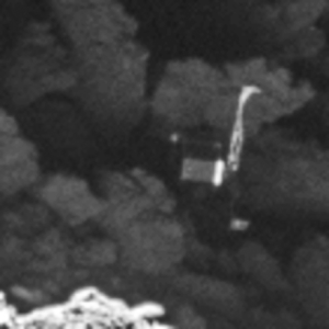
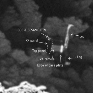
On 2 September 2016, the ESA team managing the Rosetta mission found Philae in photographs taken from the Rosetta spacecraft at an altitude of about 2.7 km (1.7 miles) above the surface of 67P. The photos show that Philae, which is about the size of a washing machine, is lying on its side, wedged among large rocks. Knowing Philae’s actual orientation and environment is expected to help ESA reevaluate the data Philae transmitted from its resting place.

Philae is the “poster child” for the hazards of landing on microgravity worlds.

Philae_close-up_node_full_image_2Philae’s final resting place on comet 67P. Source: ESAPhilae_close-up_labelled_node_full_image_2Annotated Philae photo. Source: ESA

Meanwhile, Rosetta is being maneuvered into ever-closer orbits around 67P, with the goal be taking measurements of the comet’s “atmosphere” very close to the surface. The Rosetta mission is expected to come to an end in September 2016 with the spacecraft colliding with 67P.

Exploring Microgravity Worlds

Peter Lobner

1.  Background:

We’re all familiar with scenes of the Apollo astronauts bounding across the lunar surface in the low gravity on the Moon, where gravity (g) is 0.17 of the gravity on the Earth’s surface. Driving the Apollo lunar rover kicked up some dust, but otherwise proved to be a practical means of transportation on the Moon’s surface. While the Moon’s gravity is low relative to Earth, techniques for achieving lunar orbit have been demonstrated by many spacecraft, many soft landings have been made, locomotion on the Moon’s surface with wheeled vehicles has worked well, and there is no risk of flying off into space by accidentally exceeding the Moon’s escape velocity.

There are many small bodies in the Solar System (i.e., dwarf planets, asteroids, comets) where gravity is so low that it creates unique problems for visiting spacecraft and future astronauts: For example:

  • Spacecraft require efficient propulsion systems and precise navigation along complex trajectories to rendezvous with the small body and then move into a station-keeping position or establish a stable orbit around the body.
  • Landers require precise navigation to avoid hazards on the surface of the body (i.e., craters, boulders, steep slopes), land gently in a specific safe area, and not rebound back into space after touching down.
  • Rovers require a locomotion system that is adapted to the specific terrain and microgravity conditions of the body and allows the rover vehicle to move across the surface of the body without risk of being launched back into space by reaction forces.
  • Many asteroids and comets are irregularly shaped bodies, so the surface gravity vector will vary significantly depending on where you are relative to the center of mass of the body.

You will find a long list of known objects in the Solar System, including many with diameters less than 1 km (0.62 mile), at the following link:

https://en.wikipedia.org/wiki/List_of_Solar_System_objects_by_size

You can determine the gravity on the surface of a body in the Solar System using the following equation:

Equation for g

where (using metric):

g = acceleration due to gravity on the surface of the body (m/sec2)

G = universal gravitational constant = 6.672 x 10⁻¹¹ m3/kg/sec2

M = mass of the body (kg)

r = radius of the body (which is assumed to be spherical) (m)

You can determine the escape velocity from a body using the following equation:

Equation - Escape velocity

Applying these equations to the Earth and several smaller bodies in in the Solar System yields the following results:
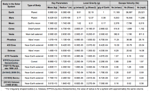
g and escape velocity table

Note how weak the gravity is on the small bodies in this table. These are very different conditions than on the surface of the Moon or Mars where the low gravity still allows relatively conventional locomotion.

As noted in my 31 December 2015 post, the “U.S. Commercial Space Launch Competitiveness Act,” which was signed into law on 25 November 2015, opens the way for U.S. commercial exploitation of space, including commercial missions to asteroids and comets.  Let’s take a look at missions to these microgravity worlds and some of the unique issues associated with visiting a microgravity world.

2.  Recent and Current Missions to Asteroids and Comets

There have been several spacecraft that have made a successful rendezvous with one or more small bodies in the Solar System. Several have been fly-by missions. Four spacecraft have flown in close formation with or entered orbit around low-gravity bodies. Three of these missions included landing on (or at least touching) the body, and one returned very small samples to Earth. These missions are:

  • National Aeronautics and Space Administration’s (NASA) NEAR-Shoemaker
  • Japan Aerospace Exploration Agency’s (JAXA) Hayabusa
  • European Space Agency’s (ESA) Rosetta
  • NASA’s Dawn

In addition, China’s Chang’e 2 mission demonstrated its ability to navigate to an asteroid intercept after completing its primary mission in lunar orbit. JAXA’s Hayabusa 2 mission currently is enroute to asteroid rendezvous.

Following is a short synopsis of each of these missions.

NASA’s NEAR-Shoemaker Mission (1996 – 2001): This mission was launched 17 February 1996 and on 27 June 1997 flew by the asteroid 253 Mathilde at a distance of about 1,200 km (746 miles).   On 14 February 2000, the spacecraft reached its destination and entered a near-circular orbit around the asteroid 433 Eros, which is about the size of Manhattan. After completing its survey of Eros, the NEAR spacecraft was maneuvered close to the surface and it touched down on 12 February 2001, after a four-hour descent, during which it transmitted 69 close-up images of the surface. Transmissions continued for a short time after landing. NEAR-Shoemaker was the first man-made object to soft-land on an asteroid.
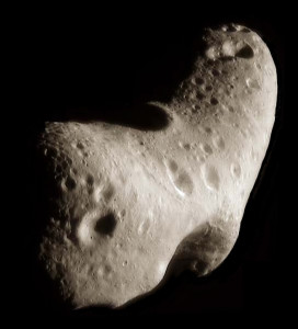
Asteroid Eros                Asteroid EROS. Source: NASA/JPL/JHUAPL

JAXA’s Hayabusa Mission (2003 – 2010): The Hayabusa spacecraft was launched in May 2003. This solar-powered, ion-driven spacecraft rendezvoused with near-Earth asteroid 25143 Itokawa in mid-September 2005.
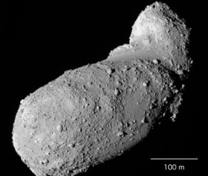
Asteroid Itokawa           Asteroid Itokawa. Source: JAXA

Hayabusa carried the solar-powered MINERVA (Micro/Nano Experimental Robot Vehicle for Asteroid) mini-lander, which was designed to be released close to the asteroid, land softly, and move across the surface using an internal flywheel and braking system to generate the momentum needed to hop in microgravity. However, MINERVA was not captured by the asteroid’s gravity after being released and was lost in deep space.

In November 2005, Hayabusa moved in from its station-keeping position and briefly touched the asteroid to collect surface samples in the form of tiny grains of asteroid material.
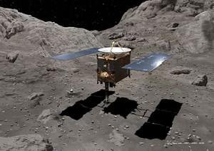
Hayabusa taking a sampleHayabusa in position to obtain samples. Source: JAXA

The spacecraft then backed off and navigated back to Earth using its failing ion thrusters. Hayabusa returned to Earth on 13 June 2010 and the sample-return capsule, with about 1,500 grains of asteroid material, was recovered after landing in the Woomera Test Range in the western Australian desert.

You’ll find a JAXA mission summary briefing at the following link:

https://www.nasa.gov/pdf/474206main_Kuninaka_HayabusaStatus_ExploreNOW.pdf

ESA’s Rosetta Mission (2004 – present): The Rosetta spacecraft was launched in March 2004 and in August 2014 rendezvoused with and achieved orbit around irregularly shaped comet 67P/Churyumov-Gerasimenko. This comet orbits the Sun outside of Earth’s orbit, between 1.24 and 5.68 AU (astronomical units; 1 AU = average distance from Earth’s orbit to the Sun). The size of 67P/Churyumov-Gerasimenko is compared to downtown Los Angeles in the following figure.
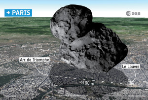
ESA Attempts To Land Probe On CometSource: ESA

Currently, Rosetta remains in orbit around this comet. The lander, Philae, is on the surface after a dramatic rebounding landing on 12 November 2014. Anchoring devices failed to secure Philae after its initial touchdown. The lander bounced twice and finally came to rest in an unfavorable position after contacting the surface a third time, about two hours after the initial touchdown. Philae was the first vehicle to land on a comet and it briefly transmitted data back from the surface of the comet in November 2014 and again in June – July 2015.

NASA’s Dawn Mission (2007 – present): Dawn was launched on 27 September 2007 and used its ion engine to fly a complex flight path to a 2009 gravitational assist flyby of Mars and then a rendezvous with the large asteroid Vesta (2011 – 2012) in the main asteroid belt.
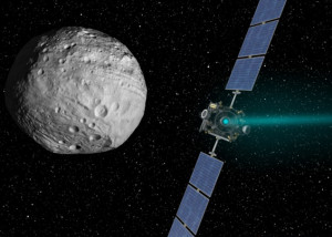
NASA_Dawn_spacecraft_near_Ceres   Dawn approaches Vesta. Source: NASA / JPL Caltech

Dawn spent 14 months in orbit surveying Vesta before departing to its next destination, the dwarf planet Ceres, which also is in the main asteroid belt. On 6 March 2015 Dawn was captured by Ceres’ gravity and entered its initial orbit following the complex trajectory shown in the following diagram.
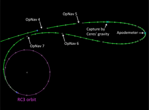
Dawn navigation to Ceres orbit   Dawn captured by Ceres gravity. Source: NASA / JPL Caltech

Dawn is continuing its mapping mission in a circular orbit at an altitude of 385 km (240 miles), circling Ceres every 5.4 hours at an orbital velocity of about 983 kph (611 mph). The Dawn mission does not include a lander.

See my 20 March 2015 and 13 Sep 2015 posts for more information on the Dawn mission.

CNSA’s Chang’e 2 extended mission (2010 – present): The China National Space Agency’s (CNSA) Chang’e 2 spacecraft was launched in October 2010 and placed into a 100 km lunar orbit with the primary objective of mapping the lunar surface. After completing this objective in 2011, Chang’e 2 navigated to the Earth-Sun L2 Lagrange point, which is a million miles from Earth in the opposite direction of the Sun. In April 2012, Chang’e 2 departed L2 for an extended mission to asteroid 4179 Toutatis, which it flew by in December 2012.
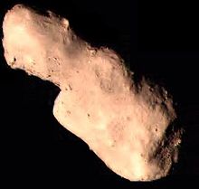
Toutatis_from_Chang'e_2Asteroid Toutatis. Source: CHSA

JAXA’s Hayabusa 2 Mission (2014 – 2020): The JAXA Hayabusa 2 spacecraft was launched on 3 December 2014. This ion-propelled spacecraft is very similar to the first Hayabusa spacecraft. Its planned arrival date at the target asteroid, 1999 JU3 (Ryugu), is in mid-2018.   As you can see in the following diagram, 1999 JU3 is a substantially larger asteroid than Itokawa.
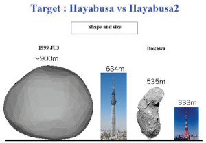
Hayabusa 1-2 target comparisonSource: JAXA

The spacecraft will spend about a year mapping the asteroid using Near Infrared Spectrometer (NIRS3) and Thermal Infrared Imager (TIR) instruments.

Hayabusa 2 includes three solar-powered MINERVA-II mini-landers and one battery-powered MASCOT (Mobile Asteroid Surface Scout) small lander. All landers will be deployed to the asteroid surface from an altitude of about 100 meters (328 feet) so they can be captured by the asteroid’s very weak gravity. The 1.6 – 2.5 kg (3.5 – 5.5 pounds) MINERVA-II landers will deliver imagery and temperature measurements. The 10 kg (22 pound) MASCOT will make measurements of surface composition and properties using a camera, magnetometer, radiometer, and infrared microscope. All landers are expected to make several hops to take measurements at different locations on the asteroid’s surface.
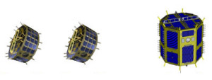
Three MINERVA landers

Three MINERVA mini-landers. Source: JAXA
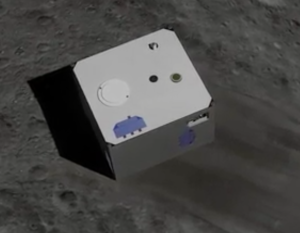
MASCOT lander         MASCOT small lander. Source: JAXA

For sample collection, Hayabusa 2 will descend to the surface to capture samples of the surface material. A device called a Small Carry-on Impactor (SCI) will be deployed and should impact the surface at about 2 km/sec, creating a small crater to expose material beneath the asteroid’s surface. Hayabusa 2 will attempt to gather a sample of the exposed material. More information about SCI is available at the following link:

http://www.lpi.usra.edu/meetings/lpsc2013/pdf/1904.pdf

At the end of 2019, Hayabusa 2 is scheduled to depart asteroid 1999 JU3 (Ryugu) and return to Earth in 2020 with the collected samples. You will find more information on the Hayabusa 2 mission at the JAXA website at the following links:

http://global.jaxa.jp/projects/sat/hayabusa2/

and,

http://www.lpi.usra.edu/sbag/meetings/jan2013/presentations/sbag8_presentations/TUES_0900_Hayabusa-2.pdf

3.  Future Missions:

NASA OSIRIS-REx: This NASA’s mission is expected to launch in September 2016, travel to the near-Earth asteroid 101955 Bennu, map the surface, harvest a sample of surface material, and return the samples to Earth for study. After arriving at Bennu in 2018, the solar-powered OSIRIS-Rex spacecraft will map the asteroid surface from a station-keeping distance of about 5 km (3.1 miles) using two primary mapping instruments: the OVIRS Visible and Infrared Spectrometer and the OTRS Thermal Emission Spectrometer. Together, these instruments are expected to develop a comprehensive map of Bennu’s mineralogical and molecular components and enable mission planners to target the specific site(s) to be sampled. In 2019, a robotic arm on OSIRIS-REx will collect surface samples during one or more very close approaches, without landing. These samples (60 grams minimum) will be loaded into a small capsule that is scheduled to return to Earth in 2023.
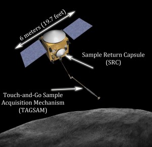
OSIRIS-REx SpacecraftOSIRIS-REx spacecraft. Source: NASA / ASU

For more information on OSIRIS-REx, visit the NASA website at the following link:

http://sservi.nasa.gov/articles/nasas-asteroid-sample-return-mission-moves-into-development/

and the ASU website at the following link:

http://www.asteroidmission.org/objectives/

NASA Asteroid Redirect Mission (ARM): This mission will involve rendezvousing with a near-Earth asteroid, mapping the surface for about a year, and locating a suitable bolder to be captured [maximum diameter about 4 meters (13.1 feet)]. The ARM spacecraft will land and capture the intended bolder, lift off and deliver the bolder into a stable lunar orbit during the first half of the next decade. The current reference target is known as asteroid 2008 EV5.
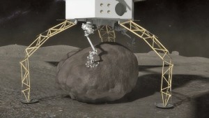
ARM asteroid-capture      ARM lander gripping a bolder on an asteroid. Source: NASA

You can find more information on the NASA Asteroid Redirect Mission at the following links:

https://www.nasa.gov/content/what-is-nasa-s-asteroid-redirect-mission

and

https://www.nasa.gov/pdf/756122main_Asteroid%20Redirect%20Mission%20Reference%20Concept%20Description.pdf

4. Locomotion in Microgravity

OK, you’ve landed on a small asteroid, your spacecraft has anchored itself to the surface and now you want to go out and explore the surface. If this is asteroid 2008 EV5, the local gravity is about 1.79 E-05 that of Earth (less than 2/100,000 the gravity of Earth) and the escape velocity is about 0.6 mph (1 kph). Just how are you going to move about on the surface and not launch yourself on an escape trajectory into deep space?

There is a good article on the problems of locomotion in microgravity in a 7 March 2015 article entitled, “A Lightness of Being,” in the Economist magazine. You can find this article on the Economist website at the following link:

http://www.economist.com/news/technology-quarterly/21645508-space-vehicles-can-operate-ultra-low-gravity-asteroids-and-comets-are

In this article, it is noted that:

“Wheeled and tracked rovers could probably be made to work in gravity as low as a hundredth of that on Earth……But in the far weaker microgravity of small bodies like asteroids and comets, they would fail to get a grip in fine regolith. Wheels also might hover above the ground, spinning hopelessly and using up power. So an entirely different system of locomotion is needed for rovers operating in a microgravity.”

Novel concepts for locomotion in microgravity include:

  • Hoppers / tumblers
  • Structurally compliant rollers
  • Grippers

Hoppers / tumblers: Hoppers are designed to move across a surface using a moving internal mass that can be controlled to transfer momentum to the body of the rover to cause it to tumble or to generate a more dramatic hop, which is a short ballistic trajectory in microgravity. The magnitude of the hop must be controlled so the lander does not exceed escape velocity during a hop. JAXA’s MINERVA-II and MASCOT asteroid landers both are hoppers.

JAXA described the MINERVA-II hopping mechanism as follows:

“MINERVA can hop from one location to another using two DC motors – the first serving as a torquer, rotating an internal mass that leads to a resulting force, sufficient to make the rover hop for several meters. The second motor rotates the table on which the torquer is placed in order to control the direction of the hop. The rover reaches a top speed of 9 centimeters per second, allowing it to hop a considerable distance.”
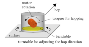
JAXA MINERVA hopperMINERVA torque & turntable. Source: JAXA

The MASCOT hopper operates on a different principle:

“With a mass of not even half a gram in the gravitational field of the asteroid, the (MASCOT) lander can easily withstand its initial contact with the surface and several bounces that are expected upon landing. It also means that only small forces are needed to move the lander from point to point. MASCOT’s Mobility System essentially consists of an off-centered mass installed on an eccentric arm that moves that mass to generate momentum that is sufficient to either rotate the lander to face the surface with its instruments or initiate a hop of up to 70 meters to get to the next sampling site.”
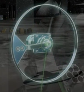
MASCOT Mobility SystemMASCOT mobility mechanism. Source: JAXA

You will find a good animation of MASCOT and its Mobility System at the following link:

http://www.dlr.de/dlr/en/desktopdefault.aspx/tabid-10081/151_read-18664/#/gallery/23722

NASA is examining a class of microgravity rovers called “hedgehogs” that are designed to hop and tumble on microgravity surfaces by spinning and braking a set of three internal flywheels. Cushions or spikes at the corners of the cubic body of a hedgehog protect the body from the terrain and act as feet while hopping and tumbling.
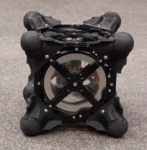
NASA Hedgehog                               NASA Hedgehog prototype. Source: NASA

Read more on the NASA hedgehog rovers at the following link:

http://www.jpl.nasa.gov/news/news.php?feature=4712

Structurally compliant rollers: One means of “rolling” across a microgravity surface is with a deformable structure that allows the location of the center of mass to be controlled in a way that causes the rover to tip over in the desired direction of motion. NASA is exploring the use of a class of rolling rovers called Super Ball Bots, which are terrestrial rovers based on a R. Buckminster Fuller’s tensegrity toy. NASA explains:

“The Super Ball Bot has a sphere-like matrix of cables and joints that could withstand being dropped from a spacecraft high above a planetary surface and hit the ground with a bounce. Once on the planet, the joints could adjust to roll the bot in any direction while housing a data collecting device within its core.”
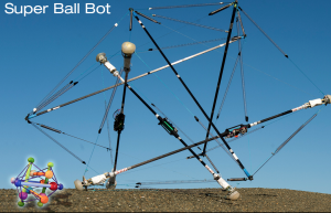
NASA Super Ball Bot                    Source: http://www.nasa.gov/content/super-ball-bot

You’ll find a detailed description of the principles behind tensegrity (tensional integrity) in a 1961 R. Buckminster Fuller paper at the following link:

http://www.rwgrayprojects.com/rbfnotes/fpapers/tensegrity/tenseg01.html

Grippers: Without having a grip on a microgravity body, a rover cannot use sampling tools that generate a reaction force on the rover (i.e., drills, grinders, chippers). For such operations to be successful a rover needs an anchoring system to secure the rover and transfer the reaction loads into the microgravity body.

An approach being developed by Jet Propulsion Laboratory (JPL) involves articulated feet with microspine grippers that have a large number of small claws that can grip irregular rocky surfaces.

JPL microspine gripper           Microspine gripper. Source: NASA / JPL

Such a gripper could be used to hold a rover in place during mechanical sampling activities or to allow a rover to climb across an irregular surface like a spider.  See more about the operation of the NASA / JPL microspine gripper at the following link:

https://www-robotics.jpl.nasa.gov/tasks/taskVideo.cfm?TaskID=206&tdaID=700015&Video=147

5. Conclusions

Missions to small bodies in our Solar System are very complex undertakings that require very advanced technologies in many areas, including: propulsion, navigation, autonomous controls, remote sensing, and locomotion in microgravity. The ambitious current and planned future missions will greatly expand our knowledge of these small bodies and the engineering required to operate spacecraft in their vicinity and on their surface.

While commercial exploitation of dwarf planets, asteroids and comets still may sound like science fiction, the technical foundation for such activities is being developed now. It’s hard to guess how much progress will be made in the next decades. However, I’m convinced that the “U.S. Commercial Space Launch Competitiveness Act,” will encourage commercial investments in space exploration and exploitation and lead to much greater progress than if we depended on NASA alone.

The technologies being developed also may lead, in the long term, to effective techniques for redirecting an asteroid or comet that poses a threat to Earth. Such a development would give our Planetary Defense Officer (see my 21 January 2016 post) an actual tool for defending the planet.
Lunar Lander XCHALLENGE and Lunar XPrize are Paving the way for Commercial Lunar Missions

Peter Lobner

Lunar Lander XCHALLENGE and Lunar XPrize are two competitions promoting the development of technologies, vehicles and systems by private firms for landing unmanned vehicles on the Moon and demonstrating functional capabilities that can support future lunar exploration missions. The legal and regulatory framework for U.S. commercial space activities was greatly simplified in November 2015, when the Commercial Space Launch Competitiveness Act was signed into law. See my 31 December 2015 post for details on this Act.

On 3 August 2016, Lunar XPrize competitor Moon Express became the first private enterprise to be licensed by the U.S. Government (the Federal Aviation Administration) to conduct a mission to the lunar surface. Other Lunar XPrize competitors also are seeking similar approvals in preparation for lunar missions before the end of 2017.

Let’s take a look at how the private sector got this far.

Northrop Grumman / NASA Lunar Lander XCHALLENGE

In October 2007, XPrize and Northrop Grumman, in partnership with NASA’s Centennial Challenges program, launched the $2 million Lunar Lander XCHALLENGE, in which competing teams designed small rocket vehicles capable of routine and safe vertical takeoff and landing for lunar exploration and other applications. You’ll find details on the Lunar Lander XChallenge at the following link and an overview in the following text:

http://lunarlander.xprize.org

Lunar Lander XCHALLENGE badge   Source: XPrize

The XCHALLENGE was divided into two levels.

Level 1:

  • Required a rocket to take off from a designated launch area; climb to a low, fixed altitude of about 50 meters (164 feet); and fly for at least 90 seconds while translating horizontally to a precise landing point on a different landing pad 100 meters (328 feet) from the launch point. The flight must be repeated in reverse within a two and a half hour period.
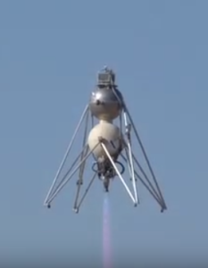
  • Armadillo Aerospace, of Mesquite, TX won the $350K Level 1 first prize in October 2008. Masten Space Systems of Mojave, CA won the $150K Level 1 second place prize on 7 October 2009 when their Xombie rocket completed its flight with an average landing accuracy of 6.3 inches (16 cm).
  • You can watch a short video on the 2008 Level 1 competition and Armadillo Aerospace’s winning Level 1 flight at the following link:

https://www.youtube.com/watch?v=IhnY5tT4YeE

Armadillo Level 1 winner Armadillo Aerospace Level 1 winner. Source: NASA

Level 2:

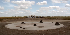
  • Similar to the Level 1 flight profile, but required the rocket to fly for 180 seconds before landing precisely on a simulated lunar surface constructed with craters and boulders 100 meters (328 feet) from the launch point. The minimum flight time was calculated so that the Level 2 mission closely simulated the power needed to perform a real descent from lunar orbit down to the surface of the Moon.

XCHALLENGE lunar landing siteLevel 2 landing site. Source: NASA

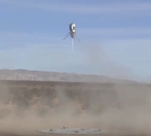
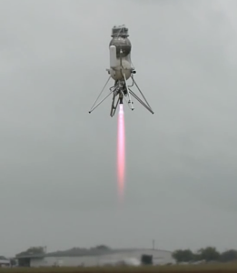
  • Masten Space Systems won the $1M Level 2 first prize with the flight of their Xoie rocket on 30 October 2009. Xoie completed its Level 2 flight with an average landing accuracy of about 7.5 inches (19 cm). Armadillo Aerospace took second place and a $500K prize with the 12 September 2009 flight of their Scorpius (Super-mod) rocket, which had an average landing accuracy of about 34 inches (89 cm). These prizes were awarded on 5 November 2009 in Washington D.C.

Xoie winning Level 2 flightMasten Aerospace Xoie: Level 2 winner. Source: NASA.

  • You can watch a short video summary on the XCHALLENGE results, including the winning flight by Xoie at the following link:

https://www.youtube.com/watch?v=MAvZxa1VXKI

Armadillo Scorpius Level 2Armadillo Aerospace’s Scorpius: Level 2 second place. Source: NASA

  • You can watch a short video on the Scorpius 2009 flight at the following link:

https://www.youtube.com/watch?v=ALKvai4p7OE

The other XCHALLENGE competitors, TrueZer0 and Unreasonable Rockets, failed to qualify for Level 1 or 2.

Google Lunar XPrize

The Google Lunar XPrize was created in 2007, overlapping with the Northrop Grumman / NASA Lunar Lander XCHALLENGE. The Lunar XPrize is intended to actually deliver payloads to the Moon and “incentivize space entrepreneurs to create a new era of affordable access to the Moon and beyond.” The motto for the Google XPrize is: “Back to the Moon for good.”

The basic mission requirements are:

  • Land a privately funded rover on the Moon at a site announced in advance.
  • Travel at least 500 meters along a deliberate path on the lunar surface.
  • Transmit two “Mooncasts” from the surface of the Moon, including specified types of videos and still images.
  • Receive specified data uplinks from Earth and re-transmit the data back to Earth.
  • Deliver a small payload provided by XPrize (not to exceed 500 grams).
  • Private funding for 90% of the total mission cost. No more than 10% government funding, including the value of in-kind support.
  • Launch contract in place by the end of 2016 and mission completion by the end of 2017.

The primary incentives are large financial award to the first and second teams that accomplish all of the mission requirements: $20 million Grand Prize and $5 million for second place. In addition, there are several other financial prizes that add up to total awards of more than $40 million. Of course, the winner will have bragging rights for a long time to come.

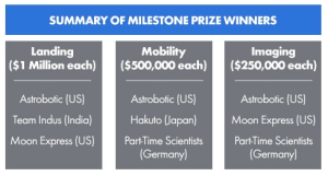
  • Milestone prizes: $5.25 million already has been awarded to teams that demonstrated robust hardware in three categories: landing, mobility, and imaging. The following Milestone prize winners have been announced:

Milestone prize winnersSource: XPrize

  • Bonus prizes: Up to $4 million for successfully completing additional scientific and technical tasks not in the mission requirements
  • Apollo Heritage Bonus Prize: $4 million for making an Apollo Heritage Mooncast from the site of an Apollo moon landing.
  • Heritage Bonus Prize: $1 million for making a Mooncast from another site of interest to XPrize.
  • Range Bonus Prize: $2 million for a rover that can traverse five kilometers on the Moon’s surface.
  • Survival Bonus Prize: $2 million for successfully operating on two separate lunar days.
  • Water Detection Bonus Prize: $4 million for producing scientifically conclusive proof of the presence of water on the Moon.

The Google Lunar XPrize home page is at the following link, where you can navigate to many details on this competition and sign up for an XPrize newsletter:

http://lunar.xprize.org

The Google Lunar XPrize began with 29 teams and now 16 remain. As noted above, five teams already have won Milestone prizes.

The three teams that competed in the landing milestone competition are taking different approaches. Astrobotics is using a lunar lander developed by Masten Aerospace. Indus and Moon Express are developing their own lunar landers.

So far, only two teams have launch contracts:

  • On 7 October 2015, the Israeli team SpaceIL became the first Lunar XPrize team to sign a launch contract. They signed a launch services contract with Spaceflight Industries for launch on a SpaceX Falcon 9 launcher in the second half of 2017.
  • On 8 December 2017, XPrize verified the Moon Express launch contract with Rocket Lab USA. Moon Express contracted for three launches using an Electron booster, which, as of mid-2016, is still being developed.

By the end of 2016, all competitors that intend to continue into the finals must have a launch contract in place.

So far, only three nations have made a soft landing on the Moon: USA, Russia and China. In 2017, a privately funded team may be added to that list.  That would be a paradigm shift for lunar exploration, opening the door for private teams and commercial firms to have regular, relatively low cost access to the Moon.

Update 23 December 2016: Google Lunar XPrize Status

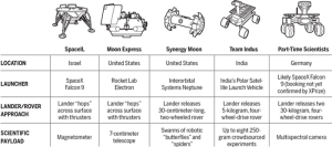
On 22 December 2016, author Daniel Clery posted an article, “Here’s who could win the $20 million XPrize for roving on the moon—but will any science get done?” The author reports that six teams claim to have booked flights to the moon for their lunar landers / rovers. The following chart provides a summary for five of the competitors. The small (4 kg) rover for the sixth competitor, Japan’s Team Hakuto, will be delivered to the moon on the same lander as India’s Team Indus.

LunarXPrixe competitors Dec 2016

Click on the graphic above to enlarge. Source: G. Grullón/Science

As I noted previously, all competitors that intend to continue into the Lunar XPrize finals must have a launch contract in place by the end of 2016, and the mission to the moon must be completed by the end of 2017.

You can read Daniel Clery’s complete article on the Sciencemag.org website, at the following link:

http://www.sciencemag.org/news/2016/12/heres-who-could-win-20-million-xprize-roving-moon-will-any-science-get-done?utm_campaign=news_daily_2016-12-22&et_rid=215579562&et_cid=1068715

Update 23 January 2018: Google Lunar XPrize Competion Cancelled

After concluding that none of the remaining competitors could meet the extended 31 March 2018 deadline for landing on the Moon, this competition came to a close, with the $30M in prizes remaining unclaimed.

Where Earth-orbiting Satellites go to Die

Updated 30 April 2020

Peter Lobner

For satellites large enough to generate reentry debris that can reach the surface of the Earth, there are four choices: Manitowoc, WI, the Spacecraft Cemetery, a Graveyard Orbit, or the Space Garbage Truck. Let’s look at these alternatives.

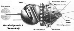
Korabi-Sputnik 1 (aka Sputnik 4) was launched by the Soviet Union on 15 May 1960 and was reported to be a test of an orbital spacecraft with a recoverable, pressurized capsule capable of carrying a cosmonaut. At the time of its launch, Sputnik 4 was the largest satellite placed in orbit, with a weight of at least 5 tons.

Koralb_sputnikSource: pics-about-space.com

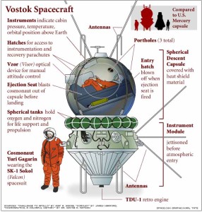
Sputnik 4 appears to have been a prototype of the Soviet Vostok spacecraft that carried the first human, Yuri Gagarin, into orbit on 12 April 1961.

Vostok_diagram Source: Space.com, graphics by Karl Tate

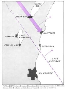
Due to a failure in the control or reentry system, the Sputnik 4 capsule did not return to Earth as planned, but instead, remained in orbit until 5 September 1962. On that day, Sputnik 4 reentered the Earth’s atmosphere and broke up, with fragments landing in Lake Michigan and in downtown Manitowoc, WI. The following diagram from the 3 December 1962 issue of Aviation Week magazine shows the paths for Sputnik 4 fragments that landed on the main street of Manitowoc, Wisconsin.

Sputnik 4 reentry over Manitowoc_5

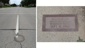
On a recent trip, I visited the site in Manitowoc where a large, hot fragment landed and embedded itself into the asphalt pavement of a main street. That site is commemorated by a brass ring in the street and a granite plaque on the sidewalk.

Sputnik 4 landed hereSource: Author’s photos 

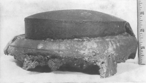
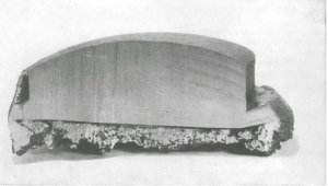
The Sputnik 4 debris was analyzed by the U.S. and then returned to the Soviet Union. The following photos from the 3 December 1962 issue of Aviation Week magazine show details of the largest fragment.

Sputnik 4 fragment photo 1

Sputnik 4 fragment photo 2

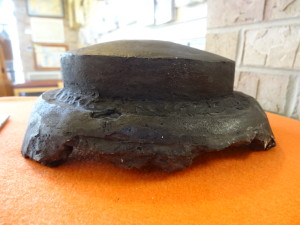
The Smithsonian Institution made two reproductions of this large fragment. Today, both reproductions normally are in Manitowoc; one at the Rahr-West Art Museum (on loan to a Green Bay museum on the day of my visit) and the other at the Manitowoc Visitor’s Center. Here’s a photo of the reproduction at the Visitor’s Center.

Sputnik 4 fragment DSC03294Source: Author’s photo

You can read more about Sputnik 4 in the article, “Sputnik Crashed Here,” at the following link:

http://www.roadsideamerica.com/story/12959

Many small satellites have reentered the Earth’s atmosphere at end-of-life and burned up completely, without debris reaching the Earth’s surface. No special end-of-life procedures are needed to manage the retirement of such small satellites.

Today, there is a systematic process for de-orbiting larger satellites in low Earth orbit that can produce reentry debris capable of reaching the Earth’s surface. NASA reports:

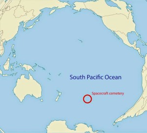
“There is a solution—spacecraft operators can plan for the final destination of their old satellites to make sure that any debris falls into a remote area. This place even has a nickname—the Spacecraft Cemetery! It’s in the Pacific Ocean and is pretty much the farthest place from any human civilization you can find.”

Spacecraft-cemeterySource: NASA

NASA has developed plans for de-orbiting the >500 ton International Space Station (ISS) at the end of its operational life, which is expected to last until at least 2028. There also is a plan to de-orbit the ISS if it must be evacuated in an emergency and cannot be recovered. You’ll find more information on NASA’s plans at the following link:

https://www.nasaspaceflight.com/2013/08/bringing-down-iss-plans-stations-demise-updated/

When the time comes, ISS reentry will be targeted for the Spacecraft Cemetery.

Spacecraft in higher orbits, including geosynchronous orbit, commonly are maneuvered into “graveyard orbits” where they are retired, outside the orbits of other active satellites. Here they will remain for a very long time without significant risk of interfering with active satellites or de-orbiting in an uncontrolled reentry.  

An example is the Lincoln Experimental Satellite 5 (LES-5), which was developed by the MIT Lincoln Laboratory and launched into synchronous orbit in 1967 to test satellite-based ultra-high frequency (UHF) secure communications for US military users.  The solar-powered LES-5 remained active until May 1971 after which it was decommissioned and moved to a higher graveyard orbit in 1972.  On 24 March 2020, Scott Tilley, an amateur radio operator living in British Columbia, announced that he had located a signal from the LES-5 satellite at 237 MHz, transmitting at about 100 bits/sec from its graveyard orbit.  You’ll find more details on the “re-discovery” of LES-5 here:

https://www.popularmechanics.com/space/satellites/a32293223/les-5-satellite/

A new option is under development by the European Space Agency (ESA), which launched the Clean Space Initiative in 2013 to address the great amount of debris and dead satellites in Earth orbit.  ESA reported:

“Scientists estimate the total number of space debris objects in orbit to be around 29 000 for sizes larger than 10 cm, 670 000 larger than 1 cm, and more than 170 million larger than 1 mm.

Any of these objects can cause harm to an operational satellite. For example, a collision with a 10 cm object would entail a catastrophic fragmentation of a typical satellite, a 1 cm object will most likely disable a spacecraft and penetrate the International Space Station shields, and a 1 mm object could destroy subsystems. Scientists generally agree that, for typical satellites, a collision with an energy-to-mass ratio exceeding 40 J/g would be catastrophic.”

The ESA’s warning signs posted in orbit proved to be ineffective.

No littering in orbit  Source:  How-to Geek Newsletter

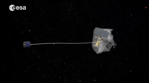
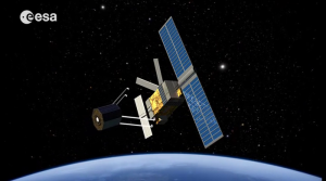
Therefore, ESA is planning a more ambitious mission called e.DeOrbit for removing space debris.  For its demonstration mission, the ESA e.DeOrbit spacecraft is being designed to capture debris in polar orbit between 800 – 1,000 km (497 – 621 miles) altitude. Various concepts are being considered to capture the intended orbital target, including nets, arms, and tentacles. Once captured, the e.DeOrbit spacecraft will maneuver the combined satellite (target + e.DeOrbit) into a controlled reentry. The first launch of an e.DeOrbit garbage truck is expected to be in the 2023 time frame.

ESA eDeOrbit nete.DeOrbit capture using a net. Source: ESA
ESA eDeOrbit armse.DeOrbit capture using arms. Source: ESA
You can read more on the ESA Clean Space Initiative and the e.DeOrbit mission at the following links:
http://www.esa.int/Our_Activities/Space_Engineering_Technology/Clean_Space/How_to_catch_a_satellite

and

http://iaassconference2013.space-safety.org/wp-content/uploads/sites/28/2013/06/1200_Biesbroek_Innocenti.pdf

NASA’s Valkyrie (R5) Humanoid Robot is Being Groomed to Support Future Space Exploration Missions

Peter Lobner

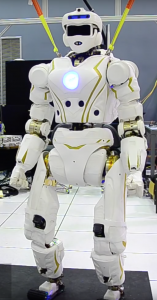
The design of National Aeronautics and Space Administration’s (NASA’s) humanoid robot R5, commonly known as Valkyrie, started in October 2012 and it was unveiled in December 2013.

NASA Valkyrie robot  Source: NASA

Valkyrie was developed by a team from NASA’s Johnson Space Center (JSC) in Houston, in partnership with the University of Texas and Texas A&M and with funding from the state of Texas to compete in the Defense Advanced Projects Research Agency’s (DARPA) Robotics Challenge (DRC).  You’ll find a technical description of Valkyrie on the IEEE Spectrum website at the following link:

http://spectrum.ieee.org/automaton/robotics/military-robots/nasa-jsc-unveils-valkyrie-drc-robot

In the 2013 DRC Trials Valkyrie was a Track A entry, but it failed to score any points, largely due to unforeseen data communications problems.  An assessment of the developmental and operational problems encountered during the 2013 DRC Trials and another assessment of Valkyrie by the Florida Institute for Human & Machine Cognition (IHMC) is reported on the IEEE Spectrum website at the following link:

http://spectrum.ieee.org/automaton/robotics/humanoids/update-nasa-valkyrie-robot

Valkyrie did not compete in the 5 – 6 June 2015 DRC Finals. Instead, NASA brought two Valkyrie robots to the DRC Finals for display and demonstration and to help promote NASA’s Space Robotics Challenge (SRC), which was announced in March 2015.

NASA describes the SRC as follows:

“The Space Robotics Challenge is currently contemplated as a dual level, two-track challenge. The Level I challenge would involve a virtual challenge competition in software simulation and the Level II demonstration challenge would involve use of software to control a robot to perform sequences of tasks. Both Levels of the challenge would have a Track A and Track B option. A competitor would pick only one track in which to compete. Track A would utilize the Robonaut 2 platform and focus on simulated in-space tasks such as spacecraft maintenance and operations in transit to Mars, while Track B would utilize the R5 platform robot to perform simulated tasks on planetary surfaces, such as precursor habitat deployment on Mars, or disaster relief in an industrial setting on Earth.”

The highest scoring teams from the Level I (simulation) challenge will be given access to NASA-provided robots to prepare for the Level II (physical) challenge.

You can download a NASA Fact Sheet on SRC at the following link:

https://www.nasa.gov/sites/default/files/atoms/files/fs_space_robotics_150908.pdf

As part of SRC, NASA awarded Valkyrie robots to two university groups that competed in the DRC Finals. The winners announced in November 2015 were:

  • A team at MIT under the leadership of Russ Tedrake. Team MIT placed 6th in the 2015 DRC Finals with an Atlas robot built by Boston Dynamics
  • A team at Northeastern University under the leadership of Taskin Padir, who formerly was Co-PI of the Worcester Polytechnic Institute (WPI) – Carnegie Mellon University (CMU) team that placed 7th in the DRC Finals with an upgraded Atlas robot known as Warner.

Each team has possession of a Valkyrie robot for two years; receives up to $250,000; and has access to onsite and virtual technical support from NASA. NASA stated that, “The robots will have walking, balancing and manipulating capabilities so that future research may focus on the development of complex behaviors that would advance autonomy for bipedal humanoid robots.” These two teams will not compete in the SRC Level I challenge, but will be eligible to compete in the Level II challenge.

An assessment of Valkyrie’s potential roles in future missions to Mars was published in 23 June 2015 on the IEEE Spectrum website. You can read this article at the following link:

http://spectrum.ieee.org/automaton/robotics/humanoids/nasa-wants-help-training-valkyrie-robot-to-go-to-mars

The types of activities a humanoid robot might perform on a Mars mission are expected to become tasks to be demonstrated by each team choosing Track B in the SRC.

In the time between the DRC Finals and the SRC Level II competitions, I’m sure we’ll see substantial improvements in humanoid robot performance.

Landing a Reusable Booster Rocket on a Dime

Updated 18 March 2020

Peter Lobner

There are two U.S. firms that have succeeded in launching and recovering a booster rocket that was designed to be reusable. These firms are Jeff Bezos’ Blue Origin and Elon Musk’s SpaceX.   Their booster rockets are designed for very different missions.

  • Blue Origin’s New Shepard booster and capsule are intended for brief, suborbital flights for space tourism and scientific research. The booster and capsule will be “man-rated” for passenger-carrying suborbital missions.
  • In contrast, SpaceX’s Falcon 9 booster rocket is designed to deliver a variety of payloads to Earth orbit. The payload may be the SpaceX Dragon capsule or a different civilian or military spacecraft. Currently, the Falcon 9 booster and Dragon capsule are not “man-rated” for orbital missions. SpaceX is developing a crewed version of the Dragon capsule that, in the future, will be used to deliver and return crewmembers for the International Space Station (ISS).

Both firms cite a cost advantage of recovering and reusing an expensive booster rocket and space capsule. Let’s see how they’re doing.

Blue Origin

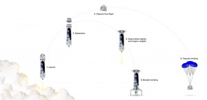
The basic flight profiles of a single-stage, single engine New Shepard booster and capsule are shown in the following diagram. The primary goals of each flight are to boost the capsule and passengers above 62.1 miles (100 km), safely recover the capsule and passengers, and safely recover the booster rocket. You can see in the diagram that the booster rocket and the capsule separate after the booster’s rocket engine is shutdown and they are recovered separately. At separation, the booster and capsule are traveling at about Mach 3 (about 1,980 mph, 3,186 kph). The orientation of the booster rocket is controlled during descent and the rocket engine is restarted once at low altitude to bring the booster to a soft, vertical landing. Both the booster rocket and the capsule are designed for reuse.

Blue-origin-flight-profileSource: Blue Origin

On 23 November 2015, Blue Origin made history when, on its first attempt, the New Shepard booster completed a suborbital flight that culminated with the autonomous landing of the booster rocket near the launch site in west Texas. The capsule landed nearby under parachutes. You can view a video of this historic flight at the following link:

https://www.youtube.com/watch?v=9pillaOxGCo

This same New Shepard booster was launched again on 22 January 2016, completed the planned suborbital flight, and again made an autonomous safe landing. This flight marked the first reuse of a booster rocket.

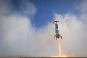
Again using the same hardware, New Shepard was launched on its third flight and safely recovered on 2 April 2016. On this flight, the rocket engine was re-started at a lower altitude (3,635 feet, 1,107 m) than on the previous flights to demonstrate the fast startup of the engine. The booster rocket made an on-target landing, touching down at a velocity of 4.8 mph (7.7 kph).

New Shepard landing 3Source: Blue Origin

You can view a short video of the third New Shepard flight at the following link:

https://www.blueorigin.com/news/news/pushing-the-envelope#youtubeYU3J-jKb75g

In this video, the view from the capsule at 64.6 miles (104 km) above the Earth is stunning. As the landing of the booster rocket approaches, it is dropping like a stone until the rocket engine powers up, quickly stops the descent, and brings the booster rocket in for an accurate, soft, vertical landing.

So, the current score for Blue Origin is 3 attempts and 3 successful soft, vertical landings in less than 5 months. The same New Shepard booster was used all three times (i.e., it has been reused twice).

Refer to the Blue Origin website at the following link for more information.

https://www.blueorigin.com

SpaceX Falcon 9 (F9R)

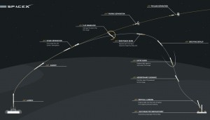
The basic flight profile for a two-stage Falcon 9 recoverable booster on an orbital mission is shown in the following diagram. For ISS re-supply missions, the target for the Dragon capsule is in a near-circular orbit at an altitude of about 250 miles (403 km) and an orbital velocity of about 17,136 mph (27,578 kph). The first stage shuts down and separates from the second stage at an altitude of about 62.1 miles (100 km) and a speed of about 4,600 mph (7,400 kph, Mach 7). These parameters are for illustrative purposes only and will vary as needed to meet the particular mission requirements. The second stage continues into orbit with a Dragon capsule or other payload.

The nine-engine first stage carries extra fuel to enable some of the booster rockets to re-start three times after stage separation to adjust trajectory, decelerate, and make a soft vertical landing on an autonomous recovery barge floating in the ocean 200 miles (320 km) or more downrange from the launch site.

The empty weight of the recoverable version of the Falcon 9 first stage (the F9R) is 56,438 pounds (25,600 kg,), which is about 5,511 pounds (2,500 kg) more than the basic, non-recoverable version (V1.1). The added fuel and structural weight to enable recovery of the first stage reduces the payload mass that can be delivered to orbit.

Falcon flight profile to barge landingSource: SpaceX

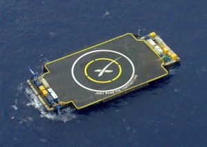
The autonomous “drone” barge is a very small target measuring about 170 ft. × 300 ft. (52 m × 91 m). It is equipped with azimuthal thrusters that provide precise positioning using GPS position data. The Falcon 9 booster knows where the drone barge should be. The Falcon 9’s four landing legs span 60 ft. (18 m), and all must land on the barge.

SpaceX_ASDSSource: SpaceX

SpaceX made a series of unsuccessful attempts to land on a drone barge before their first successful landing:

  • 10 January 2015: First attempt; hard landing; booster destroyed.
  • 11 February 2015: High seas prevented use of the barge. Instead, the Falcon 9 first stage was flown to a soft, vertical landing in the ocean, simulating a barge landing.
  • 14 April 2015: Second attempt; successful vertical landing but the booster toppled, likely due to remaining lateral momentum.
  • 7 January 2016: Third attempt; successful vertical landing but the booster toppled, likely due to a mechanical failure in one landing leg.
  • 4 March 2016: Fourth attempt, with low fuel reserve and using only three engines; hard landing; booster destroyed.

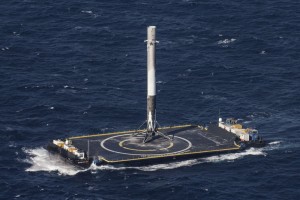
On 8 April 2016, a Falcon 9 booster was launched from Cape Canaveral on an ISS re-supply mission. The first stage of this booster rocket became the first to make a successful landing on the drone barge downrange in the Atlantic.

A002_C002_0408A9Source: SpaceX

You can view a short video of the Falcon 9 booster landing on the drone barge at the following link:

https://www.youtube.com/watch?v=RPGUQySBikQ

In the video, you will note the barge heaving in the moderate seas. After landing, the 156 foot (47.5 m) tall booster rocket is just balanced on its landing legs. Before the barge can be towed back to port, crew must board the barge and secure the booster. This is done by placing “shoes” over the landing feet and welding the shoes to the deck of the barge. Once back at Cape Canaveral, the booster will be examined and the rocket engine will be test fired to determine if the first stage can be reused.

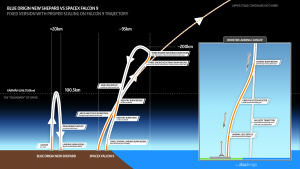
Previously, on 21 December 2015, SpaceX successfully launched its Falcon 9 booster on an orbital mission and then landed the first stage back on the ground at Cape Canaveral. As shown in the diagram below, this involved a very different flight profile than for a Falcon 9 flight with a landing on the downrange drone barge. For the December 2015 flight, the Falcon 9 first stage had to reverse direction to fly back to Cape Canaveral from about 59 miles (95 km) downrange and then decelerate and maneuver for a soft, vertical landing about 10 minutes after launch.

Blue Origin-Falcon flight profile comparedSource: SpaceX

After recovering the booster, the Falcon 9 was inspected and the engines were successfully re-tested on 15 January 2016, on a launch pad at Cape Canaveral. I could not determine if this Falcon 9 first stage has been reused.

So, the current score for SpaceX is 6 attempts (not counting the February 2015 soft landing in the ocean) and 2 successes (one on land and one on the drone barge) in 15 months.

Refer to the SpaceX website at the following link for more information.

http://www.spacex.com

The bottom line

In the above diagram for the December 2015 Falcon 9 flight, the relative complexity of a typical New Shepard flight profile and the Falcon 9 flight profile with return to Cape Canaveral is clear. The Falcon 9 flight profile for a landing on the small, moving, down-range drone barge is even more complex.

The New Shepard sub-orbital mission is much less challenging than any Falcon 9 orbital mission. Nonetheless, both booster rockets face very similar challenges as they approach the landing site to execute an autonomous, soft, vertical landing.

Both Blue Origin and SpaceX have made tremendous technological leaps in demonstrating that a booster rocket can make an autonomous, soft, vertical landing and remain in a condition that allows its reuse in a subsequent mission. Blue Origin actually has reused their booster rocket and capsule twice, further demonstrating the maturity of reusable rocket technology.

It remains to be seen if this technology actually delivers the operating cost savings anticipated by Blue Origin and SpaceX. I hope it does. When space tourism becomes a reality, the hoped-for cost benefits of reusable booster rockets and spacecraft could affect my ticket price.

18 March 2020 Update:  Four years later

On 6 March 2020, SpaceX launched its 20th commercial resupply services mission (CRS-20) to the International Space Station (ISS).  The successful launch concluded with the 50thsuccessful landing of the first stage of a Falcon 9 launch vehicle.  On this mission, the first stage flew back for a landing at Cape Canaveral in the windiest conditions encountered to date, 25 to 30 mph.  This was the last launch with the original cargo-only version of the Dragon capsule. Subsequent launches will use 2nd-generation Dragon capsules that are roomier and designed to also accommodate astronauts.

About two weeks later, on 18 March 2020, SpaceX launched another successful Falcon 9 mission, for the first time using a first stage that had flown on four prior missions.  The satellite payload was launched into the intended orbit.  However, a malfunction in one of nine first stage engines prevented recovery of the booster rocket.

On 11 December 2019, Blue Origin reported that New Shepard mission NS-12 was successfully completed.  “This was the 6th flight for this particular New Shepard vehicle. Blue Origin has so far reused two boosters five times each consecutively, so today marks a record with this booster completing its 6th flight to space and back.”

Booster reusability has become a reality for SpaceX and Blue Origin, and other firms are following their lead by developing new reusable launch vehicles.  These are encouraging steps toward more economic access to Earth orbit and beyond.  Both SpaceX and Blue Origin have advanced reusable launch vehicle technology significantly in the past four years.  Both soon will begin human space flight using their respective launch vehicles and space capsules.

Synthetic Aperture Radar (SAR) and Inverse SAR (ISAR) Enable an Amazing Range of Remote Sensing Applications

Peter Lobner

SAR Basics

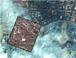
Synthetic Aperture Radar (SAR) is an imaging radar that operates at microwave frequencies and can “see” through clouds, smoke and foliage to reveal detailed images of the surface below in all weather conditions. Below is a SAR image superimposed on an optical image with clouds, showing how a SAR image can reveal surface details that cannot be seen in the optical image.

Example SAR imageSource: Cassidian radar, Eurimage optical

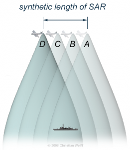
SAR systems usually are carried on airborne or space-based platforms, including manned aircraft, drones, and military and civilian satellites. Doppler shifts from the motion of the radar relative to the ground are used to electronically synthesize a longer antenna, where the synthetic length (L) of the aperture is equal to: L = v x t, where “v” is the relative velocity of the platform and “t” is the time period of observation. Depending on the altitude of the platform, “L” can be quite long. The time-multiplexed return signals from the radar antenna are electronically recombined to produce the desired images in real-time or post-processed later.

SAR principle

Source: Christian Wolff, http://www.radartutorial.eu/20.airborne/pic/sar_principle.print.png

This principle of SAR operation was first identified in 1951 by Carl Wiley and patented in 1954 as “Simultaneous Buildup Doppler.”

SAR Applications

There are many SAR applications, so I’ll just highlight a few.

Boeing E-8 JSTARS: The Joint Surveillance Target Attack Radar System is an airborne battle management, command and control, intelligence, surveillance and reconnaissance platform, the prototypes of which were first deployed by the U.S. Air Force during the 1991 Gulf War (Operation Desert Storm). The E-8 platform is a modified Boeing 707 with a 27 foot (8 meter) long, canoe-shaped radome under the forward fuselage that houses a 24 foot (7.3 meters) long, side-looking, multi-mode, phased array antenna that includes a SAR mode of operation. The USAF reports that this radar has a field of view of up to 120-degrees, covering nearly 19,305 square miles (50,000 square kilometers).

E-8 JSTARSSource: USAF

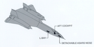
Lockheed SR-71: This Mach 3 high-altitude reconnaissance jet carried the Advanced Synthetic Aperture Radar System (ASARS-1) in its nose. ASARS-1 had a claimed 1 inch resolution in spot mode at a range of 25 to 85 nautical miles either side of the flight path.  This SAR also could map 20 to 100 nautical mile swaths on either side of the aircraft with lesser resolution.

SR-71Source: http://www.wvi.com/~sr71webmaster/sr_sensors_pg2.htm

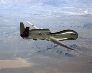
Northrop RQ-4 Global Hawk: This is a large, multi-purpose, unmanned aerial vehicle (UAV) that can simultaneously carry out electro-optical, infrared, and synthetic aperture radar surveillance as well as high and low band signal intelligence gathering.

Global HawkSource: USAF

Below is a representative RQ-4 2-D SAR image that has been highlighted to show passable and impassable roads after severe hurricane damage in Haiti. This is an example of how SAR data can be used to support emergency management.

Global Hawk Haiti post-hurricane image123-F-0000X-103Source: USAF

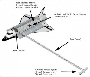
NASA Space Shuttle: The Shuttle Radar Topography Mission (SRTM) used the Space-borne Imaging Radar (SIR-C) and X-Band Synthetic Aperture Radar (X-SAR) to map 140 mile (225 kilometer) wide swaths, imaging most of Earth’s land surface between 60 degrees north and 56 degrees south latitude. Radar antennae were mounted in the Space Shuttle’s cargo bay, and at the end of a deployable 60 meter mast that formed a long-baseline interferometer. The interferometric SAR data was used to generate very accurate 3-D surface profile maps of the terrain.

Shuttle STRMSource: NASA / Jet Propulsion Laboratory

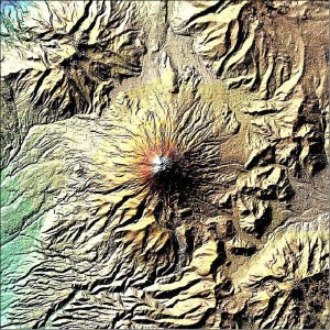
An example of SRTM image quality is shown in the following X-SAR false-color digital elevation map of Mt. Cotopaxi in Ecuador.

Shuttle STRM imageSource: NASA / Jet Propulsion Laboratory

You can find more information on SRTM at the following link:

https://directory.eoportal.org/web/eoportal/satellite-missions/s/srtm

ESA’s Sentinel satellites: Refer to my 4 May 2015 post, “What Satellite Data Tell Us About the Earthquake in Nepal,” for information on how the European Space Agency (ESA) assisted earthquake response by rapidly generating a post-earthquake 3-D ground displacement map of Nepal using SAR data from multiple orbits (i.e., pre- and post-earthquake) of the Sentinel-1A satellite.  You can find more information on the ESA Sentinel SAR platform at the following link:
http://www.esa.int/Our_Activities/Observing_the_Earth/Copernicus/Sentinel-1/Introducing_Sentinel-1

You will find more general information on space-based SAR remote sensing applications, including many high-resolution images, in a 2013 European Space Agency (ESA) presentation, “Synthetic Aperture Radar (SAR): Principles and Applications”, by Alberto Moreira, at the following link:

https://earth.esa.int/documents/10174/642943/6-LTC2013-SAR-Moreira.pdf

ISAR Basics

ISAR technology uses the relative movement of the target rather than the emitter to create the synthetic aperture. The ISAR antenna can be mounted in a airborne platform. Alternatively, ISAR also can be used by one or more ground-based antennae to generate a 2-D or 3-D radar image of an object moving within the field of view.

ISAR Applications

Maritime surveillance: Maritime surveillance aircraft commonly use ISAR systems to detect, image and classify surface ships and other objects in all weather conditions. Because of different radar reflection characteristics of the sea, the hull, superstructure, and masts as the vessel moves on the surface of the sea, vessels usually stand out in ISAR images. There can be enough radar information derived from ship motion, including pitching and rolling, to allow the ISAR operator to manually or automatically determine the type of vessel being observed. The U.S. Navy’s new P-8 Poseidon patrol aircraft carry the AN/APY-10 multi-mode radar system that includes both SAR and ISAR modes of operation.

The principles behind ship classification is described in detail in the 1993 MIT paper, “An Automatic Ship Classification System for ISAR Imagery,” by M. Menon, E. Boudreau and P. Kolodzy, which you can download at the following link:

https://www.ll.mit.edu/publications/journal/pdf/vol06_no2/6.2.4.shipclassification.pdf

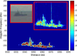
You can see in the following example ISAR image of a vessel at sea that vessel classification may not be obvious to the casual observer. I can see that an automated vessel classification system is very useful.

Ship ISAR image

Source: Blanco-del-Campo, A. et al., http://ieeexplore.ieee.org/xpl/login.jsp?tp=&arnumber=5595482&url=http%3A%2F%2Fieeexplore.ieee.org%2Fiel5%2F7361%2F5638351%2F05595482.pdf%3Farnumber%3D5595482

Imaging Objects in Space: Another ISAR (also called “delayed Doppler”) application is the use of one or more large radio telescopes to generate radar images of objects in space at very long ranges. The process for accomplishing this was described in a 1960 MIT Lincoln Laboratory paper, “Signal Processing for Radar Astronomy,” by R. Price and P.E. Green.

Currently, there are two powerful ground-based radars in the world capable of investigating solar system objects: the National Aeronautics and Space Administration (NASA) Goldstone Solar System Radar (GSSR) in California and the National Science Foundation (NSF) Arecibo Observatory in Puerto Rico. News releases on China’s new FAST radio telescope have not revealed if it also will be able to operate as a planetary radar (see my 18 February 2016 post).

The 230 foot (70 meter) GSSR has an 8.6 GHz (X-band) radar transmitter powered by two 250 kW klystrons. You can find details on GSSR and the techniques used for imaging space objects in the article, “Goldstone Solar System Radar Observatory: Earth-Based Planetary Mission Support and Unique Science Results,” which you can download at the following link:

http://echo.jpl.nasa.gov/asteroids/Slade_Benner_Silva_IEEE_Proceedings.pdf

The 1,000 foot (305 meter) Arecibo Observatory has a 2.38 GHz (S-band) radar transmitter, originally rated at 420 kW when it was installed in 1974, and upgraded in 1997 to 1 MW along with other significant upgrades to improve radio telescope and planetary radar performance. You will find details on the design and upgrades of Arecibo at the following link:

http://www.astro.wisc.edu/~sstanimi/Students/daltschuler_2.pdf

The following examples demonstrate the capabilities of Arecibo Observatory to image small bodies in the solar system.

  • In 1999, this radar imaged the Near-Earth Asteroid 1999 JM 8 at a distance of about 5.6 million miles (9 million km) from Earth. The ISAR images of this 1.9 mile 3-km) sized object had a resolution of about 49 feet (15 meters).
  • In November 1999, Arecibo Observatory imaged the tumbling Main-Belt Asteroid 216 Kleopatra. The resulting ISAR images, which made the cover of Science magazine, showed a dumbbell-shaped object with an approximate length of 134.8 miles (217 kilometers) and varying diameters up to 58.4 miles (94 kilometers).

Asteroid image  Source: Science

More details on the use of Arecibo Observatory to image planets and other bodies in the solar system can be found at the following link:

http://www.naic.edu/general/index.php?option=com_content&view=article&id=139&Itemid=474

The NASA / Jet Propulsion Laboratory Asteroid Radar Research website also contains information on the use of radar to map asteroids and includes many examples of asteroid radar images. Access this website at the following link:
http://echo.jpl.nasa.gov

Miniaturization

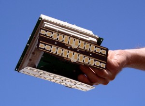
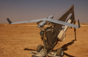
In recent years, SAR units have become smaller and more capable as hardware is miniaturized and better integrated. For example, Utah-based Barnard Microsystems offers a miniature SAR for use in lightweight UAVs such as the Boeing ScanEagle. The firm claimed that their two-pound “NanoSAR” radar, shown below, weighed one-tenth as much as the smallest standard SAR (typically 30 – 200 pounds; 13.6 – 90.7 kg) at the time it was announced in March 2008. Because of power limits dictated by the radar circuit boards and power supply limitations on small UAVs, the NanoSAR has a relatively short range and is intended for tactical use on UAVs flying at a typical ScanEagle UAV operational altitude of about 16,000 feet.

Barnard NanoSARSource: Barnard Microsystems

ScanEagle_UAVScanEagle UAV. Source: U.S. Marine Corps.

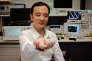
Nanyang Technological University, Singapore (NTU Singapore) recently announced that its scientists had developed a miniaturized SAR on a chip, which will allow SAR systems to be made a hundred times smaller than current ones.

?????????????????????????????????????????????????????????Source: NTU

NTU reports:

“The single-chip SAR transmitter/receiver is less than 10 sq. mm (0.015 sq. in.) in size, uses less than 200 milliwatts of electrical power and has a resolution of 20 cm (8 in.) or better. When packaged into a 3 X 4 X 5-cm (0.9 X 1.2 X 1.5 in.) module, the system weighs less than 100 grams (3.5 oz.), making it suitable for use in micro-UAVs and small satellites.”

NTU estimates that it will be 3 to 6 years before the chip is ready for commercial use. You can read the 29 February 2016 press release from NTU at the following link:

http://media.ntu.edu.sg/NewsReleases/Pages/newsdetail.aspx?news=c7aa67e7-c5ab-43ae-bbb3-b9105a0cd880

With such a small and hopefully low cost SAR that can be integrated with low-cost UAVs, I’m sure we’ll soon see many new and useful radar imaging applications.

Remarkable Multispectral View of Our Milky Way Galaxy

Peter Lobner, updated 18 August 2023

Moody Blues cover - In search of the lost chordAlbum Album cover art credit: Deram Records

Some of you may recall the following lyrics from the 1968 Moody Blues song, “The Word,” by Graeme, Edge, from the album “In Search of the Lost Chord”:

This garden universe vibrates complete

Some, we get a sound so sweet

 Vibrations reach on up to become light

And then through gamma, out of sight

Between the eyes and ears there lie

The sounds of color and the light of a sigh

And to hear the sun, what a thing to believe

But it’s all around if we could but perceive

 To know ultraviolet, infrared and X-rays

Beauty to find in so many ways

On 24 February 2016, the European Southern Observatory (ESO) Consortium announced that it has completed the ATLASGAL Survey of the Milky Way. The survey mapped the entire galactic plane visible from the southern hemisphere at sub-millimeter wavelengths, between infrared light and radio waves, using the Atacama Pathfinder EXperiment (APEX) telescope located at 5,100 meters (16,732 ft.) above sea level in Chile’s Atacama region. The southern sky is particularly important because it includes the galactic center of our Milky Way. The Milky Way in the northern sky has already been mapped by the James Clerk Maxwell Telescope, which is a sub-millimeter wavelength telescope at the Mauna Kea Observatory in Hawaii.

The new ATLASGAL maps cover an area of sky 140 degrees long and 3 degrees wide. ESO stated that these are the sharpest maps yet made, and they complement those from other land-based and space-based observatories. The principal space-based observatories are the following:

  • European Space Agency’s (ESA) Plank satellite: Mission on-going, mapping anisotropies of the cosmic microwave background at microwave and infrared frequencies.
  • ESA’s Herschel Space Observatory: Mission on-going, conducting sky surveys in the far-infrared and sub-millimeter frequencies.
  • National Aeronautics and Space Administration (NASA) Spitzer Space Telescope: Mission on-going, conducting infrared observations and mapping as described in my 1 April 2015 post.
  • NASA’s Hubble Space Telescope: Mission on-going, observing and mapping at ultraviolet, optical, and infrared frequencies.
  • NASA’s Chandra X-Ray Observatory: Mission on-going, observing and mapping X-ray sources.
  • NASA’s Compton Gamma Ray Observatory: Mission ended in 2000. Observed and mapped gamma ray and x-ray sources.

ESO reported that the combination of Planck and APEX data allowed astronomers to detect emission spread over a larger area of sky and to estimate from it the fraction of dense gas in the inner galaxy. The ATLASGAL data were also used to create a complete census of cold and massive clouds where new generations of stars are forming.

You can read the ESO press release at the following link:

https://www.eso.org/public/news/eso1606/

Below is a composite ESO photograph that shows the same central region of the Milky Way observed at different wavelengths.

ESO Multispectral view of Milky WaySource: ESO/ATLASGAL consortium/NASA/GLIMPSE consortium/VVV Survey/ESA/Planck/D. Minniti/S. Guisard. Acknowledgement: Ignacio Toledo, Martin Kornmesser

  • The top panel shows compact sources of sub-millimeter radiation detected by APEX as part of the ATLASGAL survey, combined with complementary data from ESA’s Planck satellite, to capture more extended features.
  • The second panel shows the same region as seen in shorter, infrared wavelengths by the NASA Spitzer Space Telescope
  • The third panel shows the same part of sky again at even shorter wavelengths, the near-infrared, as seen by ESO’s VISTA infrared survey telescope at the Paranal Observatory in Chile. Regions appearing as dark dust tendrils in the third panel show up brightly in the ATLASGAL view (top panel).
  • The bottom panel shows the more familiar view in visible light, where most of the more distant structures are hidden from view

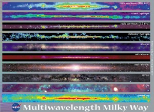
NASA’s Goddard Space Flight Center also  created a multispectral view of the Milky Way, which  is shown in the following composite photograph of the same central region of the Milky Way observed at different wavelengths.

NASA Goddard multispectralSource: NASA Goddard Space Flight Center

Starting from the top, the ten panels in the NASA image cover the following wavelengths.

  • Radio frequency (408 MHz)
  • Atomic hydrogen
  • Radio frequency (2.5 GHz)
  • Molecular hydrogen
  • Infrared
  • Mid-infrared
  • Near-infrared
  • Optical
  • X-ray
  • Gamma ray

The Moody Blues song, “The Word,” ends with the following lyrics:

 Two notes of the chord, that’s our full scope

But to reach the chord is our life’s hope

And to name the chord is important to some

So they give it a word, and the word is “Om”

While “Om” (pronounced or hummed “ahh-ummmm”) traditionally is a sacred mantra of Hindu, Jain and Buddhist religions, it also may be the mantra of astronomers as they unravel new secrets of the Milky Way and, more broadly, the Universe. I suspect that completing the ATLASGAL Survey of the Milky Way was an “Om” moment for the many participants in the ESO Consortium effort.

For more information

Virgin Galactic’s SpaceShipTwo is a Step Closer to Operational Commercial Spaceflights from Spaceport America

Peter Lobner

In my 13 April 2015 post, I provided an introduction to three U.S. commercial, suborbital human spaceflight programs. You may recall that Virgin Galactic’s first SpaceShipTwo was destroyed in an in-flight accident on 31 October 2014. The in-flight breakup of SpaceShipTwo resulted from the premature unlocking of the wing, which allowed the wing to move to the high-drag “feathered” position while the ship was accelerating through the transonic region (i.e., not yet supersonic). The pilot was seriously injured and the copilot was killed in this accident. You can find the Executive Summary of the National Transportation Safety Board’s (NTSB’s) accident report at the following link:

http://www.ntsb.gov/investigations/AccidentReports/Pages/AAR1502.aspx

More information from the 28 July 2015 NTSB Board meeting is available at the following link:

http://www.ntsb.gov/news/events/Pages/2015_spaceship2_BMG.aspx

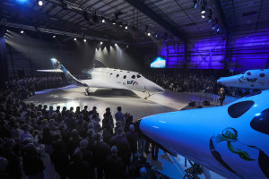
Today, Virgin Galactic unveiled the second SpaceShipTwo at the Mojave Air and Space Port in California. The ship was named, Virgin Spaceship (VSS) Unity by Professor Stephen Hawking, who said in a recorded speech, “I would be very proud to fly on this spaceship.”

VSS_Unity_Reveal Source: Virgin Galactic

The second SpaceShipTwo, which was under construction before the crash of its predecessor, is very similar to the first article, but with the following significant changes:

  • Feathering system: Virgin Galactic reports, “With regard to the accident specifically, we have made one structural change to the vehicle, which is to add a mechanical inhibit to the featherlock system that would prevent that from ever being inadvertently opened at the wrong time in flight.”
  • Rocket fuel: Virgin Galactic switched from a hydroxyl-terminated polybutadiene (HTBP) rubber-based solid fuel to a polyamide (plastic)-based fuel for the rocket motor on the first SpaceShipTwo. For the second SpaceShipTwo, Virgin Galactic announced in October 2015 that it was switching back to HTBP-based fuel.

Virgin Galactic has not yet announced other design and/or operational changes.

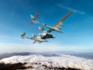
Like the first SpaceShipTwo, VSS Unity will go through an extensive test program that starts with “captive carry” flights on the WhiteKnightTwo aircraft.

SpaceShipTwo carriedWhiteKnightTwo carrying SpaceShipTwo; source: Virgin Galactic

The next series of tests include unpowered (gliding) flights after being dropped from WhiteKnightTwo, and finally, powered tests that will validate the flight envelope of SpaceShipTwo. At the conclusion of this testing program, VSS Unity may become the first commercial space vehicle to make regular, suborbital flights with paying passengers.

You can keep track of the progress being made at the Virgin Galactic website at the following link:

http://www.virgingalactic.com

The commercial flights will be conducted from Spaceport America, which is located in the desert east of Truth of Consequences, NM. You can find information of the Spaceport and make arrangements for a tour at the following website.

http://spaceportamerica.com

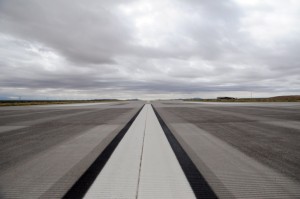
I visited Spaceport America in October 2015 and found it to be an impressive, but lonely facility, just waiting for the start of regular commercial space missions. The main hanger, shown below, housed only a SpaceShipTwo mockup and the enormous runway was silent.

All that will change after VSS Unity completes its test program and begins the operational phase of commercial human spaceflight in the desert of southern New Mexico. These are exciting times!

Spaceport pic 1

Spaceport pic 2

Spaceport pic 3Source, three photos: Author

Relax, the Planetary Defense Officer has the Watch

Peter Lobner

On 7 January 2016, NASA formalized its ongoing program for detecting and tracking Near-Earth Objects (NEOs) by establishing the Planetary Defense Coordination Office (PDCO). You can read the NASA announcement at the following link:

https://www.nasa.gov/feature/nasa-office-to-coordinate-asteroid-detection-hazard-mitigation

PDCO is responsible for supervision of all NASA-funded projects to find and characterize asteroids and comets that pass near Earth’s orbit around the sun. PDCO also will take a leading role in coordinating interagency and intergovernmental efforts in response to any potential impact threats. Specific assigned responsibilities are:

  • Ensuring the early detection of potentially hazardous objects (PHOs), which are defined as asteroids and comets whose orbits are predicted to bring them within 0.05 Astronomical Units (AUs) of Earth (7.48 million km, 4.65 million miles); and of a size large enough to reach Earth’s surface – that is, greater than 30 to 50 meters (98.4 to 164.0 feet);
  • Tracking and characterizing PHOs and issuing warnings about potential impacts;
  • Providing timely and accurate communications about PHOs; and
  • Performing as a lead coordination node in U.S. Government planning for response to an actual impact threat.

As you can see in the following organization chart, PDCO is part of NASA’s Planetary Science Division, in the agency’s Science Mission Directorate in Washington D.C.  PDCO is led by Lindley Johnson, longtime NEO program executive, who now has the very impressive title of “Planetary Defense Officer”.

Planetary Defense Coordination OfficeSource: NASA PDCO

You can find out more at the PDCO website at the following link:

https://www.nasa.gov/planetarydefense

The PDCO includes the Near Earth Object (NEO) Observation Program, which was established in 1998 in response to a request from the House Committee on Science that NASA find at least 90% of 1 km (0.62 mile) and larger NEOs. That goal was achieved by end of 2010.

The NASA Authorization Act of 2005 increased the scope of NEO objectives by amending the National Aeronautics and Space Act of 1958 (“NASA Charter”) by adding the following new functional requirement:

 ‘‘The Congress declares that the general welfare and security of the United States require that the unique competence of the National Aeronautics and Space Administration be directed to detecting, tracking, cataloging, and characterizing near-Earth asteroids and comets in order to provide warning and mitigation of the potential hazard of such near-Earth objects to the Earth.’’

 This was further clarified by stating that NASA will:

“…plan, develop, and implement a Near-Earth Object Survey program to detect, track, catalogue, and characterize the physical characteristics of near-Earth objects equal to or greater than 140 meters (459 feet) in diameter in order to assess the threat of such near-Earth objects to the Earth. It shall be the goal of the Survey program to achieve 90 percent completion of its near-Earth object catalog within fifteen years (by 2020)”

The contractors supporting the NASA NEO Observation Program are Jet propulsion Laboratory (JPL), Massachusetts Institute of Technology (MIT) / Lincoln laboratory, Smithsonian Astrophysical Observatory, University Space Research Association, University of Arizona, and University of Hawaii / Institute of Astronomy.

Once detected, NEO orbits are precisely predicted and monitored by the Center for NEO Studies (CNEOS) at JPL. Their website is at the following link:

http://neo.jpl.nasa.gov/neo/

The catalog of known NEOs as of 3 November 2015 included 13,206 objects. NASA reports that new NEOs are being identified at a rate of about 1,500 per year. Roughly half of the known NEOs – about 6,800 – are objects larger than 140 meters (459 feet) in diameter. The estimated population of NEOs of this size is about 25,000. Current surveys are finding NEOs of this size at a rate of about 500 per year.  Recent encounters with NEOs include:

  • Asteroid 2015 TB145, the “Halloween Pumpkin”
    • Roughly spherical, about 610 meters (2,000 feet) in diameter
    • Detected 10 October 2015, approaching from the outer solar system, 21 days before closest approach
    • Closest approach occurred on 31 October 2015 at a distance of 310,000 miles (1.3 times the distance to the Moon) at a speed of about 78,000 miles an hour.
  • Asteroid airburst near Chelyabinsk, Russia
    • Airburst occurred 15 February 2013
    • Object estimated to be about 19 meters in diameter
    • Approached from the inner solar system; not detected before airburst
    • Peter Brown at the University of Western Ontario, estimated the energy of the Chelyabinsk airbust at 400 to 600 kilotons of TNT.  You can read this analysis in at the following link:

http://www.nature.com/articles/nature12741.epdf?referrer_access_token=OvLha95ujqCh0k4maNPuFNRgN0jAjWel9jnR3ZoTv0PyqszVJsMboh07BaZDfmONEget5lbJtDTXTwE2VvrDWIEgk5iXkd1EFvngsntJFeC1wOg4ASyku1lPPrkWlAPvoRMkxnjovQe0UYqFmFkZ6v9qqq9DL9_3CwYPmTWA6e-sweRQPIyrDHMUaAQYWA9H4TNSsZGN662UcGxlW5d1GA%3D%3D&tracking_referrer=www.theguardian.com

Another result of the NEO Observation Program is the following map of data gathered from 1994-2013 on small asteroids impacting Earth’s atmosphere and disintegrating to create very bright meteors, technically called “bolides” and commonly referred to as “fireballs”.  Sizes of orange dots (daytime impacts) and blue dots (nighttime impacts) are proportional to the optical radiated energy of impacts measured in billions of Joules (GJ) of energy, and show the location of impacts from objects about 1 meter (3 feet) to almost 20 meters (60 feet) in size.  You can see a rather uniform distribution of these fireballs over the surface of the Earth.

bolide_events_1994-2013 Source: NASA NEO Observation Program

In September 2014, the NASA Inspector General published the report, “NASA’s Efforts to Identify Near-Earth Objects and Mitigate Hazards,” which you can download for free at the following link:

https://oig.nasa.gov/audits/reports/FY14/IG-14-030.pdf

Key findings were the following:

  • Even though the Program has discovered, categorized, and plotted the orbits of more than 11,000 NEOs since 1998, NASA will fall short of meeting the 2005 Authorization Act goal of finding 90 percent of NEOs larger than 140 meters (459 feet) in diameter by 2020.
  • ….we believe the Program would be more efficient, effective, and transparent were it organized and managed in accordance with standard NASA research program requirements

You will find an NEO Program update, including a reference to the new Planetary Defense Coordination Office, presented by Lindley Johnson on 8 November 2915 at the following link:

http://www.minorplanetcenter.net/IAWN/2015_national_harbor/NEO_Program_update.pdf

So, what will we see in the years ahead as technology is explored and techniques are developed to defend Earth against a significant NEO impact? There have been many movies that have tried to answer that question, but none offered a particularly good answer.

Asteroid movies 2Asteroid movies 1 Source: Google

In 1968, Star Trek explored this issue in Season 3, Episode 3, “The Paradise Syndrome”. Ancient aliens had left a planetary defense device to protect a primitive civilization against their equivalent of NEOs. Only the intervention of Capt. James T. Kirk restored the device to operation in time to deflect an incoming asteroid and save the indigenous civilization.

Star Trek - The Paradise Syndrome 1 Source: memory-alpha.wiki.comStar Trek - The Paradise Syndrome 2 Source: technovelgy.com

Our new Planetary Defense Officer has a comparable responsibility on Earth, but without the benefits of special effects.

In 2010, National Academies Press published, “Defending Planet Earth: Near-Earth Object Surveys and Hazard Mitigation Strategies.” This report explores civil defense mitigation action and three basic defense techniques:

  • Slow push-pull methods
  • Kinetic impact methods
  • Nuclear methods

If you have a MyNAP account, you can download this report for free at the following link:

http://www.nap.edu/catalog/12842/defending-planet-earth-near-earth-object-surveys-and-hazard-mitigation

NAP Defending Planet Earth Source: NAP