Category Archives: Spacecraft and Missions

Reusable Space Launch Vehicles are Becoming a Reality

Peter Lobner

In my 12 April 2016 post, “Landing a Reusable Booster Rocket on a Dime,” I discussed the first successful flights and recoveries of the SpaceX Falcon 9 orbital booster rocket and Blue Origin’s New Shepard suborbital booster rocket. In the past year, both SpaceX and Blue Origin have successfully launched and recovered several rockets. In addition, SpaceX and Blue Origin both have reused one or more booster rockets that were flown on previous missions.

Here’s a quick look at the SpaceX and Blue Origin track records and their future plans for even more ambitious recoverable launch vehicles. We’ll also take a brief look at what competitors are doing with their existing and planned launch vehicles.

SpaceX reusable booster rockets: Falcon 9 v1.2, Falcon Heavy, and Interplanetary Transport System

The Falcon 9 v1.2 is the current, operational version of this commercial, medium-lift, two-stage family of launch vehicles. This booster has a length of 230 ft (70 m) with the payload fairing and a booster diameter of 12 ft (3.66 m). The first stage generates 1.7 million pounds of thrust from seven Merlin engines burning liquid oxygen (LOX) and RP-1 kerosene. The second stage uses a single Merlin engine optimized for vacuum conditions. The Falcon 9 v1.2 specified payload mass is:

  • 50,265 pounds (22.8 metric tons, 22,800 kg) to Low Earth Orbit (LEO),
  • 18,298 pounds (8.3 metric tons, 8,300 kg) to Geosynchronous Transfer Orbit (GTO), or
  • 8,862 pounds (4.02 metric tons, 4,020 kg) to escape velocity.

Falcon Heavy is an advanced heavy-lift, two-stage launch vehicle with a first stage comprised of three Falcon 9 booster rockets. The first stage generates 5.1 million pounds of thrust from 21 Merlin engines. The Falcon Heavy specified payload mass is:

  • 119,931 pounds (54.4 metric tons, 54,400 kg) to LEO,
  • 48,942 pounds (22.2 metric tons, 22,200 kg) to GTO, or
  • 29,983 pounds (13.6 metric tons, 13,600) kg to escape velocity.

The first Falcon Heavy is expected to be launched in late 2017.

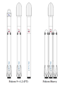
The Falcon 9 v1.2 family and the Falcon Heavy launch vehicles are shown in the following diagram. The scale-up from Falcon 9 V1.2 to Falcon Heavy is relatively straightforward. Versions designed for recovering the first stage include four extendable landing legs near the base of the rocket. In the diagram below, you can see that one version of the Falcon 9 does not include the landing legs, sacrificing booster recovery for greater booster performance.

  Source: SpaceX   

SpaceX describes their Falcon 9 booster recovery process as follows:

“After being jettisoned, the first stage (autonomously) initiates a flip maneuver and begins a powered return back to Earth. Using a combination of reaction control thrusters, forward-mounted grid fins, and thrust from one to three of the main engines, the first stage flies either to a remotely-operated ship in the Atlantic (or Pacific) Ocean, or to land. Upon arrival, the vehicle deploys a set of landing legs and sets itself down upright.”

In practice, SpaceX expects to recover about 1/3 of its boosters on land, back near the launch site. Boosters for most of the remaining missions (primarily the higher-energy missions) will be recovered on a downrange drone ship. You can watch a short video explaining these two mission profiles at the following link:

https://www.youtube.com/watch?v=lEr9cPpuAx8

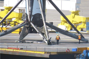
A recovered Falcon 9 first stage booster rocket is very large:

  • overall length of about 151 ft (46 m) in landing configuration,
  • dry mass is about 50,706 pounds (23,000 kg), and
  • estimated total mass is 94,578 pounds (42,900 kg) with 5% residual fuel after landing.

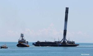
The large scale of the Falcon 9 booster is apparent in the following photo taken after a landing on the stationary drone ship.
Source: SpaceXSource: Ken Kremer/kenkremer.com

You can see a video of the January 2017 Falcon 9 v1.2 launch and booster recovery at the following link:

https://www.youtube.com/watch?v=c8wy5sQ2JDE

The SpaceX mission on 30 March 2017 marked two important milestones:

  • The first reuse of a Falcon 9 booster stage, which was recovered on the drone barge and will be available again for reuse.
  • The first recovery of the costly (about $6 million) payload fairing, which was jettisoned during ascent and returned under parachute for an ocean splashdown.  The payload fairing will be reused.

As of 3 April 2017, the SpaceX Falcon 9 scorecard is:

  • Thirteen booster recoveries attempted
  • Three successful recoveries on land; first in December 2015
  • Six successful recoveries on a drone ship at sea, first in April 2016
  • Four drone ship recovery failures
  • One booster stage reused

The number of times a Falcon 9 first stage can be re-flown is not clearly specified. However, Elon Musk placed that number at 10 – 20 additional missions, and, with minor refurbishment, up to 100 missions.

Falcon Heavy missions will involve considerably more complex, simultaneous, autonomous booster recovery operations. The port and starboard Falcon 9 boosters will separate first and fly to designated recovery points, likely on land. The core booster will burn longer before separating from the second stage, which will take the payload into orbit. After separation, the core Falcon 9 booster also will fly to a designated recovery point, likely on a downrange drone ship. After a Falcon Heavy launch, it literally will be raining Falcon 9 boosters. This will be a spectacular demonstration of autonomous flight control and range safety.

You’ll find a list of Falcon 9 and Falcon Heavy launches, booster recovery status, and future missions at the following link:

https://en.wikipedia.org/wiki/List_of_Falcon_9_and_Falcon_Heavy_launches

SpaceX has been developing the recoverable Dragon space capsule as a family of spacecraft to be launched by the Falcon booster to conduct a variety of orbital and interplanetary missions. Like the recoverable Falcon booster, the Dragon capsule uses aerodynamic forces to slow its descent into the atmosphere and rocket propulsion for the final landing phase.

  • Dragon CRS: Since October 2012, this unmanned cargo version of the Dragon space capsule has been conducting Commercial Resupply Service (CRS) missions to the International Space Station (ISS) and returning cargo to Earth.
  • Dragon CRS “free-flyer”: The Dragon capsule also can operate independently in Earth orbit carrying a variety of payloads and returning them to Earth.
  • Dragon 2: This is a human-rated version of the Dragon space capsule. The first manned orbital flight in expected 2018.
  • Red Dragon: This is an unmanned version of Dragon 2 adapted for a mission to Mars and launched by a Falcon Heavy. Red Dragon is designed to make a propulsive landing on Mars’ surface with a 2,200 pound (1,000 kg) payload. The first launch of a Red Dragon mission could occur as early as 2018. Thereafter, SpaceX plans to conduct “regular “ (as suitable launch windows occur) Red Dragon missions to Mars.

The SpaceX Interplanetary Transport System (ITS) is a concept for an enormous launch vehicle, a manned interplanetary spacecraft, and a tanker spacecraft for refueling the interplanetary spacecraft in Earth orbit before starting the interplanetary phase of the mission. ITS will enable transportation of a large crew and equipment to Mars starting in the late 2020s. Later, when propellant plants have been established on distant bodies in the solar system, the ITS interplanetary spacecraft will be able to refuel in deep space and journey beyond Mars. The ITS is “conceptualized to be fully reusable with 1,000 uses per booster, 100 uses per tanker and 12 round trips to Mars with one spacecraft over a period of over 25 years.”

As shown in the following diagram, the ITS booster rocket carrying the interplanetary spacecraft is much larger than the National Aeronautics and Space Administration’s (NASA) Saturn V used in the 1960s and 1970s on the Apollo lunar missions. At launch, the ITS will be 400 ft (122 m) tall and 39.4 ft (12 m) in diameter.
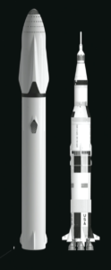
  ITS & Saturn V. Source: SpaceX

 With 42 Raptor sub-cooled liquid methane / liquid oxygen engines, the first stage will have a liftoff thrust of about 26 million pounds, which is more than three times the thrust of Saturn V. This engine configuration is reminiscent of the Soviet N-1 moon rocket, (circa late 1960s), which clustered 30 engines in a similar configuration.
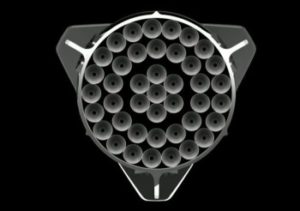
  ITS 1st stage Raptor engines. Source: SpaceX

The ITS specified payload mass is:

  • 1 million pounds (500 metric tons, 500,000 kg) to LEO with a fully expendable booster, or
  • 661,000 pounds (300 metric tons, 300,000 kg) to LEO with a reusable booster

ITS can lift ten times the payload of the Falcon Heavy booster.

The first stage of the ITS launch vehicle will be designed to fly back to the launch site for rapid servicing and reuse (i.e., to launch the refueling tanker spacecraft). In landing configuration, the ITS booster stage will be about 254 ft (77.5 m) long with a dry mass of about 275 tons (25 metric tons, 250,000 kg).

You can watch Elon Musk’s briefing on the ITS concept, including a short video of the ITS launch and interplanetary mission profile, at the following link.

http://www.spacex.com/mars

Can you spell A M B I T I O U S? The SpaceX ITS concept certainly is ambitious, but it offers a much more compelling vision of future manned spaceflight than anything NASA has offered over the past decade.

Blue Origin reusable booster rockets: New Shepard and New Glenn

New Shepard is a small, single stage, suborbital rocket intended for research and commercial passenger service to the fringe of space, above the Karman line at 62 miles (330,000 ft, 100 km) above the Earth. New Shepard is named for Project Mercury astronaut Alan Shepard, who, on 5 May 1961, made the first U.S. suborbital flight in the Freedom 7 capsule launched from Cape Canaveral by a Redstone rocket. The New Shepard, in launch and recovery configurations, is shown in the following figure.
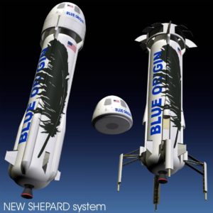
Source: https://www.stlfinder.com/3dmodels/Besos

You can see a short video showing the June 2016 fourth launch and recovery of the New Shepard booster and capsule at the following link:

https://www.youtube.com/watch?v=nNRs2gMyLLk

As of 3 April 2017, the New Shepard scorecard is:

  • Six booster recoveries attempted
  • Five successful recoveries on land; first in November 2015
  • One booster recovery failure
  • One booster stage recovered and used five times

In all of these New Shepard unmanned test flights, the passenger capsule was recovered.

Blue Origin expects to conduct the first manned tests of New Shepard in late 2017. Commercial passenger flights, with up to six people in the space capsule, could begin in 2018.  Blue Origin has stated that they may be able to conduct as many as 50 New Shepard flights per year.

You’ll find a list of New Shepard launches and booster recovery status, at the following link:

https://en.wikipedia.org/wiki/Blue_Origin

On 29 March 2017, the National Aeronautic Association (NAA) announced that it selected Blue Origin New Shepard to receive the prestigious 2016 Robert J. Collier Trophy. The award reads:

“… for successfully demonstrating rocket booster reusability with the New Shepard human spaceflight vehicle through five successful test flights of a single booster and engine, all of which performed powered vertical landings on Earth.”

You can read the complete NAA press release at the following link:

https://naa.aero/userfiles/files/documents/Press%20Releases/Collier%20Trophy%202016.pdf

On 12 September 2016, Jeff Bezos announced Blue Origin’s plans to develop New Glenn, which is a very large, heavy-lift, 2- or 3-stage reusable launch vehicle. New Glenn is named for Project Mercury astronaut John Glenn, who, on 20 February 1962, became the first U.S. astronaut to reach orbit. John Glenn flew in the Friendship 7 capsule launched from Cape Canaveral by an Atlas rocket.

The size of New Glenn is apparent n the following diagram. The two-stage version will be 270 ft (82 m) tall, and the three-stage version will be 313 ft (95 m) tall, approaching the size of NASA’s Saturn V.

Source: Blue Origin

 The New Glenn first stage is powered by seven BE-4 methane / LOX engines rated at a combined 3.85 million pounds of thrust (about ½ of the Saturn V), the second stage is powered by a single BE-4 engine optimized for vacuum conditions and rated at 550,000 pounds of thrust, and the third stage is powered by one BE-3 liquid hydrogen / LOX engine rated at 110,000 pounds thrust. The BE-4 engines in the reusable first stage are designed with a 100-flight lifetime.

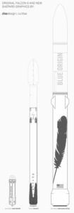
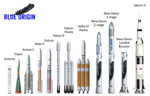
A more detailed size comparison between New Shepard, Falcon 9 and New Glenn is shown in the following diagram.

  Source: zisadesign I /u/zisa

The scale-up from New Shepard, which is not yet operational, to New Glenn is tremendous. The specified payload mass for the two-stage version of New Glenn is:

  • 99,000 pounds (45 metric tons, 45,000 kg) to LEO,
  • 29,000 pounds (13 metric tons, 13,000 kg) to GTO

The three-stage New Glenn will carry heavier payloads.

The first stage of the New Glenn booster is being designed to fly to a designated landing site to be recovered. Aerodynamic surfaces on the first stage will give New Glenn more aerodynamic maneuvering capability than the SpaceX Falcon during the descent to landing. On 7 March 2017, Jeff Bezos gave the following details on the recovery of the first stage.

“Those aerodynamic surfaces allow us to operate with very high availability in very high wind conditions……..We don’t want to constrain the availability of launch based on the availability of the landing of the reusable booster. We put a lot of effort into letting the vehicle fly back with aerodynamic surface control instead of with propulsion.”

Of course, rocket propulsion is needed for the final phase of landing on a large, moving platform at sea. The first stage has six extendable landing legs, and can land safely if only five deploy.
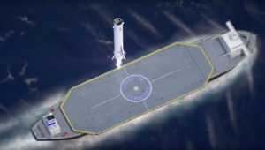
New Glenn landing. Source: Blue Origin

You’ll find a short animated video showing the launch and recovery process for New Glenn at the following link:

https://www.blueorigin.com/#youtubeBTEhohh6eYk

New Glenn flights are expected to start in 2020, about three years after the first SpaceX Falcon Heavy flight.

What are other launch vehicle competitors doing?

No other operational or planned launch vehicles offer the extent of reusability found in the SpaceX Falcon and ITS and the Blue Origin New Shepard and New Glenn. The following launch vehicles will offer only partial reusability.

NASA: partially-reusable Space Launch System (SLS)

 NASA is developing the SLS to launch heavy payloads into Earth orbit and to launch the Orion manned spacecraft on a variety of near-Earth and deep space missions. As shown in the following diagram,  the SLS booster rocket has a large, liquid-fueled, two-stage core flanked by two large solid rocket boosters manufactured by Orbital ATK.

SLS is designed to put 150,000 to 290,000 pounds (70,000 to 130,000 kg) into LEO.
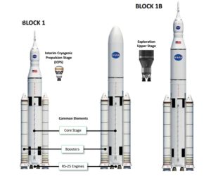
SLS launch vehicle: Source: NASA

As with the NASA Space Shuttle, the solid rocket boosters are designed to be recovered and reused. However, the liquid-fueled first stage booster is expendable; not designed for reuse.

United Launch Alliance (ULA): partially-reusable Vulcan

ULA currently provides medium- and heavy-lift launch with the expendable Atlas V, Delta III and Delta IV boosters. In April 2015, ULA announced that they were developing Vulcan as their Next-Generation Launch System (NGLS) to support a wide variety of Earth-orbital and interplanetary missions. In August 2016, ULA announced plans to qualify Vulcan for manned space missions.

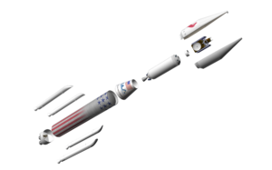
As shown in the following diagram, Vulcan is comprised of a liquid-fueled, two-stage core rocket that can be augmented with up to six solid rocket boosters as needed for the specific mission. This basic architecture is quite similar to ULA’s current Delta III booster, but on a larger scale.

Vulcan launch vehicle. Source: ULA

Vulcan’s maximum payload capacity is expected to fall between ULA’s current Atlas V and Delta IV boosters. ULA expects that “bare bones” Vulcan launch services will sell for half the price of an Atlas V, which is less costly to fly than the Delta IV.

The Vulcan first stage is not designed to be recovered as a unit and reused like the SpaceX Falcon. Instead, ULA is planning a future version that will be partially reusable. In this version, the engines will be designed to detach from the booster after engine cutoff, descend through the atmosphere inside a heat shield, and deploy a parachute for final descent and recovery.

European Space Agency (ESA): expendable Ariane 5 & partially-reusable Ariane 6

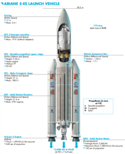
ESA’s current Ariane 5 medium- to heavy-lift booster has a two-stage, liquid-fueled core rocket flanked by two large solid rocket boosters. The basic configuration of Ariane 5 is shown in the following diagram. Ariane V is an expendable booster, not designed for reuse.

Ariane 5. Source: Arianespace

Ariane 5 first flew in June 1996 and has been employed on a wide variety of Earth orbital and interplanetary missions. Versions of Ariane 5 can deliver a payload of more than 44,000 pounds (20,000 kg) to LEO or 23,100 pounds (10,735 kg) to GTO.

In 2014, ESA announced the basic configuration of the Ariane 6 launch vehicle. Like Ariane 5, Arian 6 will have a two-stage, liquid-fueled core rocket flanked by solid rocket boosters.
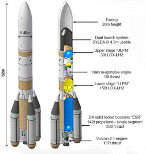
Ariane 6.  Source: adapted from BBC

Two versions are being developed:

  • Ariane 62, with two solid rocket boosters capable of launching about 11,000 pounds (5,000 kg) to GTO
  • Ariane 64, with four solid rocket boosters capable of launching about 24,000 pounds (11,000 kg) to GTO

Ariane 62 and 64 are expendable boosters, not designed for reuse.

In 2015, Airbus Defense and Space announced plans to develop a partially reusable first stage named Adeline that could enter service on a future version of Ariane 6 in the 2025 – 2030 time frame. Like ULA’s plans for Vulcan, only the Ariane 6 first stage high-value parts (i.e., the engine) would be recovered for reuse.

Stratolaunch Systems: giant aircraft plus potentially reusable, air-launched rocket booster

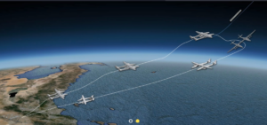
Paul Allen’s firm Stratolaunch Systems is building what will become the world’s largest aircraft, for use as an airborne launch platform for a variety of booster rockets that will take small-to-medium payloads into Earth orbit. The Stratolaunch Carrier will have two fuselages, six jet engines, a length of 238 feet (72 m), and a wingspan of 385 feet (117 m). The giant plane is designed to carry a rocket and payload with a combined weight of up to 550,000 pounds (250,000 kg) to a launch altitude of about 30,000 ft (9,144 m). Payloads up to 13,500 pounds (6,136 kg) can be delivered to LEO. The Stratolaunch Carrier can fly more than 1,000 miles to reach the launch point, giving it unprecedented operational flexibility for delivering payloads to orbit. An example mission profile is shown in the following figure.

Source: Stratolaunch

In 2014, Sierra Nevada Corporation (SNC) announced that it planned to use Stratolaunch as the launch platform for a scaled version of its Dream Chaser reusable spacecraft, initially for unmanned missions and later for manned missions with up to three astronauts. As shown in the following concept drawing, Dream Chaser appears to mounted on a winged, recoverable booster rocket.  For more information on the Dream Chaser reusable spacecraft, visit the SNC website at the following link:

https://www.sncorp.com

Stratolauncher Carrier with Dream Chaser. Source: Sierra Nevada

In 2014, a planned partnership between Stratolaunch Systems and SpaceX for an air-dropped version of the Falcon booster failed to materialize. In October 2016, Stratolaunch announced a partnership with Orbital ATK, which will provide Pegasus XL expendable boosters for use in launching small satellites into Earth orbit from the Stratolaunch aircraft.

The Stratolaunch Carrier was reported to be 76% complete in 2016. Stratolaunch Systems expects the aircraft to be operational by the end of this decade. You’ll find more information on Stratolaunch here:

http://www.stratolaunch.com

Other launch systems

You’ll find a list of worldwide orbital launch systems at the following link.  Most of these are expendable launch systems.

https://en.wikipedia.org/wiki/List_of_orbital_launch_systems

A comparison of these orbital launch systems is available here:

https://en.wikipedia.org/wiki/Comparison_of_orbital_launch_systems

Not included in the above list is the new Next Generation Launch (NGL) System announced by Orbital ATK on 6 April 2017. Two versions of this new, expendable, three-stage booster will be developed to handle medium-to-large payloads, roughly comparable to the payload capability of the SpaceX Falcon 9 reusable booster. The first two stages of the NGL System will be solid fueled.   First flight is planned for 2021. You’ll find a fact sheet on the NGL system at the following link:

http://www.orbitalatk.com/flight-systems/space-launch-vehicles/NGL/docs/BR17001_3862%20NGL_Final%20and%20Approved.pdf

In conclusion

In the highly competitive launch vehicle market, booster reusability should yield a significant economic advantage. In the long run, demonstrating better launch service economies will determine the success or failure of reusable launch vehicles.

While SpaceX and Blue Origin have demonstrated the technical ability to recover and reuse the first stage of a launch vehicle, they have not yet demonstrated the long-term economic value of that capability. In 2017, SpaceX plans to re-fly about six Falcon 9 v1.2 boosters, with even more recycled boosters to be launched in 2018. Blue Origin will likely start New Shepard passenger flights in 2018.

I’m betting that SpaceX and Blue Origin will be successful and reusable boosters will find a permanent role in reducing the price for delivering cargo and people into space.
Grand Finale of the Cassini Mission to Saturn

Peter Lobner

The National Aeronautics and Space Administration’s (NASA’s) Cassini spacecraft was launched on 15 October 1997 and cruised through interplanetary space for seven years before arriving at Saturn on 30 June 2004. The Cassini spacecraft carried the European Space Agency’s (ESA’s) Huygens probe, which landed on Saturn’s largest moon, Titan, on 14 January 2005. Since then, Cassini has been performing a series of missions in orbit around Saturn, returning spectacular images and collecting scientific data on the ringed planet and its many moons.

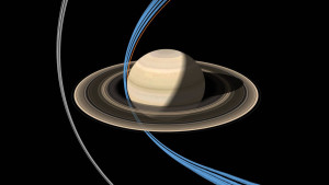
In 2017, Cassini is performing its Grand Finale in a highly elliptical polar orbit around Saturn. The geometry for this orbital flight path is shown in the following diagram.

Cassini_20161205cSource: NASA/JPL-Caltech

In the first phase of the Grand Finale (grey orbits in the above diagram), which is underway now, Cassini’s orbit crosses the plane of Saturn’s equatorial ring system just outside the F-ring (there are just two rings outside of the F-ring: G and E). Later in 2017, Cassini’s polar orbit will be adjusted to cross the plane of the ring system insider the innermost D-ring (blue orbits). From there the spacecraft will gradually descend toward Saturn in a region that has never before been explored. The mission will end when Cassini is destroyed somewhere in Saturn’s atmosphere (orange orbit). This is scheduled to occur on September 15, 2017 at 5:07 a.m. PDT.

NASA’s Cassini mission website is at the following link:

https://www.nasa.gov/mission_pages/cassini/main/index.html

You’ll find a NASA fact sheet on the Grand Finale here:

https://saturn.jpl.nasa.gov/legacy/files/Cassini_Grand_Finale_Fact_Sheet_508.pdf

You can follow the countdown to the final plunge into Saturn’s atmosphere and also review the entire mission timeline and other resources here:

https://saturn.jpl.nasa.gov/the-journey/timeline/#the-grand-finale

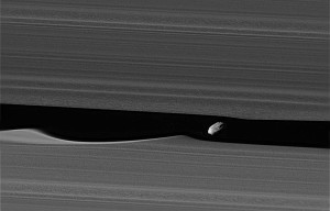
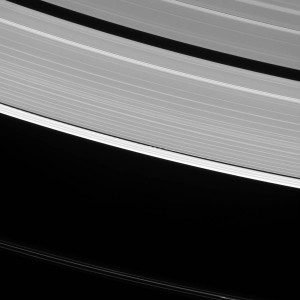
A few Grand Finale images taken during recent ring-grazing orbits past the F-ring are shown below.  The source of these three images and captions are: NASA/JPL-Caltech/Space Science Institute

Cassini_pia21056_deblurred cropThe above image, taken 16 January 2017, shows Saturn’s moon Daphnis (5 miles, 8 kilometers across), which orbits within the 26 mile (42 km) wide Keeler Gap (between the F and A rings). The gap appears foreshortened because of the viewing angle. The little moon’s gravity raises waves in the edges of the gap in both the horizontal and vertical directions.

Cassini_pia20511-1041Waves created by Daphnis are visible in this wider-angle view of the ring system. The F-ring is the bright, narrow ring crossing the center of the image. Since the moon moves in and out of the ring-plane, and closer to and farther from the rings’ edges as it orbits, the waves it makes change over time.

Cassini_pia21055-1041This image, taken on 18 December 2016, is one of the highest-resolution views ever taken of Saturn’s moon Pandora (52 miles, 84 kilometers across), which orbits just outside the F-ring.

13 April 2017 Update – Cassini’s close-up view of Saturn’s moon Pan

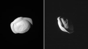
In early March, Cassini imaged Pan, which is one of Saturn’s innermost moons. As you can see in the following photos, this small moon (diameter of 221.7 miles, 35 km) has a most unusual shape. It isn’t known if the ridge circling the moon is solid, or a loose aggregation of particles with a very steep slope enabled by the moons weak gravity.

Source: NASA/JPL-Caltech/Space Science Institute

The NASA announcement and more photos of Pan are at the following link:

https://www.nasa.gov/image-feature/jpl/cassini-reveals-strange-shape-of-saturns-moon-pan

NuSTAR Provides a High-Resolution X-ray View of our Universe

Peter Lobner

In my 6 March 2016 post, “Remarkable Multispectral View of Our Milky Way Galaxy,” I briefly discussed several of the space-based observatories that are helping to develop a deeper understanding of our galaxy and the universe. One space-based observatory not mentioned in that post is the National Aeronautics and Space Administration (NASA) Nuclear Spectroscopic Telescope Array (NuSTAR) X-Ray observatory, which was launched on 13 June 2012 into a near equatorial, low Earth orbit. NASA describes the NuSTAR mission as follows:

“The NuSTAR mission has deployed the first orbiting telescopes to focus light in the high energy X-ray (6 – 79 keV) region of the electromagnetic spectrum. Our view of the universe in this spectral window has been limited because previous orbiting telescopes have not employed true focusing optics, but rather have used coded apertures that have intrinsically high backgrounds and limited sensitivity.

During a two-year primary mission phase, NuSTAR will map selected regions of the sky in order to:

1.  Take a census of collapsed stars and black holes of different sizes by surveying regions surrounding the center of own Milky Way Galaxy and performing deep observations of the extragalactic sky;

2.  Map recently-synthesized material in young supernova remnants to understand how stars explode and how elements are created; and

3.  Understand what powers relativistic jets of particles from the most extreme active galaxies hosting supermassive black holes.”

 The NuSTAR spacecraft is relatively small, with a payload mass of only 171 kg (377 lb). In it’s stowed configuration, this compact satellite was launched by an Orbital ATK Pegasus XL booster, which was carried aloft by the Stargazer L-1011 aircraft to approximately 40,000 feet over open ocean, where the booster was released and carried the small payload into orbit.

Orbital ATK L-1011 StargazerStargazer L-1011 dropping a Pegasus XL booster. Source: Orbital ATK

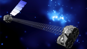
In orbit, the solar-powered NuSTAR extended to a total length of 10.9 meters (35.8 feet) in the orbital configuration shown below. The extended spacecraft gives the X-ray telescope a 10 meter (32.8 foot) focal length.

NuSTAR satelliteNuSTAR orbital configuration. Source: NASA / JPL – Caltech

NASA describes the NuSTAR X-Ray telescope as follows:

“The NuSTAR instrument consists of two co-aligned grazing incidence X-Ray telescopes (Wolter type I) with specially coated optics and newly developed detectors that extend sensitivity to higher energies as compared to previous missions such as NASA’a Chandra X-Ray Observatory launched in 1999 and the European Space Agency’s (ESA) XMM-Newton (aka High-throughput X-Ray Spectrometry Mission), also launched in 1999…….. The observatory will provide a combination of sensitivity, spatial, and spectral resolution factors of 10 to 100 improved over previous missions that have operated at these X-ray energies.”

The NASA NuSTAR mission website is at the following link:

https://www.nasa.gov/mission_pages/nustar/main/index.html

Some examples of NuSTAR findings posted on this website are summarized below.

X-ray emitting structures of galaxies identified

In the following composite image of Galaxy 1068, high-energy X-rays (shown in magenta) captured by NuSTAR are overlaid on visible-light images from both NASA’s Hubble Space Telescope and the Sloan Digital Sky Survey.

Galaxy 1068Galaxy 1068. Source: NASA/JPL-Caltech/Roma Tre Univ

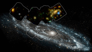
Below is a more detailed X-ray view of portion of the Andromeda galaxy (aka M31), which is the galaxy nearest to our Milky Way. On 5 January 2017, NASA reported:

“The space mission has observed 40 ‘X-ray binaries’ — intense sources of X-rays comprised of a black hole or neutron star that feeds off a stellar companion.

Andromeda is the only large spiral galaxy where we can see individual X-ray binaries and study them in detail in an environment like our own.”

In the following image, the portion of the Andromeda galaxy surveyed by NuSTAR is in the smaller outlined area. The larger outlined area toward the top of this image is the corresponding X-ray view of the surveyed area.

Andromeda galaxyAndromeda galaxy.  Source: NASA/JPL-Caltech/GSFC

NASA describes the following mechanism for X-ray binaries to generate the observed intense X-ray emissions:

“In X-ray binaries, one member is always a dead star or remnant formed from the explosion of what was once a star much more massive than the sun. Depending on the mass and other properties of the original giant star, the explosion may produce either a black hole or neutron star. Under the right circumstances, material from the companion star can “spill over” its outermost edges and then be caught by the gravity of the black hole or neutron star. As the material falls in, it is heated to blazingly high temperatures, releasing a huge amount of X-rays.”

You can read more on this NuStar discovery at the following link:

https://www.nasa.gov/feature/jpl/Andromeda-Galaxy-Scanned-with-High-Energy-X-ray-Vision

Composition of supernova remnants determined

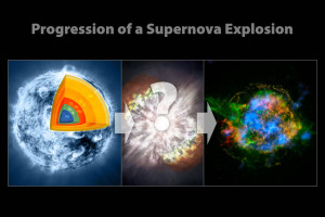
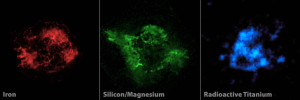
Cassiopeia A is within our Milky Way, about 11,000 light-years from Earth. The following NASA three-panel chart shows Cassiopeia A originally as an iron-core star. After going supernova, Cassiopeia A scattered its outer layers, which have distributed into the diffuse structure we see today, known as the supernova remnant. The image in the right-hand panel is a composite X-ray image of the supernova remnant from both the Chandra X-ray Observatory and NuStar.

Cassiopeia ASource: NASA/CXC/SAO/JPL-Caltech

In the following three-panel chart, the composite image (above, right) is unfolded into its components. Red shows iron and green shows both silicon and magnesium, as seen by the Chandra X-ray Observatory. Blue shows radioactive titanium-44, as mapped by NuSTAR.

 Cassiopeia A componentsSource: NASA/JPL-Caltech/CXC/SAO

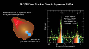
Supernova 1987A is about 168,000 light-years from Earth in the Large Magellanic Cloud. As shown below, NuSTAR also observed titanium in this supernova remnant.

SN 1987A titaniumSource: NASA/JPL-Caltech/UC Berkeley

These observations are providing new insights into how massive stars explode into supernovae.

Severe Space Weather Events Will Challenge Critical Infrastructure Systems on Earth

Peter Lobner

What is space weather?

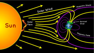
Space weather is determined largely by the variable effects of the Sun on the Earth’s magnetosphere. The basic geometry of this relationship is shown in the following diagram, with the solar wind always impinging on the Earth’s magnetic field and transferring energy into the magnetosphere.  Normally, the solar wind does not change rapidly, and Earth’s space weather is relatively benign. However, sudden disturbances on the Sun produce solar flares and coronal holes that can cause significant, rapid variations in Earth’s space weather.

auroradiagramSource: http://scijinks.jpl.nasa.gov/aurora/

A solar storm, or geomagnetic storm, typically is associated with a large-scale magnetic eruption on the Sun’s surface that initiates a solar flare and an associated coronal mass ejection (CME). A CME is a giant cloud of electrified gas (solar plasma.) that is cast outward from the Sun and may intersect Earth’s orbit. The solar flare also releases a burst of radiation in the form of solar X-rays and protons.

The solar X-rays travel at the speed of light, arriving at Earth’s orbit in 8 minutes and 20 seconds. Solar protons travel at up to 1/3 the speed of light and take about 30 minutes to reach Earth’s orbit. NOAA reports that CMEs typically travel at a speed of about 300 kilometers per second, but can be as slow as 100 kilometers per second. The CMEs typically take 3 to 5 days to reach the Earth and can take as long as 24 to 36 hours to pass over the Earth, once the leading edge has arrived.

If the Earth is in the path, the X-rays will impinge on the Sun side of the Earth, while charged particles will travel along magnetic field lines and enter Earth’s atmosphere near the north and south poles. The passing CME will transfer energy into the magnetosphere.

Solar storms also may be the result of high-speed solar wind streams (HSS) that emanate from solar coronal holes (an area of the Sun’s corona with a weak magnetic field) with speeds up to 3,000 kilometers per second. The HSS overtakes the slower solar wind, creating turbulent regions (co-rotating interaction regions, CIR) that can reach the Earth’s orbit in as short as 18 hours. A CIR can deposit as much energy into Earth’s magnetosphere as a CME, but over a longer period of time, up to several days.

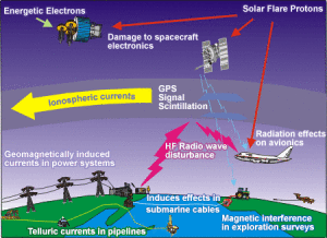
Solar storms can have significant effects on critical infrastructure systems on Earth, including airborne and space borne systems. The following diagram highlights some of these vulnerabilities.

Canada Geomagnetic-Storms-effects-space-weather-technologyEffects of Space Weather on Modern Technology. Source: SpaceWeather.gc.ca

Characterizing space weather

The U.S. National Oceanic and Atmospheric Administration (NOAA) Space Weather Prediction Center (SWPC) uses the following three scales to characterize space weather:

  • Geomagnetic storms (G): intensity measured by the “planetary geomagnetic disturbance index”, Kp, also known as the Geomagnetic Storm or G-Scale
  • Solar radiation storms (S): intensity measured by the flux level of ≥ 10 MeV solar protons at GEOS (Geostationary Operational Environmental Satellite) satellites, which are in synchronous orbit around the Earth.
  • Radio blackouts (R): intensity measured by flux level of solar X-rays at GEOS satellites.

Another metric of space weather is the Disturbance Storm Time (Dst) index, which is a measure of the strength of a ring current around Earth caused by solar protons and electrons. A negative Dst value means that Earth’s magnetic field is weakened, which is the case during solar storms.

A single solar disturbance (a CME or a CIR) will affect all of the NOAA scales and Dst to some degree.

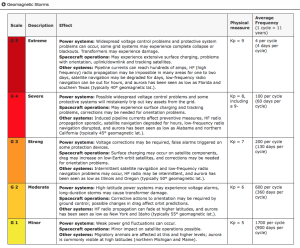
As shown in the following NOAA table (click on table to enlarge), the G-scale describes the infrastructure effects that can be experienced for five levels of geomagnetic storm severity. At the higher levels of the scale, significant infrastructure outages and damage are possible.

NOAA geomag storm scale

There are similar tables for Solar Radiation Storms and Radio Blackouts on the NOAA SWPC website at the following link:

http://www.swpc.noaa.gov/noaa-scales-explanation

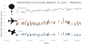
Another source for space weather information is the spaceweather.com website, which contains some information not found on the NOAA SWPC website. For example, this website includes a report of radiation levels in the atmosphere at aviation altitudes and higher in the stratosphere. In the following chart, “dose rates are expressed as multiples of sea level. For instance, we see that boarding a plane that flies at 25,000 feet exposes passengers to dose rates ~10x higher than sea level. At 40,000 feet, the multiplier is closer to 50x.”

 spaceweather rad levelsSource: spaceweather.com

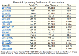
You’ll also find a report of recent and upcoming near-Earth asteroids on the spaceweather.com website. This definitely broadens the meaning of “space weather.” As you can seen the in the following table, no close encounters are predicted over the next two months.

spaceweather NEOs

In summary, the effects of a solar storm may include:

  • Interference with or damage to spacecraft electronics: induced currents and/or energetic particles may have temporary or permanent effects on satellite systems
  • Navigation satellite (GPS, GLONASS and Galileo) UHF / SHF signal scintillation (interference)
  • Increased drag on low Earth orbiting satellites: During storms, currents and energetic particles in the ionosphere add energy in the form of heat that can increase the density of the upper atmosphere, causing extra drag on satellites in low-earth orbit
  • High-frequency (HF) radio communications and low-frequency (LF) radio navigation system interference or signal blackout
  • Geomagnetically induced currents (GICs) in long conductors can trip protective devices and may damage associated hardware and control equipment in electric power transmission and distribution systems, pipelines, and other cable systems on land or undersea.
  • Higher radiation levels experienced by crew & passengers flying at high latitudes in high-altitude aircraft or in spacecraft.

For additional information, you can download the document, “Space Weather – Effects on Technology,” from the Space Weather Canada website at the following link:

http://ftp.maps.canada.ca/pub/nrcan_rncan/publications/ess_sst/292/292124/gid_292124.pdf

Historical major solar storms

The largest recorded geomagnetic storm, known as the Carrington Event or the Solar Storm of 1859, occurred on 1 – 2 September 1859. Effects included:

  • Induced currents in long telegraph wires, interrupting service worldwide, with a few reports of shocks to operators and fires.
  • Aurorea seen as far south as Hawaii, Mexico, Caribbean and Italy.

This event is named after Richard Carrington, the solar astronomer who witnessed the event through his private observatory telescope and sketched the Sun’s sunspots during the event. In 1859, no electric power transmission and distribution system, pipeline, or cable system infrastructure existed, so it’s a bit difficult to appreciate the impact that a Carrington-class event would have on our modern technological infrastructure.

A large geomagnetic storm in March 1989 has been attributed as the cause of the rapid collapse of the Hydro-Quebec power grid as induced voltages caused protective relays to trip, resulting in a cascading failure of the power grid. This event left six million people without electricity for nine hours.

A large solar storm on 23 July 2012, believed to be similar in magnitude to the Carrington Event, was detected by the STEREO-A (Solar TErrestrial RElations Observatory) spacecraft, but the storm passed Earth’s orbit without striking the Earth. STEREO-A and its companion, STEREO-B, are in heliocentric orbits at approximately the same distance from the Sun as Earth, but displaced ahead and behind the Earth to provide a stereoscopic view of the Sun.

You’ll find a historical timeline of solar storms, from the 28 August 1859 Carrington Event to the 29 October 2003 Halloween Storm on the Space Weather website at the following link:

http://www.solarstorms.org/SRefStorms.html

Risk from future solar storms

A 2013 risk assessment by the insurance firm Lloyd’s and consultant engineering firm Atmospheric and Environmental Research (AER) examined the impact of solar storms on North America’s electric grid.

electrical-power-transmission-lines-united-states-useiaU.S. electric power transmission grid. Source: EIA

Here is a summary of the key findings of this risk assessment:

  • A Carrington-level extreme geomagnetic storm is almost inevitable in the future. Historical auroral records suggest a return period of 50 years for Quebec-level (1989) storms and 150 years for very extreme storms, such as the Carrington Event (1859).
  • The risk of intense geomagnetic storms is elevated near the peak of the each 11-year solar cycle, which peaked in 2015.
  • As North American electric infrastructure ages and we become more dependent on electricity, the risk of a catastrophic outage increases with each peak of the solar cycle.
  • Weighted by population, the highest risk of storm-induced power outages in the U.S. is along the Atlantic corridor between Washington D.C. and New York City.
  • The total U.S. population at risk of extended power outage from a Carrington-level storm is between 20-40 million, with durations from 16 days to 1-2 years.
  • Storms weaker than Carrington-level could result in a small number of damaged transformers, but the potential damage in densely populated regions along the Atlantic coast is significant.
  • A severe space weather event that causes major disruption of the electricity network in the U.S. could have major implications for the insurance industry.

The Lloyds report identifies the following relative risk factors for electric power transmission and distribution systems:

  • Magnetic latitude: Higher north and south “corrected” magnetic latitudes are more strongly affected (“corrected” because the magnetic North and South poles are not at the geographic poles). The effects of a major storm can extend to mid-latitudes.
  • Ground conductivity (down to a depth of several hundred meters): Geomagnetic storm effects on grounded infrastructure depend on local ground conductivity, which varies significantly around the U.S.
  • Coast effect: Grounded systems along the coast are affected by currents induced in highly-conductive seawater.
  • Line length and rating: Induced current increases with line length and the kV rating (size) of the line.
  • Transformer design: Lloyds noted that extra-high voltage (EHV) transformers (> 500 kV) used in electrical transmission systems are single-phase transformers. As a class, these are more vulnerable to internal heating than three-phase transformers for the same level of geomagnetically induced current.

Combining these risk factors on a county-by-county basis produced the following relative risk map for the northeast U.S., from New York City to Maine. The relative risk scale covers a range of 1000. The Lloyd’s report states, “This means that for some counties, the chance of an average transformer experiencing a damaging geomagnetically induced current is more than 1000 times that risk in the lowest risk county.”

Lloyds relative risk Relative risk of power outage from geomagnetic storm. Source: Lloyd’s

You can download the complete Lloyd risk assessment at the following link:

https://www.lloyds.com/news-and-insight/risk-insight/library/natural-environment/solar-storm

In May 2013, the United States Federal Energy Regulatory Commission issued a directive to the North American Electric Reliability Corporation (NERC) to develop reliability standards to address the impact of geomagnetic disturbances on the U.S. electrical transmission system. One part of that effort is to accurately characterize geomagnetic induction hazards in the U.S. The most recent results were reported in the 19 September 2016, a paper by J. Love et al., “Geoelectric hazard maps for the continental United States.” In this report the authors characterize geography and surface impedance of many sites in the U.S. and explain how these characteristics contribute to regional differences in geoelectric risk. Key findings are:

“As a result of the combination of geographic differences in geomagnetic activity and Earth surface impedance, once-per-century geoelectric amplitudes span more than 2 orders of magnitude (factor of 100) and are an intricate function of location.”

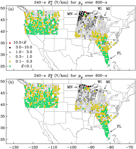
“Within regions of the United States where a magnetotelluric survey was completed, Minnesota (MN) and Wisconsin (WI) have some of the highest geoelectric hazards, while Florida (FL) has some of the lowest.”

“Across the northern Midwest …..once-per-century geoelectric amplitudes exceed the 2 V/km that Boteler ……has inferred was responsible for bringing down the Hydro-Québec electric-power grid in Canada in March 1989.”

The following maps from this paper show maximum once-per-century geoelectric exceedances at EarthScope and U.S. Geological Survey magnetotelluric survey sites for geomagnetic induction (a) north-south and (b) east-west. In these maps, you can the areas of the upper Midwest that have the highest risk.

JLove Sep2016_grl54980-fig-0004

The complete paper is available online at the following link:

http://onlinelibrary.wiley.com/doi/10.1002/2016GL070469/full

Is the U.S. prepared for a severe solar storm?

The quick answer, “No.” The possibility of a long-duration, continental-scale electric power outage exists. Think about all of the systems and services that are dependent on electric power in your home and your community, including communications, water supply, fuel supply, transportation, navigation, food and commodity distribution, healthcare, schools, industry, and public safety / emergency response. Then extrapolate that statewide and nationwide.

In October 2015, the National Science and Technology Council issued the, “National Space Weather Action Plan,” with the following stated goals:

  • Establish benchmarks for space-weather events: induced geo-electric fields), ionizing radiation, ionospheric disturbances, solar radio bursts, and upper atmospheric expansion
  • Enhance response and recovery capabilities, including preparation of an “All-Hazards Power Outage Response and Recovery Plan.
  • Improve protection and mitigation efforts
  • Improve assessment, modeling, and prediction of impacts on critical infrastructure
  • Improve space weather services through advancing understanding and forecasting
  • Increase international cooperation, including policy-level acknowledgement that space weather is a global challenge

The Action Plan concludes:

“The activities outlined in this Action Plan represent a merging of national and homeland security concerns with scientific interests. This effort is only the first step. The Federal Government alone cannot effectively prepare the Nation for space weather; significant effort must go into engaging the broader community. Space weather poses a significant and complex risk to critical technology and infrastructure, and has the potential to cause substantial economic harm. This Action Plan provides a road map for a collaborative and Federally-coordinated approach to developing effective policies, practices, and procedures for decreasing the Nation’s vulnerabilities.”

You can download the Action Plan at the following link:

https://www.whitehouse.gov/sites/default/files/microsites/ostp/final_nationalspaceweatheractionplan_20151028.pdf

To supplement this Action Plan, on 13 October 2016, the President issued an Executive Order entitled, “Coordinating Efforts to Prepare the Nation for Space Weather Events,” which you can read at the following link:

https://www.whitehouse.gov/the-press-office/2016/10/13/executive-order-coordinating-efforts-prepare-nation-space-weather-events

Implementation of this Executive Order includes the following provision (Section 5):

Within 120 days of the date of this order, the Secretary of Energy, in consultation with the Secretary of Homeland Security, shall develop a plan to test and evaluate available devices that mitigate the effects of geomagnetic disturbances on the electrical power grid through the development of a pilot program that deploys such devices, in situ, in the electrical power grid. After the development of the plan, the Secretary shall implement the plan in collaboration with industry.”

So, steps are being taken to better understand the potential scope of the space weather problems and to initiate long-term efforts to mitigate their effects. Developing a robust national mitigation capability for severe space weather events will take several decades. In the meantime, the nation and the whole world remain very vulnerable to sever space weather.

Today’s space weather forecast

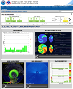
Based on the Electric Power Community Dashboard from NOAA’s Space Weather Prediction Center, it looks like we have mild space weather on 31 December 2016. All three key indices are green: R (radio blackouts), S (solar radiation storms), and G (geomagnetic storms). That’s be a good way to start the New Year.

NOAA space weather 31Dec2016

See your NOAA space weather forecast at:

http://www.swpc.noaa.gov/communities/electric-power-community-dashboard

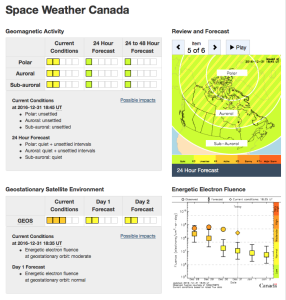
Natural Resources Canada also forecasts mild space weather for the far north.

Canada space weather 31Dec2016You can see the Canadian space weather forecast at the following link:

http://www.spaceweather.gc.ca/index-en.php

4 January 2017 Update: G1 Geomagnetic Storm Approaching Earth

On 2 January, 2017, NOAA’s Space Weather Prediction Center reported that NASA’s STEREO-A spacecraft encountered a 700 kilometer per second HSS that will be pointed at Earth in a couple of days.

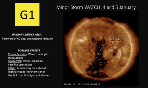
“A G1 (Minor) geomagnetic storm watch is in effect for 4 and 5 January, 2017. A recurrent, polar connected, negative polarity coronal hole high-speed stream (CH HSS) is anticipated to rotate into an Earth-influential position by 4 January. Elevated solar wind speeds and a disturbed interplanetary magnetic field (IMF) are forecast due to the CH HSS. These conditions are likely to produce isolated periods of G1 storming beginning late on 4 January and continuing into 5 January. Continue to check our SWPC website for updated information and forecasts.”

The coronal hole is visible as the darker regions in the following image from NASA’s Solar Dynamics Observatory (SDO) satellite, which is in a geosynchronous orbit around Earth.

NOAA SWPC 4Jan2017Source: NOAA SWPC

SDO has been observing the Sun since 2010 with a set of three instruments:

  • Helioseismic and Magnetic Imager (HMI)
  • Extreme Ultraviolet Variability Experiment (EVE)
  • Atmospheric Imaging Assembly (AIA)

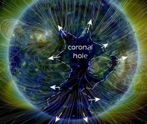
The above image of the coronal hole was made by SDO’s AIA. Another view, from the spaceweather.com website, provides a clearer depiction of the size and shape of the coronal hole creating the current G1 storm.

spaceweather coronal holeSource: spaceweather.com

You’ll find more information on the SDO satellite and mission on the NASA website at the following link:

https://sdo.gsfc.nasa.gov/mission/spacecraft.php

There’s Increased Worldwide Interest in Asteroid and Moon Mining Missions

Peter Lobner

In my 31 December 2015 post, “Legal Basis Established for U.S. Commercial Space Launch Industry Self-regulation and Commercial Asteroid Mining,” I commented on the likely impact of the “U.S. Commercial Space Launch Competitiveness Act,” (2015 Space Act) which was signed into law on 25 November 2016. A lot has happened since then.

Planetary Resources building technology base for commercial asteroid prospecting

The firm Planetary Resources (Redmond, Washington) has a roadmap for developing a working space-based prospecting system built on the following technologies:

  • Space-based observation systems: miniaturization of hyperspectral sensors and mid-wavelength infrared sensors.
  • Low-cost avionics software: tiered and modular spacecraft avionics with a distributed set of commercially-available, low-level hardened elements each handling local control of a specific spacecraft function.
  • Attitude determination and control systems: distributed system, as above
  • Space communications: laser communications
  • High delta V small satellite propulsion systems: “Oberth maneuver” (powered flyby) provides most efficient use of fuel to escape Earth’s gravity well

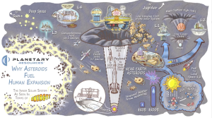
Check out their short video, “Why Asteroids Fuel Human Expansion,” at the following link:

http://www.planetaryresources.com/asteroids/#asteroids-intro

 Planetary Resources videoSource: Planetary Resources

For more information, visit the Planetary Resources home page at the following link:

http://www.planetaryresources.com/#home-intro

Luxembourg SpaceResources.lu Initiative and collaboration with Planetary Resources

On 3 November 2016, Planetary Resources announced funding and a target date for their first asteroid mining mission:

“Planetary Resources, Inc. …. announced today that it has finalized a 25 million euro agreement that includes direct capital investment of 12 million euros and grants of 13 million euros from the Government of the Grand Duchy of Luxembourg and the banking institution Société Nationale de Crédit et d’Investissement (SNCI). The funding will accelerate the company’s technical advancements with the aim of launching the first commercial asteroid prospecting mission by 2020. This milestone fulfilled the intent of the Memorandum of Understanding with the Grand Duchy and its SpaceResources.lu initiative that was agreed upon this past June.”

The homepage for Luxembourg’s SpaceResources.lu Initiative is at the following link:

http://www.spaceresources.public.lu/en/index.html

Here the Grand-Duchy announced its intent to position Luxembourg as a European hub in the exploration and use of space resources.

“Luxembourg is the first European country to set out a formal legal framework which ensures that private operators working in space can be confident about their rights to the resources they extract, i.e. valuable resources from asteroids. Such a legal framework will be worked out in full consideration of international law. The Grand-Duchy aims to participate with other nations in all relevant fora in order to agree on a mutually beneficial international framework.”

Remember the book, “The Mouse that Roared?” Well, here’s Luxembourg leading the European Union (EU) into the business of asteroid mining.

European Space Agency (ESA) cancels Asteroid Impact Mission (AIM)

ESA’s Asteroid Impact Mission (AIM) was planning to send a small spacecraft to a pair of co-orbital asteroids, Didymoon and Didymos, in 2022. Among other goals, this ESA mission was intended to observe the NASA’s Double Asteroid Redirection Test when it impacts Didymoon at high speed. ESA mission profile for AIM is described at the following link:

http://www.esa.int/Our_Activities/Space_Engineering_Technology/Asteroid_Impact_Mission/Mission_profile

On 2 Dec 2016, ESA announced that AIM did not win enough support from member governments and will be cancelled. Perhaps the plans for an earlier commercial asteroid mission marginalized the value of the ESA investment in AIM.

Japanese Aerospace Exploration Agency (JAXA) announces collaboration for lunar resource prospecting, production and delivery

On 16 December 2016, JAXA announced that it will collaborate with the private lunar exploration firm, ispace, Inc. to prospect for lunar resources and then eventually build production and resource delivery facilities on the Moon.

ispace is a member of Japan’s Team Hakuto, which is competing for the Google Lunar XPrize. Team Hakuto describes their mission as follows:

“In addition to the Grand Prize, Hakuto will be attempting to win the Range Bonus. Furthermore, Hakuto’s ultimate target is to explore holes that are thought to be caves or “skylights” into underlying lava tubes, for the first time in human history.  These lava tubes could prove to be very important scientifically, as they could help explain the moon’s volcanic past. They could also become candidate sites for long-term habitats, able to shield humans from the moon’s hostile environment.”

Hakuto is facing the challenges of the Google Lunar XPRIZE and skylight exploration with its unique ‘Dual Rover’ system, consisting of two-wheeled ‘Tetris’ and four-wheeled ‘Moonraker.’ The two rovers are linked by a tether, so that Tetris can be lowered into a suspected skylight.”

Hakuto rover-with-tail

Team Hakuto dual rover. Source: ispace, Inc.

So far, the team has won one Milestone Prize worth $500,000 and must complete its lunar mission by the end of 2017 in order to be eligible for the final prizes. You can read more about Team Hakuto and their rover on the Google Lunar XPrize website at the following link:

http://lunar.xprize.org/teams/hakuto

Building on this experience, and apparently using the XPrize rover, ispace has proposed the following roadmap to the moon (click on the graphic to enlarge).

ispace lunar roadmapSource: ispace, Inc.

This ambitious roadmap offers an initial lunar resource utilization capability by 2030. Ice will be the primary resource sought on the Moon. Ispace reports:

“According to recent studies, the Moon houses an abundance of precious minerals on its surface, and an estimated 6 billion tons of water ice at its poles. In particular, water can be broken down into oxygen and hydrogen to produce efficient rocket fuel. With a fuel station established in space, the world will witness a revolution in the space transportation system.”

The ispace website is at the following link:

http://ispace-inc.com

Strange Things are Happening Underground

Peter Lobner

In the last month, there have been reports of some very unexpected things happening under the surface of the earth. I’m talking about subduction plates that maintain their structure as they dive toward the Earth’s core and “jet streams” in the Earth’s core itself. Let’s take a look at these interesting phenomena.

What happens to subduction plates?

Oceanic tectonic plates are formed as magma wells up along mid-ocean ridges, forming new lithospheric rock that spread away from both sides of the ridge, building two different tectonic plates. This is known as a divergent plate boundary.

As tectonic plates move slowly across the Earth’s surface, each one moves differently than the adjacent plates. In simple terms, this relative motion at the plate interfaces is either a slipping, side-by-side (transform) motion, or a head-to-head (convergent) motion.

A map of the Earth showing the tectonic plates and the nature of the relative motion at the plate interfaces is shown below (click on the image to enlarge).

ESRT Page5

Source: http://www.regentsearth.com/

When two tectonic plate converge, one will sink under (subduct) the other. In the case of an oceanic plate converging with a continental plate, the heavier oceanic plate always sinks under the continental plate and may cause mountain building along the edge of the continental plate. When two oceanic plates converge, one will subduct the other, creating a deep mid-ocean trench (i.e., Mariana trench) and possibly forming an arc of islands on the overriding plate (i.e., Aleutian Islands and south Pacific island chains). In the diagram above, you can see that some subduction zones are quite long.

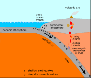
subd_zoneSource: http://www.columbia.edu/~vjd1/subd_zone_basic.htm

The above diagram shows the subducting material from an oceanic plate descending deep into the Earth beneath the overriding continental plate.  New research indicates that the subducting plates maintain their structure to a considerable depth below the surface of the Earth.

On 22 November 2016, an article by Paul Voosen, “’Atlas of the Underworld’ reveals oceans and mountains lost to Earth’s history,” was posted on the sciencemag.org website. The author reports:

“A team of Dutch scientists will announce a catalog of 100 subducted plates, with information about their age, size, and related surface rock records, based on their own tomographic model and cross-checks with other published studies.”

“…geoscientists have begun ….peering into the mantel itself, using earthquake waves that pass through Earth’s interior to generate images resembling computerized tomography (CT) scans. In the past few years, improvements in these tomographic techniques have revealed many of these cold, thick slabs as they free fall in slow motion to their ultimate graveyard—heaps of rock sitting just above Earth’s molten core, 2900 kilometers below.”

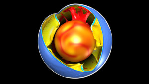
The following concept drawing illustrates how a CT scan of the whole Earth might look, with curtains of subducting material surrounding the molten core.

Atlas_1121_1280x720Source: Science / Fabio Crameri

The author notes that research teams around the world are using more than 20 different models to interpret similar tomographic data. As you might expect, results differ. However, a few points are consistent:

  • The subducting slabs in the upper mantle appear to be stiff, straight curtains of lithospheric rock
  • These slabs may flex but they don’t crumble.
  • These two features make it possible to “unwind” the geologic history of individual tectonic slabs and develop a better understanding of the route each slab took to its present location.
  • The geologic history in subducting slabs only stretches back about 250 million years, which is the time it takes for subducting material to fall from the surface to the bottom of the mantle and be fully recycled.

You can read the fill article by Paul Voosen at the following link:

http://www.sciencemag.org/news/2016/11/atlas-underworld-reveals-oceans-and-mountains-lost-earths-history

Hopefully, the “Atlas of the Underworld” will help focus the dialogue among international research teams toward collaborative efforts to improve and standardize the processes and models for building an integrated CT model of our Earth.

A “jet stream” in the Earth’s core

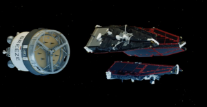
The European Space Agency (ESA) developed the Swarm satellites to make highly accurate and frequent measurements of Earth’s continuously changing magnetic field, with the goal of developing new insights into our planet’s formation, dynamics and environment. The three-satellite Swarm mission was launched on 22 November 2013.

3 satellite SWARMSwarm satellites separating from Russian booster. Source: ESA

ESA’s website for the Swarm mission is at the following link:

http://www.esa.int/Our_Activities/Observing_the_Earth/Swarm/From_core_to_crust

Here ESA explains the value of the measurements made by the Swarm satellites.

“One of the very few ways of probing Earth’s liquid core is to measure the magnetic field it creates and how it changes over time. Since variations in the field directly reflect the flow of fluid in the outermost core, new information from Swarm will further our understanding of the physics and dynamics of Earth’s stormy heart.

The continuous changes in the core field that result in motion of the magnetic poles and reversals are important for the study of Earth’s lithosphere, also known as the ‘crustal’ field, which has induced and remnant magnetized parts. The latter depend on the magnetic properties of the sub-surface rock and the history of Earth’s core field.

We can therefore learn more about the history of the magnetic field and geological activity by studying magnetism in Earth’s crust. As new oceanic crust is created through volcanic activity, iron-rich minerals in the upwelling magma are oriented to magnetic north at the time.

These magnetic stripes are evidence of pole reversals so analyzing the magnetic imprints of the ocean floor allows past core field changes to be reconstructed and also helps to investigate tectonic plate motion.”

Data from the Swarm satellites indicates that the liquid iron part of the Earth’s core has an internal, 420 km (261 miles) wide “jet stream” circling the core at high latitude at a current speed of about 40 km/year (25 miles/year) and accelerating. In geologic terms, this “jet stream” is significantly faster than typical large scale flows in the core. The basic geometry of this “jet stream” is shown in the following diagram.

jet-stream-earth-core-ESA-e1482190909115Source: ESA

These results were published on 19 December 2016 in the article, An accelerating high-latitude jet in Earth’s core,” on the Nature Geoscience website at the following link:

http://www.nature.com/ngeo/journal/vaop/ncurrent/full/ngeo2859.html

A subscription is required for access to the full paper.

The Swarm mission is ongoing. Watch the ESA’s mission website for more news.

The Vision for Manned Exploration and Colonization of Mars is Alive Again

Peter Lobner

On 25 May 1961, President John F. Kennedy made an important speech to a joint session of Congress in which he stated:

“I believe that this nation should commit itself to achieving the goal, before this decade is out, of landing a man on the moon and returning him safely to the Earth.”

This was a very bold statement considering the state-of-the-art of U.S. aerospace technology in mid-1961. Yuri Gagarin became the first man to orbit the Earth on 12 April 1961 in a Soviet Vostok spacecraft and Alan Shepard completed the first Project Mercury suborbital flight on 5 May 1961. No American had yet flown in orbit. It wasn’t until 20 February 1962 that the first Project Mercury capsule flew into Earth orbit with astronaut John Glenn. The Soviets had hit the Moon with Luna 2 and returned photos from the backside of the moon with Luna 3. The U.S had only made one distant lunar flyby with the tiny Pioneer 4 spacecraft. The Apollo manned lunar program was underway, but still in the concept definition phase. The first U.S. heavy booster rocket designed to support the Apollo program, the Saturn 1, didn’t fly until 27 October 1961.

President Kennedy concluded this part of his 25 May 1961 speech with the following admonition:

“This decision (to proceed with the manned lunar program) demands a major national commitment of scientific and technical manpower, materiel and facilities, and the possibility of their diversion from other important activities where they are already thinly spread. It means a degree of dedication, organization and discipline, which have not always characterized our research and development efforts. It means we cannot afford undue work stoppages, inflated costs of material or talent, wasteful interagency rivalries, or a high turnover of key personnel.

New objectives and new money cannot solve these problems. They could in fact, aggravate them further–unless every scientist, every engineer, every serviceman, every technician, contractor, and civil servant gives his personal pledge that this nation will move forward, with the full speed of freedom, in the exciting adventure of space.”

This was the spirit that lead to the great success of the Apollo program, which landed the first men on the Moon, astronauts Neil Armstrong and Ed Aldrin, on 20 July 1969; a little more than 8 years after President Kennedy’s speech.

NASA’s plans for manned Mars exploration

By 1964, exciting concepts for manned Mars exploration vehicles were being developed under National Aeronautics and Space Administration (NASA) contract by several firms. One example is a Mars lander design shown below from Aeronutronic (then a division of Philco Corp). A Mars Excursion Module (MEM) would descend to the surface of Mars from a larger Mars Mission Module (MMM) that remained in orbit. The MEM was designed for landing a crew of three on Mars, spending 40 days on the Martian surface, and then returning the crew back to Mars orbit and rendezvousing with the MMM for the journey back to Earth.

1963 Aeronutronic Mars lander conceptSource: NASA / Aviation Week 24Feb64

This and other concepts developed in the 1960s are described in detail in Chapters 3 – 5 of NASA’s Monograph in Aerospace History #21, “Humans to Mars – Fifty Years of Mission Planning, 1950 – 2000,” which you can download at the following link:

http://www.nss.org/settlement/mars/2001-HumansToMars-FiftyYearsOfMissionPlanning.pdf

In the 1960’s the U.S. nuclear thermal rocket development program led to the development of the very promising NERVA nuclear engine for use in an upper stage or an interplanetary spacecraft. NASA and the Space Nuclear Propulsion Office (SNPO) felt that tests had “confirmed that a nuclear rocket engine was suitable for space flight application.”

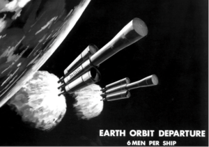
In 1969, Marshall Space Flight Director Wernher von Braun propose sending 12 men to Mars aboard two rockets, each propelled by three NERVA engines. This spacecraft would have measured 270 feet long and 100 feet wide across the three nuclear engine modules, with a mass of 800 tons, including 600 tons of liquid hydrogen propellant for the NERVA engines. The two outboard nuclear engine modules only would be used to inject the spacecraft onto its trans-Mars trajectory, after which they would separate from the spacecraft. The central nuclear engine module would continue with the manned spacecraft and be used to enter and leave Mars orbit and enter Earth orbit at the end of the mission. The mission would launch in November 1981 and land on Mars in August 1982.

Marshall 1969 NERVA mars missionNERVA-powered Mars spacecraft. Source: NASA / Monograph #21

NASA’s momentum for conducting a manned Mars mission by the 1980s was short-lived. Development of the super heavy lift Nova booster, which was intended to place about 250 tons to low Earth orbit (LEO), was never funded. Congress reduced NASA’s funding in the FY-69 budget, resulting in NASA ending production of the Saturn 5 heavy-lift booster rocket (about 100 tons to LEO) and cancelling Apollo missions after Apollo 17. This left NASA without the heavy-lift booster rocket needed to carry NERVA and/or assembled interplanetary spacecraft into orbit.

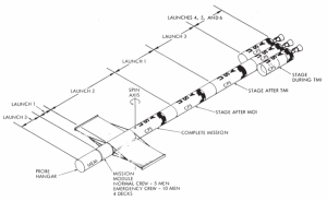
NASA persevered with chemical rocket powered Mars mission concepts until 1971. The final NASA concept vehicle from that era, looking much like von Braun’s 1969 nuclear-powered spacecraft, is shown below.

NASA 1971 mars concept

Source: NASA / Monograph #21

The 24-foot diameter modules would have required six Shuttle-derived launch vehicles (essentially the large center tank and the strap-in solid boosters, without the Space Shuttle itself) to deliver the various modules for assembly in orbit.

While no longer a factor in Mars mission planning, the nuclear rocket program was canceled in 1972. You can read a history of the U.S. nuclear thermal rocket program at the following links:

http://www.lanl.gov/science/NSS/issue1_2011/story4full.shtml

and,

http://ntrs.nasa.gov/archive/nasa/casi.ntrs.nasa.gov/19910017902.pdf

NASA budget realities in subsequent years, dictated largely by the cost of Space Shuttle and International Space Station development and operation, reduced NASA’s manned Mars efforts to a series of design studies, as described in the Monograph #21.

Science Applications International Corporation (SAIC) conducted manned Mars mission studies for NASA in 1984 and 1987. The latter mission design study was conducted in collaboration with astronaut Sally Ride’s August 1987 report, Leadership and America’s Future in Space. You can read this report at the following link.

http://history.nasa.gov/riderep/cover.htm

Details on the 1987 SAIC mission study are included in Chapter 8 of the Monograph #21. SAIC’s mission concept employed two chemically-fueled Mars spacecraft in “split/sprint” roles. An automated cargo-carrying spacecraft would be first to depart Earth. It would fly an energy-saving trajectory and enter Mars orbit carrying the fuel needed by the future manned spacecraft for its return to Earth. After the cargo spacecraft was in Mars orbit, the manned spacecraft would be launched on a faster “sprint” trajectory, taking about six months to get to Mars. With one month allocated for exploration of the Martian surface, total mission time would be on the order of 12 – 14 months.

President Obama’s FY-11 budget redirected NASA’s focus away from manned missions to the Moon and Mars. The result is that there are no current programs with near-term goals to establish a continuous U.S. presence on the Moon or conduct the first manned mission to Mars. Instead, NASA is engaged in developing hardware that will be used initially for a relatively near-Earth (but further out than astronauts have gone before) “asteroid re-direct mission.” NASA’s current vision for getting to Mars is summarized below.

  • In the 2020s, NASA will send astronauts on a year-long mission into (relatively near-Earth) deep space, verifying spacecraft habitation and testing our readiness for a Mars mission.
  • In the 2030s, NASA will send astronauts first to low-Mars orbit. This phase will test the entry, descent and landing techniques needed to get to the Martian surface and study what’s needed for in-situ resource utilization.
  • Eventually, NASA will land humans on Mars.

You can read NASA’s Journey to Mars Overview at the following link:

https://www.nasa.gov/content/journey-to-mars-overview

NASA’s current plans for getting to Mars don’t really sound like much of a plan to me. Think back to President Kennedy’s speech that outlined the national commitment needed to accomplish a lunar landing within the decade of the 1960s. There is no real sense of timeliness in NASA plans for getting to Mars.

Thinking back to the title of NASA’s Monograph #21, “Humans to Mars – Fifty Years of Mission Planning, 1950 – 2000,” I’d say that NASA is quite good at manned Mars mission planning, but woefully short on execution. I recognize that NASA’s ability to execute anything is driven by its budget. However, in 1969, Wernher von Braun thought the U.S. was about 12 years from being able to launch a nuclear-powered manned Mars mission in 1981. Now it seems we’re almost 20 years away, with no real concept for the spacecraft that will get our astronauts there and back.

Commercial plans for manned Mars exploration

Fortunately, the U.S. commercial aerospace sector seems more committed to conducting manned Mars missions than NASA. The leading U.S. contenders are Bigelow Aerospace and SpaceX. Let’s look at their plans.

Bigelow Aerospace

Bigelow is developing expandable structures that can be used to house various types of occupied spaces on manned Earth orbital platforms or on spacecraft destined for lunar orbital missions or long interplanetary missions. Versions of these expandable structures also can be used for habitats on the surface of the Moon, Mars, or elsewhere.

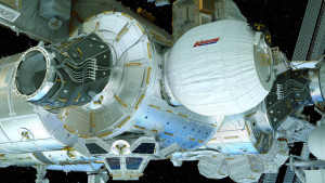
The first operational use of this type of expandable structure in space occurred on 26 May 2016, when the BEAM (Bigelow Expandable Activity Module) was deployed to its full size on the International Space Station (ISS). BEAM was expanded by air pressure from the ISS.

Bigelow BEAMBEAM installed in the ISS. Source: Bigelow Aerospace

You can view a NASA time-lapse video of BEAM deployment at the following link:

https://www.youtube.com/watch?v=QxzCCrj5ssE

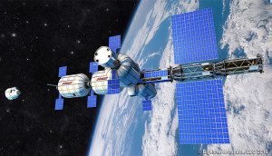
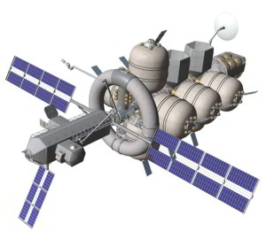
A large, complex space vehicle can be built with a combination of relatively conventional structures and Bigelow inflatable modules, as shown in the following concept drawing.

Bigelow spacecraft conceptSource: Bigelow Aerospace

A 2011 NASA concept named Nautilus-X, also making extensive use of inflatable structures, is shown in the following concept drawing. Nautilus is an acronym for Non-Atmospheric Universal Transport Intended for Lengthy United States Exploration.

NASA Nautilus-X-space-exploration-vehicle-concept-1

Source: NASA / NASA Technology Applications Assessment Team

SpaceX

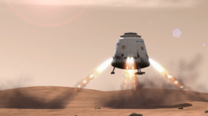
SpaceX announced that it plans to send its first Red Dragon capsule to Mars in 2018 to demonstrate the ability to land heavy loads using a combination of aero braking with the capsule’s ablative heat shield and propulsive braking using rocket engines for the final phase of landing.

Red Dragon landing on MarsSource: SpaceX

More details on the Red Dragon spacecraft are in a 2012 paper by Karcs, J. et al., entitled, “Red Dragon: Low-cost Access to the Surface of Mars Using Commercial Capabilities,” which you’ll find at the following link:

https://www.nas.nasa.gov/assets/pdf/staff/Aftosmis_M_RED_DRAGON_Low-Cost_Access_to_the_Surface_of_Mars_Using_Commercial_Capabilities.pdf

NASA is collaborating with SpaceX to gain experience with this landing technique, which NASA expects to employ in its own future Mars missions.

On 27 September 2016, SpaceX CEO Elon Musk unveiled his grand vision for colonizing Mars at the 67th International Astronautical Congress in Guadalajara, Mexico. You’ll find an excellent summary in the 29 September 2016 article by Dave Mosher entitled, “Elon Musk’s complete, sweeping vision on colonizing Mars to save humanity,” which you can read on the Business Insider website at the following link:

http://www.businessinsider.com/elon-musk-mars-speech-transcript-2016-9

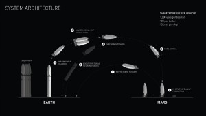
The system architecture for the SpaceX colonizing flights is shown in the following diagram. Significant features include:

  • 100 passengers on a one-way trip to Mars
  • Booster and spacecraft are reusable
  • No spacecraft assembly in orbit required.
  • The manned interplanetary vehicle is fueled with methane in Earth orbit from a tanker spacecraft.
  • The entire manned interplanetary vehicle lands on Mars. There is no part of the vehicle left orbiting Mars.
  • The 100 passengers disembark to colonize Mars
  • Methane fuel for the return voyage to Earth is manufactured on the surface of Mars.
  • The spacecraft returns to Earth for reuse on another mission.
  • Price per person for Mars colonists could be in the $100,000 to $200,000 range.

The Mars launcher for this mission would have a gross lift-off mass of 10,500 tons; 3.5 times the mass of NASA’s Saturn 5 booster for the Apollo Moon landing program.

SpaceX colonist architectureSource: SpaceX

 Terraforming Mars

Colonizing Mars will require terraforming to transform the planet so it can sustain human life. Terraforming the hostile environment of another planet has never been done before. While there are theories about how to accomplish Martian terraforming, there currently is no clear roadmap. However, there is a new board game named, “Terraforming Mars,” that will test your skills at using limited resources wisely to terraform Mars.

Nate Anderson provides a detailed introduction to this board game in his 1 October 2016 article entitled, “Terraforming Mars review: Turn the ‘Red Planet’ green with this amazing board game,” which you can read at the following link:

http://arstechnica.com/gaming/2016/10/terraforming-mars-review/?utm_source=howtogeek&utm_medium=email&utm_campaign=newsletter

71RW5ZM0bBL._SL1000_Source: Stronghold GamesTerraforming Mars gameboardSource: Nate Anderson / arsTECHNICA

Nate Anderson described the game as follows:

“In Terraforming Mars, you play one of several competing corporations seeking to terraform the Red Planet into a livable—indeed, hospitable—place filled with cows, dogs, fish, lichen, bacteria, grasslands, atmosphere, and oceans. That goal is achieved when three things happen: atmospheric oxygen rises to 14 percent, planetary temperature rises to 8°C, and all nine of the game’s ocean tiles are placed.

Real science rests behind each of these numbers. The ocean tiles each represent one percent coverage of the Martian surface; once nine percent of the planet is covered with water, Mars should develop its own sustainable hydrologic cycle. An atmosphere of 14 percent oxygen is breathable by humans (though it feels like a 3,000 m elevation on Earth). And at 8°C, water will remain liquid in the Martian equatorial zone.

Once all three milestones have been achieved, Mars has been successfully terraformed, the game ends, and scores are calculated.”

The players are competing corporations, each with limited resources. The game play evolves based how each player (corporation) chooses to spend their resources to build their terraforming engines (constrained by some rules of precedence), and the opportunities dealt to them in each round.

You can buy the game Terraforming Mars on Amazon.

So, before you sign up with SpaceX to become a Martian colonist, practice your skills at terraforming Mars. You’ll be in high demand as an expert terraformer when you get to Mars on a SpaceX colonist ship in the late 2020s.

Rosetta Spacecraft Lands on Comet 67P, Completing its 12-Year Mission

Peter Lobner

The European Space Agency (ESA) launched the Rosetta mission in 2004. After its long journey from Earth, followed by 786 days in orbit around comet 67P / Churyumov–Gerasimenko, the Rosetta spacecraft managers maneuvered the spacecraft out of its orbit and directed it to a “hard” landing on the “head” (the smaller lobe) of the comet.

Comet_67P_15_April_2015Comet 67P. Source: ESA – European Space Agency

The descent path, which started from an altitude of 19 km (11.8 miles), was designed to bring Rosetta down in the vicinity of active pits that had been observed from higher altitude earlier in the mission. ESA noted:

  • The descent gave Rosetta the opportunity to study the comet’s gas, dust and plasma environment very close to its surface, as well as take very high-resolution images.
  • Pits are of particular interest because they play an important role in the comet’s activity (i.e., venting gases to space).

The spacecraft impacted at a speed of about 90 cm/sec (about 2 mph) at 11:19 AM GMT (4:19 AM PDT) on 30 September 2016. I stayed up in California to watch the ESA’s live stream of the end of this important mission. I have to say that the live stream was not designed as a media event. As the landing approached, only a few close-up photos of the surface were shown, including the following photo taken from an altitude of about 5.7 km (3.5 miles).

Comet 67P 30Sep2016Source: ESA – European Space Agency

At the appointed moment, touchdown was marked by the loss of the telemetry signal from Rosetta. ESA said that the Rosetta spacecraft contained a message in many languages for some future visitor to 67P to find.

You can read the ESA’s press release on the end of the Rosetta mission at the following link:

http://www.esa.int/For_Media/Press_Releases/Mission_complete_Rosetta_s_journey_ends_in_daring_descent_to_comet

Some of the key Rosetta mission findings reported by ESA include:

  • Comet 67P likely was “born” in a very cold region of the protoplanetary nebula when the Solar System was still forming more than 4.5 billion years ago.
  • The comet’s two lobes probably formed independently, joining in a low-speed collision in the early days of the Solar System.
  • The comet’s shape influences its “seasons,” which are characterized by variations in dust moving across its surface and variations in the density and composition of the coma, the comet’s ‘atmosphere’.
  • Gases streaming from the comet’s nucleus include molecular oxygen and nitrogen, and water with a different ‘flavor’ than water in Earth’s oceans.
    • 67P’s water contains about three times more deuterium (a heavy form of hydrogen) than water on Earth.
    • This suggests that comets like Rosetta’s may not have delivered as much of Earth’s water as previously believed.
  • Numerous inorganic chemicals and organic compounds were detected by Rosetta (from orbit) and the Philae lander (on the surface). These include the amino acid glycine, which is commonly found in proteins, and phosphorus, a key component of DNA and cell membranes.

Analysis of data from the Rosetta mission will continue for several years. It will be interesting to see how our understanding of comet 67P and similar comets evolve in the years ahead.

For more information on the Rosetta mission, visit the ESA’s Rosetta website at the following link:

http://sci.esa.int/rosetta/

Also see my following postings: 24 August 2016, “Exploring Microgravity Worlds,” and 6 September 2016, “Philae Found in a Rocky Ditch on Comet 67P/Churyumov-Gerasimenko.”

Space-based Gravity Wave Detection System to be Deployed by ESA

Peter Lobner

The first detection of gravitational waves occurred on 14 September 2015 at the land-based Laser Interferometer Gravitational-Wave Observatory (LIGO). Using optical folding techniques, LIGO has an effective baseline of 1,600 km (994 miles). See my 16 December 2015 and 11 February 2016 posts for more information on LIGO and other land-based gravitational wave detectors.

Significantly longer baselines, and theoretically greater sensitivity can be achieved with gravitational wave detectors in space. Generically, such a space-based detector has become known as a Laser Interferometer Space Antenna (LISA). Three projects associated with space-based gravitational wave detection are:
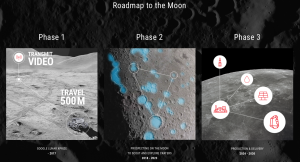
  • LISA (the project name predated the current generic usage of LISA)
  • LISA Pathfinder (a space-based gravitational wave detection technology demonstrator, not a detector)
  • Evolved LISA (eLISA)

These projects are discussed below.

The science being addressed by space-based gravitational wave detectors is discussed in the eLISA white paper, “The Gravitational Universe.” You can download this whitepaper, a 1-page summary, and related gravitational wave science material at the following link:

https://www.elisascience.org/whitepaper/

LISA

The LISA project originally was planned as a joint European Space Agency (ESA) and National Aeronautics & Space Administration (NASA) project to detect gravitational waves using a very long baseline, triangular interferometric array of three spacecraft.

Each spacecraft was to contain a gravitational wave detector sensitive at frequencies between 0.03 mHz and 0.1 Hz and have the capability to precisely measure its distances to the other two spacecraft forming the array. The equilateral triangular array, which was to measure about 5 million km (3.1 million miles) on a side, was expected to be capable of measuring gravitational-wave induced strains in space-time by precisely measuring changes of the separation distance between pairs of test masses in the three spacecraft. In 2011, NASA dropped out of this project because of funding constraints.

LISA Pathfinder

The LISA Pathfinder (LPF) is a single spacecraft intended to validate key technologies for space-based gravitational wave detection. It does not have the capability to detect gravity waves.

This mission was launched by ESA on 3 December 2015 and the spacecraft took station in a Lissajous orbit around the Sun-Earth L1 Lagrange point on 22 January 2016. L1 is directly between the Earth and the Sun, about 1.5 million km (932,000 miles) from Earth. An important characteristic of a Lissajous orbit is that the spacecraft will follow the L1 point without requiring any propulsion. This is important for minimizing external forces on the LISA Pathfinder experiment package. The approximate geometry of the Earth-Moon-Sun system and a representative spacecraft (not LPF, specifically) stationed at the L1 Lagrange point is shown in the following figure.

L1 Lagrange pointSource: Wikimedia Commons

The LISA Pathfinder’s mission is to validate the technologies used to shield two free-floating metal cubes (test masses), which form the core of the experiment package, from all internal and external forces that could contribute to noise in the gravitational wave measurement instruments. The on-board measurement instruments (inertial sensors and a laser interferometer) are designed to measure the relative position and orientation of the test masses, which are 38 cm (15 inches) apart, to an accuracy of less than 0.01 nanometers (10e-11 meters). This measurement accuracy is believed to be adequate for detecting gravitational waves using this technology on ESA’s follow-on mission, eLISA.

The first diagram below is an artist’s impression of the LISA Pathfinder technology package, showing the inertial sensors housing the test masses (gold) and the laser interferometer (middle platform). The second diagram provides a clearer view of the test masses and the laser interferometer.

LPF technology package 1

Source: ESA/ATG medialab, August 2015LPF technology package 2Source: ESA LISA Pathfinder briefing, 7 June 2016

You’ll find more general information in an ESA LISA Pathfinder overview, which you can download from NASA’s LISA website at the following link:

http://lisa.nasa.gov/Documentation/LISA-LPF-RP-0001_v1.1.pdf

LISA Pathfinder was commissioned and ready for scientific work on 1 March 2016. In a 7 June 2016 briefing, ESA reported very favorable performance results from LISA Pathfinder:

  • LPF successfully validated the technologies used in the local (in-spacecraft) instrument package (test masses, inertial sensors and interferometer).
  • LPF interferometer noise was a factor of 100 less than on the ground.
  • The measurement instruments can see femtometer motion of the test masses (LPF goal was picometer).
  • Performance is essentially at the level needed for the follow-on eLISA mission

You can watch this full (1+ hour) ESA briefing at the following link:

http://www.esa.int/Our_Activities/Space_Science/Watch_LISA_Pathfinder_briefing

eLISA

Evolved LISA, or eLISA, is ESA’s modern incarnation of the original LISA program described previously. ESA’s eLISA website home page is at the following link:

https://www.elisascience.org

As shown in the following diagrams, three eLISA spacecraft will form a very long baseline interferometric array that is expected to directly observe gravitational waves from sources anywhere in the universe. In essence, this array will be a low frequency microphone listening for the sounds of gravitational waves as they pass through the array.

eLISA constellation 1Source: ESAeLISA constellation 2Source: ESA

As discussed previously, gravity wave detection depends on the ability to very precisely measure the distance between test masses that are isolated from their environment but subject to the influence of passing gravitational waves. Measuring the relative motion of a pair of test masses is considerably more complex for eLISA than it was for LPF. The relative motion measurements needed for a single leg of the eLISA triangular array are:

  • Test mass 1 to Spacecraft 1
  • Spacecraft 1 to Spacecraft 2
  • Spacecraft 2 to Test Mass 2

This needs to be done for each of the three legs of the array.

LPF validated the technology for making the test mass to spacecraft measurement. Significant development work remains to be done on the spacecraft-to-spacecraft laser system that must take precise measurements at very long distances (5 million km, 3.1 million miles) of the relative motion between each pair of spacecraft.

In the 6 June 2016 LISA Pathfinder briefing, LPF and ESA officials indicated that an eLisa launch date is expected in the 2029 – 2032 time frame. Then it reaches its assigned position in a trailing heliocentric orbit, eLISA will be a remarkable collaborative technical achievement and a new window to our universe.

Breakthrough Starshot: Crashing Through Interstellar Dust and Gas Clouds at 0.2c

Peter Lobner

Yuri and Julia Milner founded the Breakthrough Initiatives in 2015 to explore the universe, seek scientific evidence of life beyond Earth, and encourage public debate from a planetary perspective. You’ll find an introduction to Breakthrough Initiatives at the following link:

https://breakthroughinitiatives.org/About

There are three initiatives described on this website:

Breakthrough Listen: This is a $100 million program of astronomical observations in search of evidence of intelligent life beyond Earth. It is by far the most comprehensive, intensive and sensitive search ever undertaken for artificial radio and optical signals. It includes a complete survey of the 1 million nearest stars, the plane and center of our galaxy, and the 100 nearest galaxies. All data will be open to the public.

Breakthrough Message: This is a $1 million competition to design a message representing Earth, life and humanity that could potentially be understood by another civilization.

Breakthrough Starshot: Yuri Milner and physicist Stephen Hawking announced the Breakthrough Starshot initiative on 12 April 2016. This is a $100 million research and engineering program with the goal of demonstrating proof-of-concept for a new technology: using laser light to accelerate ultra-light, unmanned, light sail spacecraft to 20% of the speed of light (0.2 c; 1.34 e+8 mph; 6.0e+7 meters/sec); and thereby enable a flyby mission to the nearest star system, Alpha Centauri, within a generation.

Breakthrough Starshot involves particularly intriguing engineering challenges. This initiative plans to launch many lightweight, light sail spacecraft from Earth and then individually accelerate each spacecraft to about 0.2 c using powerful terrestrial lasers. These lightweight spacecraft are expected to accelerate to about 0.2 c within a few minutes after laser propulsion begins. When the target speed has been reached, laser propulsion would be discontinued and the spacecraft will coast the rest of the way to its destination.

Solar sailing spacecraftThe Breakthrough Starshot light sail spacecraft after initial deployment, before the start of laser propulsion. Source: Breakthrough Starshot Initiative

Terrestrial laser power sourceThe terrestrial laser power source for the Breakthrough Starshot spacecraft. Source: Breakthrough Starshot Initiative

Breakthrough Starshot propelled by lasersBreakthrough Starshot light sail spacecraft being propelled by the terrestrial lasers. Source: Breakthrough Starshot Initiative

Spacecraft underwat toward deep spaceBreakthrough Starshot light sail spacecraft under power, heading for deep space. Source: Breakthrough Starshot Initiative
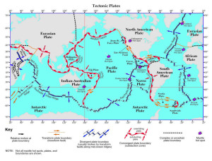
You can watch a short video on the Breakthrough Starshot spacecraft at the following link:

https://www.youtube.com/watch?v=wMkWGN1G6Kg

A detailed video (1hr 16 min) on this initiative, with discussions by Stephen Hawking and Freeman Dyson, is at the following link:

https://www.youtube.com/watch?v=0cVQwDdYF4w

While the concept of a terrestrial laser-powered, ultra-light, light sail spacecraft is intriguing, the reality of flying through interstellar space at a speed of 0.2 c relative to low-density cosmic dust and gas along the route may raise daunting engineering challenges related to spacecraft survivability. The approach being taken by the Breakthrough Starshot initiative will be to launch many light sail spacecraft to provide redundancy and improve the likelihood of mission success.

How much damage could a grain of space dust inflict on a spacecraft? The worst case would be for the spacecraft to absorb all the kinetic energy from the collision.

Wikipedia reports that cosmic dust falling to Earth has been studied and found to be composed of grains with masses between 10−16 kg and 10−4 kg.

The classical Newtonian equation for kinetic energy (Ek) will yield an adequate approximation of the kinetic energy transferred in an impact at a speed of 0.2 c:

Ek = ½ mv2

where m is the mass of the projectile, and v2 is the square of the velocity of the projectile.
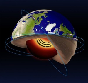
The maximum kinetic energy deposited by a cosmic dust particle with an “average” mass, 10−10 kg, is estimated to be:

Ek = 0.5 (1e-10 kg)(3.6e+15 m2/sec2) = 1.8e+5 kg-m2/sec2 = 180,000 Joules

This is about 40 times the maximum kinetic energy of a projectile fired from a 12-gauge shotgun. That would be quite damaging, so hopefully there is a very low probability of encountering cosmic dust of this mass. In this case, that v2 term in the equation has a very bad effect on kinetic energy.
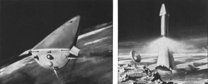
In comparison, the maximum kinetic energy deposited by a cosmic dust particle at the low end of the mass range, 10−16 kg, is estimated to be:

Ek = 0.5 (1e-16 kg)(3.6e+15 m2/sec2) = 1.8e-1 kg-m2/sec2 = 0.18 Joules

This is in the approximate kinetic energy range of a small projectile fired from an airsoft (paintball) type gun. If the spacecraft isn’t damaged, the momentum transfer, even from smaller impacts such as this, may be sufficient to alter the course of the spacecraft. As you can see, cosmic dust can be quite hazardous to fast moving spacecraft.

You can read more about the Breakthrough Starshot initiative at the following links:

arsTECHNICA, 23 August 2016: “Just how dangerous is it to travel at 20% the speed of light?

http://arstechnica.com/science/2016/08/could-breakthrough-starshots-ships-survive-the-trip/

National Geographic, 13 April 2016: “Is the New $100 Million ‘Starshot’ for Real?”

http://news.nationalgeographic.com/2016/04/160413-fast-facts-stephen-hawking-starshot-space/