On 20 April 2020, the U.S. Geological Survey (USGS) released the first-ever comprehensive digital geologic map of the Moon. The USGS described this high-resolution map as follows:
“The lunar map, called the ‘Unified Geologic Map of the Moon,’ will serve as the definitive blueprint of the moon’s surface geology for future human missions and will be invaluable for the international scientific community, educators and the public-at-large.”
Color-coded orthographic projections of the “Unified Geologic Map of the Moon” showing the geology of the Moon’s near side (left) and far side (right). Source: NASA/GSFC/USGS
This remarkable mapping product is the culmination of a decades-long project that started with the synthesis of six Apollo-era (late 1960s – 1970s) regional geologic maps that had been individually digitized and released in 2013 but not integrated into a single, consistent lunar map.
This intermediate mapping product was updated based on data from the following more recent lunar satellite missions:
The Lunar Reconnaissance Orbiter Camera (LROC) is a system of three cameras that capture high resolution black and white images and moderate resolution multi-spectral images of the lunar surface: http://lroc.sese.asu.edu
Topography for the north and south poles was supplemented with Lunar Orbiter Laser Altimeter (LOLA) data: https://lola.gsfc.nasa.gov
The final product is a seamless, globally consistent map that is available in several formats: geographic information system (GIS) format at 1:5,000,000-scale, PDF format at 1:10,000,000-scale, and jpeg format.
At the following link, you can download a large zip file (310 Mb) that contains a jpeg file (>24 Mb) with a Mercator projection of the lunar surface between 57°N and 57°S latitude, two polar stereographic projections of the polar regions from 55°N and 55°S latitudes to the poles, and a description of the symbols and color coding used in the maps.
These high-resolution maps are great for exploring the lunar surface in detail. A low-resolution copy (not suitable for browsing) is reproduced below.
For more information on the Unified Geologic Map of the Moon, refer to the paper by C. M. Fortezzo, et al., “Release of the digital Unified Global Geologic Map of the Moon at 1:5,000,000-scale,” which is available here: https://www.hou.usra.edu/meetings/lpsc2020/pdf/2760.pdf
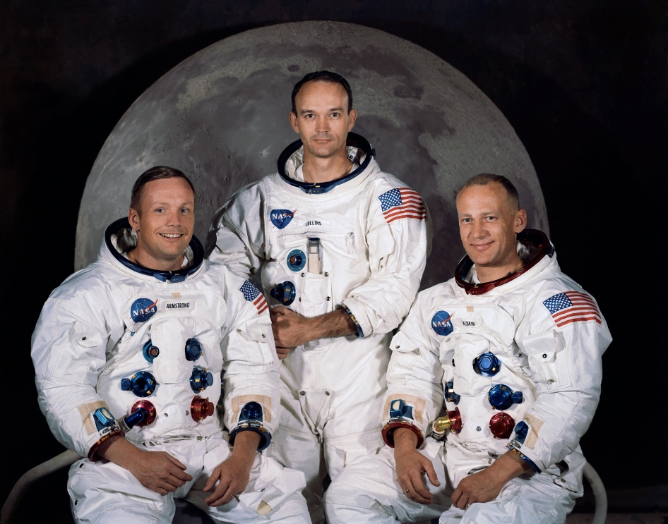
On July 16th, 1969, 13:32:00 UTC, the Saturn V launch vehicle, SA-506, lifted off from Launch Pad 39-A at Kennedy Space Center, Florida on the Apollo 11 mission with astronauts Neil Armstrong (Mission commander), Michael Collins (Command Module pilot) and Edwin (Buzz) Aldrin (Lunar Module pilot).
L to R: Neil Armstrong, Michael Collins & Buzz Aldrin. Source: NASA
Apollo 11 insignia: Eagle with wings outstretched holding an olive branch above the Moon with Earth in the background.Source: NASA via Wikipedia
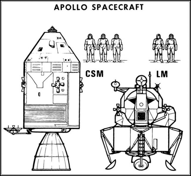
The Apollo spacecraft consisted of three modules:
The three-person Command Module (CM), named Columbia, was the living quarters for the three-person crew during most of the lunar landing mission.
The Service Module (SM) contained the propulsion system, electrical fuel cells, consumables storage tanks (oxygen, hydrogen) and various service / support systems.
The two-person, two-stage Lunar Module (LM), named Eagle, would make the Moon landing with two astronauts and return them to the CM.
The LM’s descent stage (bottom part of the LM with the landing legs) remained on the lunar surface and served as the launch pad for the ascent stage (upper part of the LM with the crew compartment). Only the 4.9 ton CM was designed to withstand Earth reentry conditions and return the astronauts safely to Earth.
General configuration of the Apollo spacecraft. The “CSM” is the combined Command Module and Service Module. Source: NASA
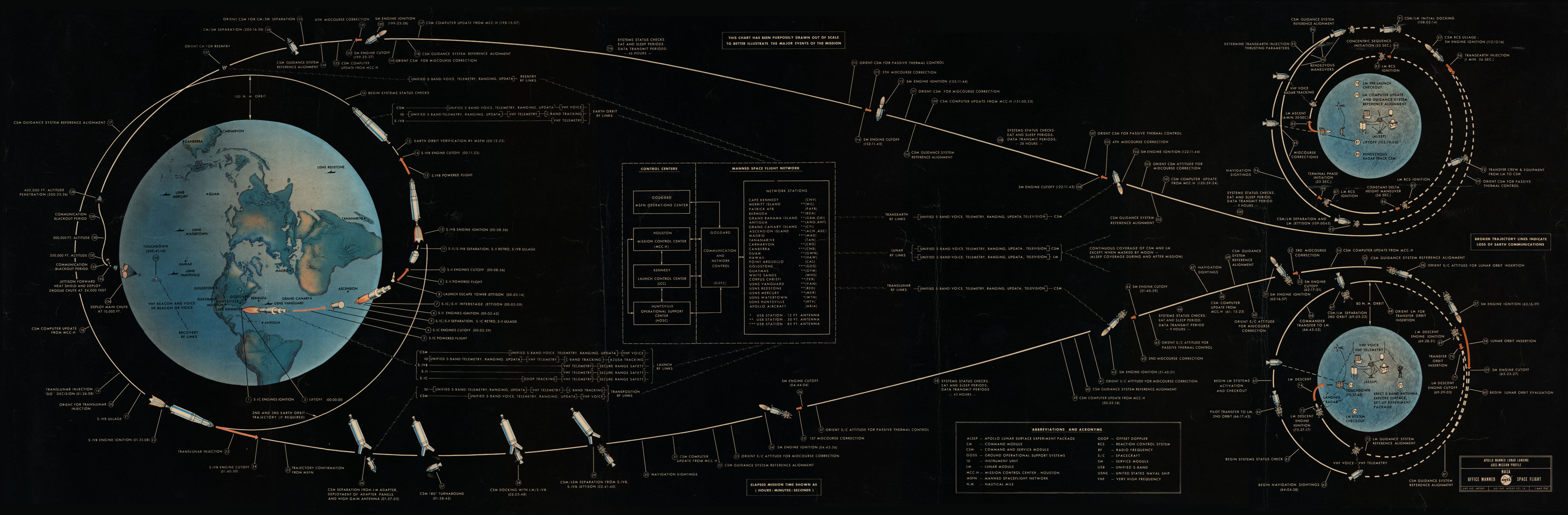
From its initial low Earth parking orbit, Apollo 11 flew a direct trans-lunar trajectory to the Moon, inserting into lunar orbit about 76 hours after liftoff. The Apollo 11 mission profile to and from the Moon is shown in the following diagram, and is described in detail here: https://www.mpoweruk.com/Apollo_Moon_Shot.htm
Source: NASA
Neil Armstrong and Buzz Aldrin landed the Eagle LM in the Sea of Tranquility on 20 July 1969, at 20:17 UTC (about 103 hours elapsed time since launch), while Michael Collins remained in a near-circular lunar orbit aboard the CSM. Neil Armstrong characterized the lunar surface at the Tranquility Base landing site with the observation, “it has a stark beauty all its own.”
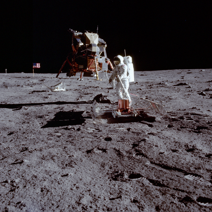
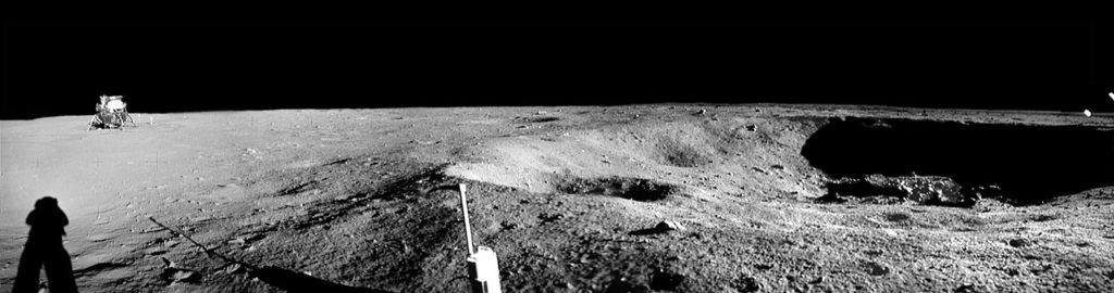
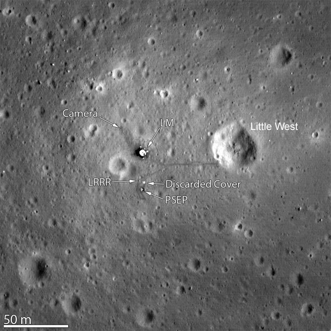
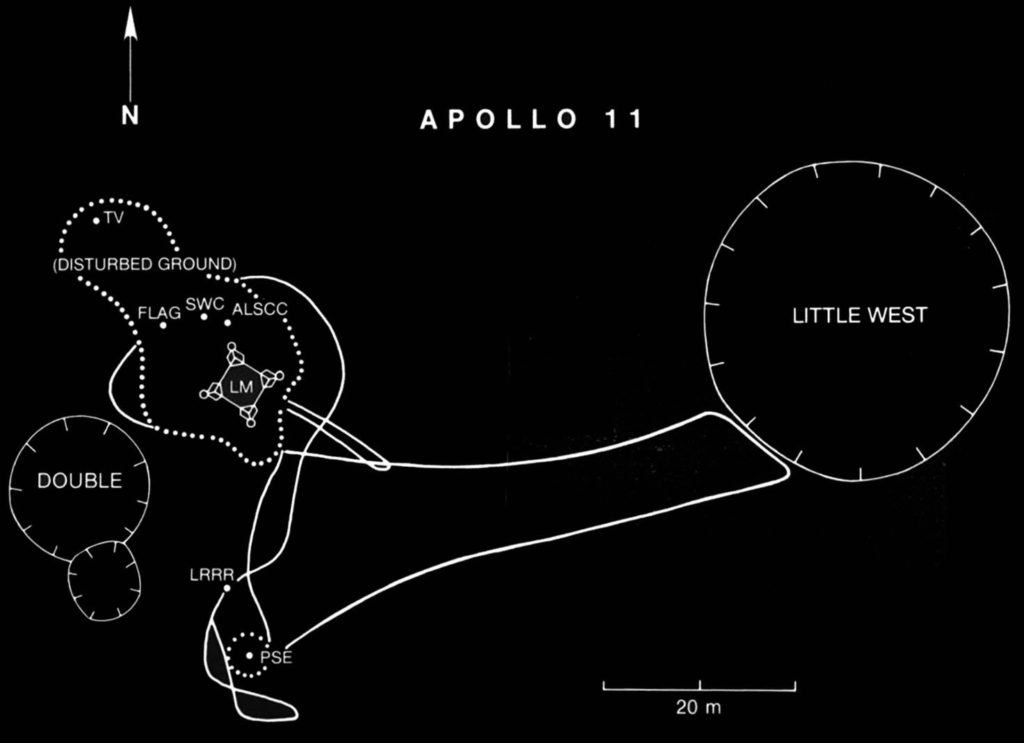
In the two and a half hours they spent on the lunar surface, Armstrong and Aldrin collected 21.55 kg (47.51 lb) of rock samples, took photographs and set up the Passive Seismic Experiment Package (PSEP) and the Laser Ranging RetroReflector (LRRR), which would be left behind on the Moon. The PSEP provided the first lunar seismic data, returning data for three weeks after the astronauts left, and the LRRR allows precise distance measurements to be collected to this day. Neil Armstrong made an unscheduled jaunt to Little West crater, about 50 m (164 feet) east of the LM, and provided the first view into a lunar crater.
Apollo 11 PSEP in the foreground with astronaut Buzz Aldrin and the LRRR behind it, then the Eagle LM, the American flag, and the TV camera on the left horizon beyond the American flag. Source: NASANeil Armstrong’s photo showing the Eagle LM from Little West crater (33 meters in diameter). Source: NASAApollo 11 landing site captured from 24 km (15 miles) above the surface by NASA’s Lunar Reconnaissance Orbiter (LRO). Source: adapted from NASA Goddard/Arizona State UniversityApollo 11 “traverse” map. Source: NASA via Smithsonian https://airandspace.si.edu/
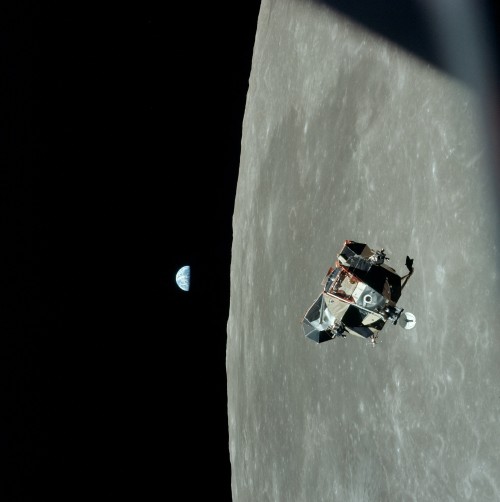
Armstrong and Aldrin departed the Moon on 21 July 1969 at 17:54 UTC in the ascent stage of the Eagle LM and then rendezvoused and docked with Collins in the CSM about 3-1/2 hours later.
LM Eagle ascent stage with Armstrong and Aldrin approaching the CSM Columbia piloted by Collins. Source: NASA
After discarding the ascent stage, the CSM main engine was fired and Apollo 11 left lunar orbit on 22 July 1969 at 04:55:42 UTC and began its trans-Earth trajectory. As the Apollo spacecraft approached Earth, the SM was jettisoned.
The CM reentered the Earth’s atmosphere and landed in the North Pacific on 24 July 1969 at 16:50:35 UTC. The astronauts and the Apollo 11 spacecraft were recovered by the aircraft carrier USS Hornet. President Nixon personally visited and congratulated the astronauts while they were still in quarantine aboard the USS Hornet. You can watch a video of this meeting here:
Mankind’s first lunar landing mission was a great success.
Postscript to the first Moon landing
A month after returning to Earth, the Apollo 11 astronauts were given a ticker tape parade in New York City, then termed as the largest such parade in the city’s history.
New York City ticker tape parade for the Apollo 11 astronauts. Source: NASA / Bill Taub
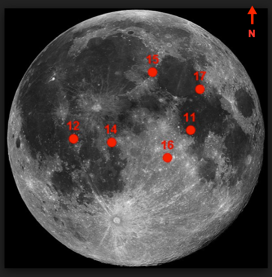
There were a total of six Apollo lunar landings (Apollo 11, 12, 14, 15, 16, and 17), with the last mission, Apollo 17, returning to Earth on 19 December 1972. Their landing sites are shown in the following graphic.
The Apollo landing sites. Source: NASA
In the past 46+ years since Apollo 17, there have been no manned missions to the Moon by the U.S. or any other nation.
Along with astronaut John Glenn, the first American to fly in Earth orbit, the three Apollo 11 astronauts were awarded the New Frontier Congressional Gold Medal in the Capitol Rotunda on 16 November 2011. This is the Congress’ highest civilian award and expression of national appreciation for distinguished achievements and contributions.
Neil Armstrong died on 25 August 2012 at the age of 82.
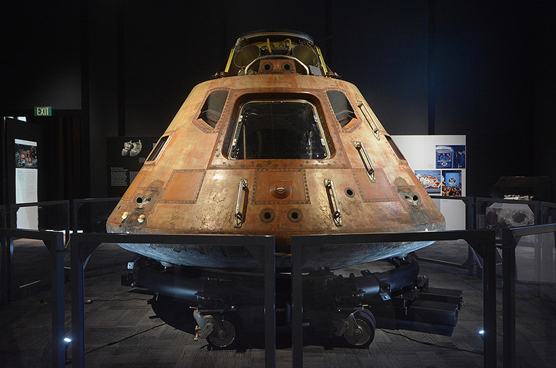
The Apollo 11 command module Columbia was physically transferred to the Smithsonian Institution in 1971 and has been on display for decades at the National Air and Space Museum on the mall in Washington D.C. For the 50th anniversary of the Apollo 11 mission, Columbia will be on display at The Museum of Flight in Seattle, as the star of the Smithsonian Institution’s traveling exhibition, “Destination Moon: The Apollo 11 Mission.” You can get a look at this exhibit at the following link: http://www.collectspace.com/news/news-041319a-destination-moon-seattle-apollo.html
The Apollo 11 command module Columbia at The Museum of Flight in Seattle. Source: collectSPACE
After years of changing priorities under the Bush and Obama administrations, NASA’s current vision for the next U.S. manned lunar landing mission is named Artemis, after the Greek goddess of hunting and twin sister of Apollo. NASA currently is developing the following spaceflight systems for the Artemis mission:
The Space Launch System (SLS) heavy launch vehicle.
A manned “Gateway” station that will be placed in lunar orbit, where it will serve as a transportation node for lunar landing vehicles and manned spacecraft for deep space missions.
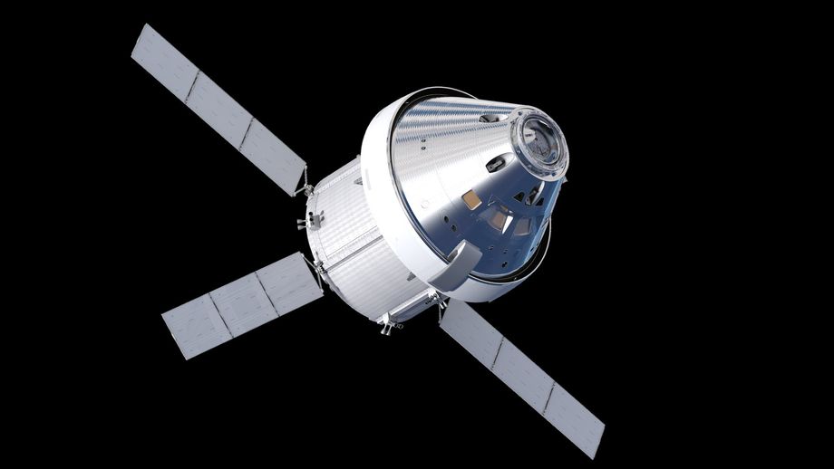
The Orion multi-purpose manned spacecraft, which will deliver astronauts from Earth to the Gateway, and also can be configured for deep space missions.
Lunar landing vehicles, which will shuttle between the Gateway and destinations on the lunar surface.
The Orion spacecraft is functionally comparable to the Apollo command and service modules. Source: NASA
While NASA has a tentative goal of returning humans to the Moon by 2024, the development schedules for the necessary Artemis systems may not be able to meet this ambitious schedule. The landing site for the Artemis mission will be in the Moon’s south polar region. NASA administrator Jim Bridenstine has stated that Artemis will deliver the first woman to the Moon.
Robert C. Seamens, Jr., “Project Apollo – The Tough Decisions,” NASA Monographs in Aerospace History Number 37, NASA SP-2007-4537, 2007; https://history.nasa.gov/monograph37.pdf
Ian A. Crawford, “The Scientific Legacy of Apollo,” Astronomy and Geophysics (Vol. 53, pp. 6.24-6.28), December 2012; https://arxiv.org/pdf/1211.6768.pdf
Roger D. Launis, “Apollo’s Legacy: Perspectives on the Moon Landings,” Smithsonian Books, 14 May 2019, ISBN-13: 978-1588346490
Neil Armstrong, Michael Collins & Edwin Aldrin, “First on the Moon,” William Konecky Assoc., 15 October 2002, ISBN-13: 978-1568523989
Michael Collins, “Flying to the Moon: An Astronaut’s Story,” Farrar, Straus and Giroux (BYR); 3 edition, 28 May 2019, ISBN-13: 978-0374312022
Michael Collins, “Carrying the Fire: An Astronaut’s Journeys: 50th Anniversary Edition Anniversary Edition,” Farrar, Straus and Giroux, 16 April 2019, ISBN-13: 978-0374537760
Edwin Aldrin, “Return to Earth,” Random House; 1st edition, 1973, ISBN-13: 978-0394488325
After the failure of Israel’s Beresheet spacecraft to execute a soft landing on the Moon in April 2019, India is the next new contender for lunar soft landing honors with their Chandrayaan-2 spacecraft. We’ll take a look at the Chandrayaan-2 mission in this post.
1. Background: India’s Chandrayaan-1 mission to the Moon
India’s first mission to the Moon, Chandrayaan-1, was a mapping mission designed to operate in a circular (selenocentric) polar orbit at an altitude of 100 km (62 mi). The Chandrayaan-1 spacecraft, which had an initial mass of 1,380 kg (3,040 lb), consisted of two modules, an orbiter and a Moon Impact Probe (MIP). Chandrayaan-1 carried 11 scientific instruments for chemical, mineralogical and photo-geologic mapping of the Moon. The spacecraft was built in India by the Indian Space Research Organization (ISRO), and included instruments from the USA, UK, Germany, Sweden and Bulgaria.
Chandrayaan-1 was launched on 22 October 2008 from the Satish Dhawan Space Center (SDSC) in Sriharikota on an “extended” version of the indigenous Polar Satellite Launch Vehicle designated PSLV-XL. Initially, the spacecraft was placed into a highly elliptical geostationary transfer orbit (GTO), and was sent to the Moon in a series of orbit-increasing maneuvers around the Earth over a period of 21 days. A lunar transfer maneuver enabled the Chandrayaan-1 spacecraft to be captured by lunar gravity and then maneuvered to the intended lunar mapping orbit. This is similar to the five-week orbital transfer process used by Israel’s Bersheet lunar spacecraft to move from an initial GTO to a lunar circular orbit.
The goal of MIP was to make detailed measurements during descent using three instruments: a radar altimeter, a visible imaging camera, and a mass spectrometer known as Chandra’s Altitudinal Composition Explorer (CHACE), which directly sampled the Moon’s tenuous gaseous atmosphere throughout the descent. On 14 November 2008, the 34 kg (75 lb) MIP separated from the orbiter and descended for 25 minutes while transmitting data back to the orbiter. MIP’s mission ended with the expected hard landing in the South Pole region near Shackelton crater at 85 degrees south latitude.
In May 2009, controllers raised the orbit to 200 km (124 miles) and the orbiter mission continued until 28 August 2009, when communications with Earth ground stations were lost. The spacecraft was “found” in 2017 by NASA ground-based radar, still in its 200 km orbit.
Numerous reports have been published describing the detection by the Chandrayaan-1 mission of water in the top layers of the lunar regolith. The data from CHACE produced a lunar atmosphere profile from orbit down to the surface, and may have detected trace quantities of water in the atmosphere. You’ll find more information on the Chandrayaan-1 mission at the following links:
2. India’s upcoming Chandrayaan-2 mission to the Moon
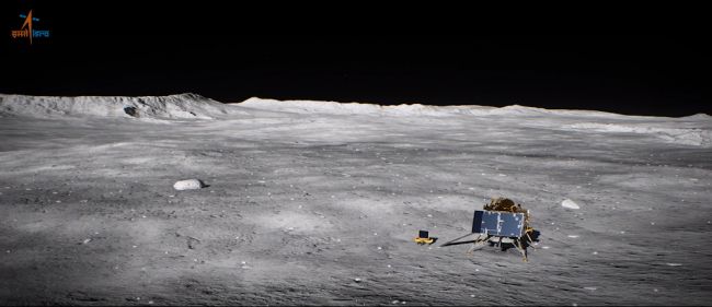
Chandrayaan-2 was launched on 22 July 2019. After achieving a 100 km (62 mile) circular polar orbit around the Moon, a lander module will separate from the orbiting spacecraft and descend to the lunar surface for a soft landing, which currently is expected to occur in September 2019, after a seven-week journey to the Moon. The target landing area is in the Moon’s southern polar region, where no lunar lander has operated before. A small rover vehicle will be deployed from the lander to conduct a 14-day mission on the lunar surface. The orbiting spacecraft is designed to conduct a one-year mapping mission.
Artist’s illustration of India’s lunar lander and the small rover vehicle on the surface of the moon. Source: ISRO
The launch vehicle
India will launch Chandrayaan-2 using the medium-lift Geosynchronous Satellite Launch Vehicle Mark III (GSLV Mk III) developed and manufactured by ISRO. As its name implies, GSLV Mk III was developed primarily to launch communication satellites into geostationary orbit. Variants of this launch vehicle also are used for science missions and a human-rated version is being developed to serve as the launch vehicle for the Indian Human Spaceflight Program.
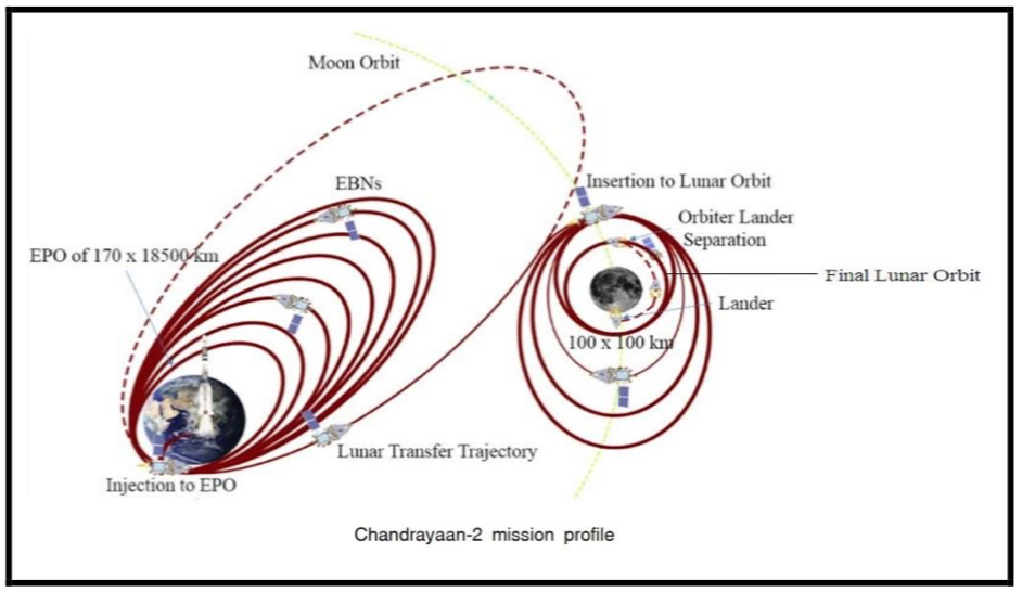
The GSLV III launch vehicle will place the Chandrayaan-2 spacecraft into an elliptical parking orbit (EPO) from which the spacecraft will execute orbital transfer maneuvers comparable to those successfully executed by Chandrayaan-1 on its way to lunar orbit in 2008. The Chandrayaan-2 mission profile is shown in the following graphic. You’ll find more information on the GSLV Mk III on the ISRO website at the following link: https://www.isro.gov.in/launchers/gslv-mk-iii
Source: ISRO
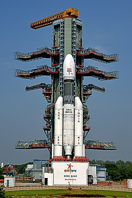
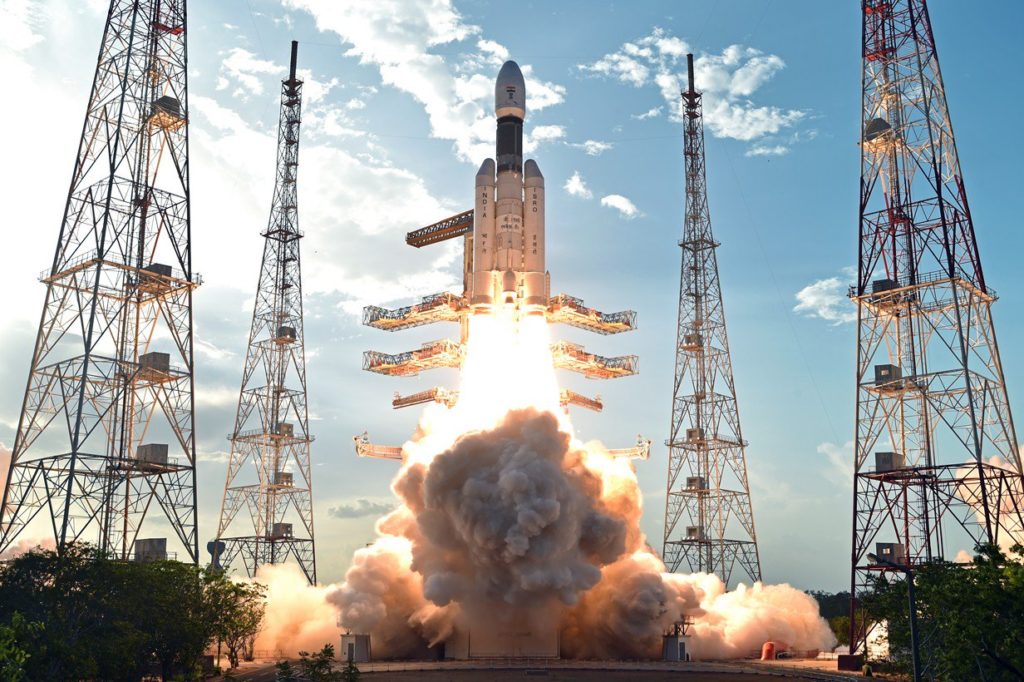
GSLV Mk III D2 on the launch pad at SDSC for the launchof the GSAT-29 communications satellite in 2018.Source: ISRO via Wikipedia
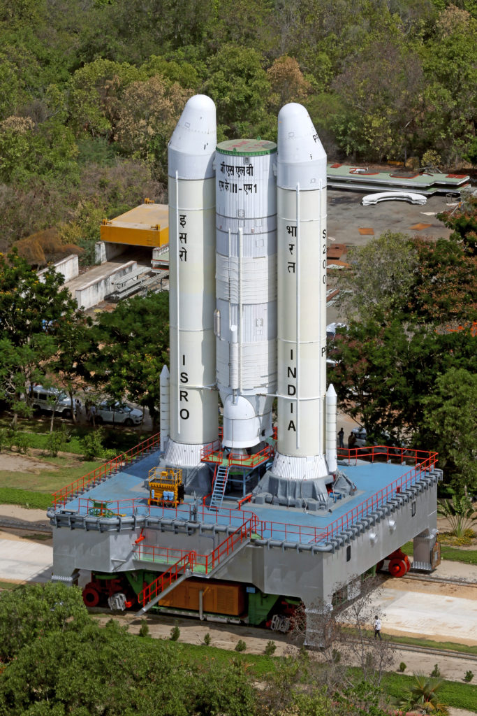
GSLV Mk III D1 lifting off from the SDSCwith the GSAT-19 communications satellite in 2017.Source: ISRO via WikipediaTransporting the partially integrated GSLV MkIII M1 launch vehicle for the Chandrayaan-2 mission on the Mobile Launch Pedestal. Source: ISRO
The spacecraft
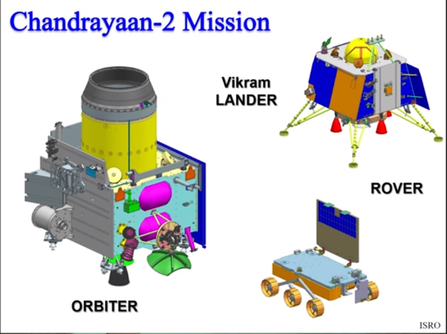
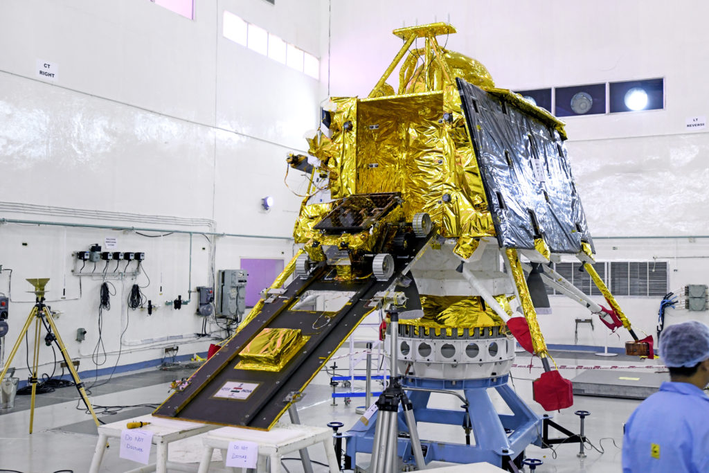
Chandrayaan-2 builds on the design and operating experience from the previous Chandrayaan-1 mission. The new spacecraft developed by ISRO has an initial mass of 3,877 kg (8,547 lb). It consists of three modules: an Orbiter Craft (OC) module, the Vikram Lander Craft (LC) module, and the small Pragyan rover vehicle, which is carried by the LC. The three modules are shown in the following diagram.
Three spacecraft modules (not to scale). Source: ISRO
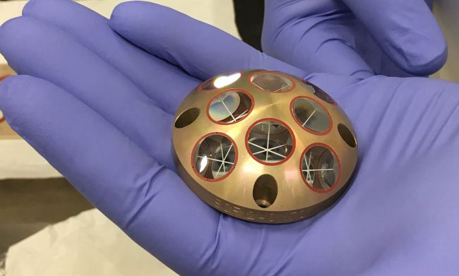
Chandrayaan-2 carries 13 Indian payloads — eight on the orbiter, three on the lander and two on the rover. In addition, the lander carries a passive Laser Retroreflector Array (LRA) provided by NASA.
Laser Retroreflector Array (LRA). Source: ISRO
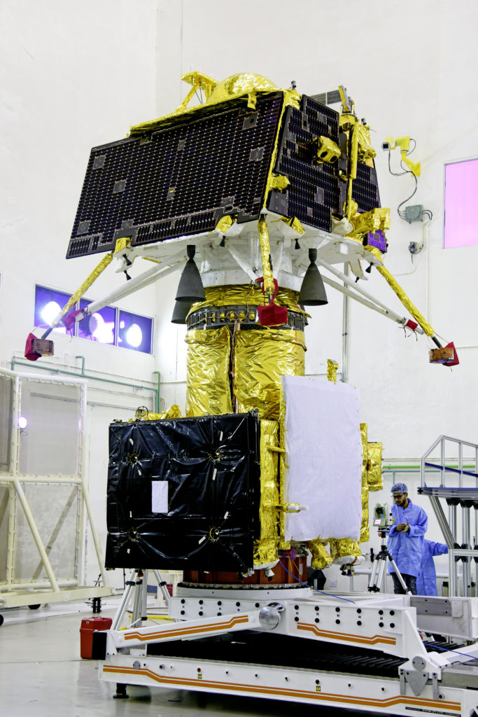
The OC and the LC are stacked together within the payload fairing of the launch vehicle and remain stacked until the LC separates in lunar orbit and starts its descent to the lunar surface.
Orbiter (bottom) & lander (top) in stacked configuration. Source: ISRO
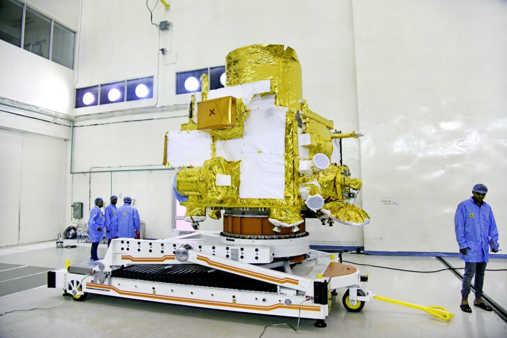
The solar-powered orbiter is designed for a one-year mission to map lunar surface characteristics (chemical, mineralogical, topographical), probe the lunar surface for water ice, and map the lunar exosphere using the CHACE-2 mass spectrometer. The orbiter also will relay communication between Earth and Vikram lander.
The orbiter. Source: ISRO
The solar-powered Vikram lander weighs 1,471 kg (3,243 lb). The scientific instruments on the lander will measure lunar seismicity, measure thermal properties of the lunar regolith in the polar region, and measure near-surface plasma density and its changes with time.
The Vikram lander with the Pragyan rover on the ramp.Source: ISRO
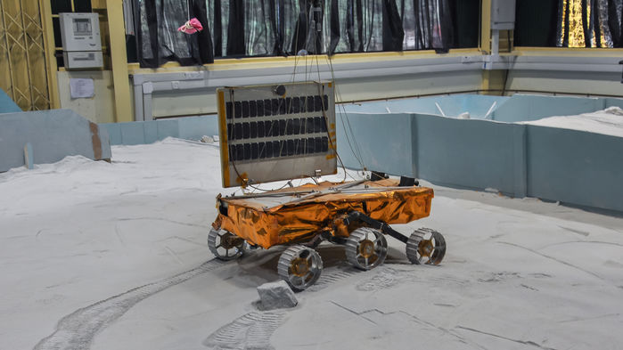
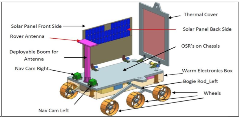
The 27 kg (59.5 lb) six-wheeled Pragyan rover, whose name means “wisdom” in Sanskrit, is solar-powered and capable of traveling up to 500 meters (1,640 feet) on the lunar surface. The rover can communicate only with the Vikram lander. It is designed for a 14-day mission on the lunar surface. It is equipped with cameras and two spectroscopes to study the elemental composition of lunar soil.
Rover during testing. Source: ISRORover details. Source: ISRO
You’ll find more information on the spacecraft in the 2018 article by V. Sundararajan, “Overview and Technical Architecture of India’s Chandrayaan-2 Mission to the Moon,” at the following link:
Best wishes to the Chandrayaan-2 mission team for a successful soft lunar landing and long-term lunar mapping mission.
Update 2 December 2019: Vikram lander crashed on the Moon
After a 48-day transit following launch, and an apparently nominal descent toward the lunar surface, communications with the Vikram lander were lost on 6 September 2019, when the spacecraft was at an altitude of about 2 km (1.2 miles), with just seconds remaining before the planned landing. Communications with the Chandrayaan orbiter continued after communications was lost with the Vikram lander. More details on India’s failed landing attempt are in the 25 November 2019 article on the Space.com website here: https://www.space.com/india-admits-moon-lander-crash.html
1. Overview of US military optical reconnaissance satellite programs
The National Reconnaissance Office (NRO) is responsible for developing and operating space reconnaissance systems and conducting intelligence-related activities for US national security. NRO developed several generations of classified Keyhole (KH) military optical reconnaissance satellites that have been the primary sources of Earth imagery for the US Department of Defense (DoD) and intelligence agencies. NRO’s website is here:
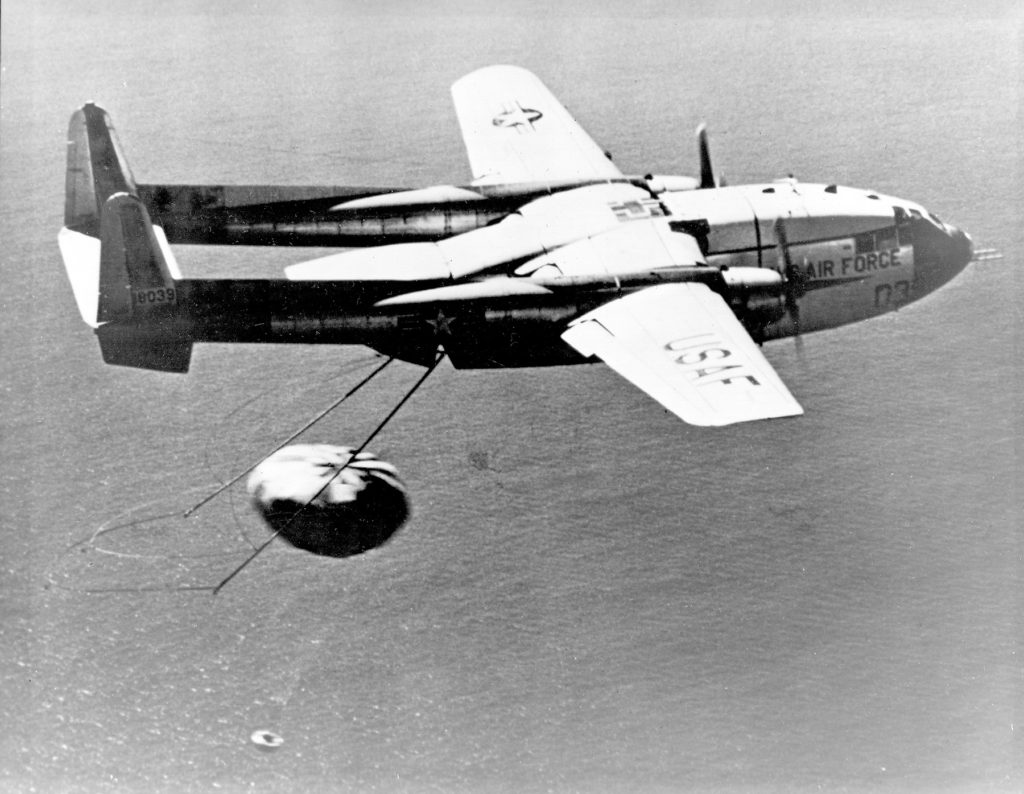
NRO’s early generations of Keyhole satellites were placed in low Earth orbits, acquired the desired photographic images on film during relatively short-duration missions, and then returned the film to Earth in small reentry capsules for airborne recovery. After recovery, the film was processed and analyzed. The first US military optical reconnaissance satellite program, code named CORONA, pioneered the development and refinement of the technologies, equipment and systems needed to deploy an operational orbital optical reconnaissance capability. The first successful CORONA film recovery occurred on 19 August 1960.
Specially modified US Air Force C-119J aircraft recovers a CORONA film canister in flight. Source: US Air Force
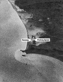
First reconnaissance picture taken in orbit and successfully recovered on Earth; taken on 18 August 1960 by a CORONA KH-1 satellite dubbed Discoverer 14. Image shows the Mys Shmidta airfield in the Chukotka region of the Russian Arctic, with a resolution of about 40 feet (12.2 meters). Source: Wikipedia
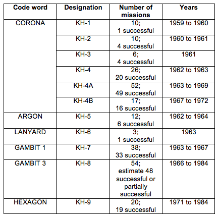
Keyhole satellites are identified by a code word and a “KH” designator, as summarized in the following table.
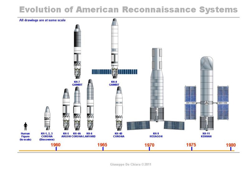
In 1976, NRO deployed its first electronic imaging optical reconnaissance satellite known as KENNEN KH-11 (renamed CRYSTAL in 1982), which eventually replaced the KH-9, and brought an end to reconnaissance satellite missions requiring film return. The KH-11 flies long-duration missions and returns its digital images in near real time to ground stations for processing and analysis. The KH-11, or an advanced version sometimes referred to as the KH-12, is operational today.
US film-return reconnaissance satellites from KH-1 to KH-9 shown to scale with the KH-11 electronic imaging reconaissance satellite. Credit: Giuseppe De Chiara and The Space Review.
Geospatial intelligence, or GEOINT, is the exploitation and analysis of imagery and geospatial information to describe, assess and visually depict physical features and geographically referenced activities on the Earth. GEOINT consists of imagery, imagery intelligence and geospatial information. Satellite imagery from Keyhole reconnaissance satellites is an important information source for national security-related GEOINT activities.
The National Geospatial-Intelligence Agency (NGA), which was formed in 2003, has the primary mission of collecting, analyzing, and distributing GEOINT in support of national security. NGA’s predecessor agencies, with comparable missions, were:
National Imagery and Mapping Agency (NIMA), 1996 – 2003
National Photographic Interpretation Center (NPIC), a joint project of the Central Intelligence Agency (CIA) and DoD, 1961 – 1996
2. The advent of the US civilian Earth observation programs
Collecting Earth imagery from orbit became an operational US military capability more than a decade before the start of the joint National Aeronautics & Space Administration (NASA) / US Geological Survey (USGS) civilian Landsat Earth observation program. The first Landsat satellite was launched on 23 July 1972 with two electronic observing systems, both of which had a spatial resolution of about 80 meters (262 feet).
Since 1972, Landsat satellites have continuously acquired low-to-moderate resolution digital images of the Earth’s land surface, providing long-term data about the status of natural resources and the environment. Resolution of the current generation multi-spectral scanner on Landsat 9 is 30 meters (98 feet) in visible light bands.
3. Declassification of certain military reconnaissance satellite imagery
All military reconnaissance satellite imagery was highly classified until 1995, when some imagery from early defense reconnaissance satellite programs was declassified. The USGS explains:
“The images were originally used for reconnaissance and to produce maps for U.S. intelligence agencies. In 1992, an Environmental Task Force evaluated the application of early satellite data for environmental studies. Since the CORONA, ARGON, and LANYARD data were no longer critical to national security and could be of historical value for global change research, the images were declassified by Executive Order 12951 in 1995”
Additional sets of military reconnaissance satellite imagery were declassified in 2002 and 2011 based on extensions of Executive Order 12951.
The declassified imagery is held by the following two organizations:
The original film is held by the National Archives and Records Administration (NARA).
Duplicate film held in the USGS Earth Resources Observation and Science (EROS) Center archive is used to produce digital copies of the imagery for distribution to users.
The declassified military satellite imagery available in the EROS archive is summarized below:
USGS EROS Archive – Declassified Satellite Imagery – 1 (1960 to 1972)
This set of photos, declassified in 1995, consists of more than 860,000 images of the Earth’s surface from the CORONA, ARGON, and LANYARD satellite systems.
CORONA image resolution improved from 40 feet (12.2 meters) for the KH-1 to about 6 feet (1.8 meters) for the KH-4B.
KH-5 ARGON image resolution was about 460 feet (140 meters).
KH-6 LANYARD image resolution was about 6 feet (1.8 meters).
USGS EROS Archive – Declassified Satellite Imagery – 2 (1963 to 1980)
This set of photos, declassified in 2002, consists of photographs from the KH-7 GAMBIT surveillance system and KH-9 HEXAGON mapping program.
KH-7 image resolution is 2 to 4 feet (0.6 to 1.2 meters). About 18,000 black-and-white images and 230 color images are available.
The KH-9 mapping camera was designed to support mapping requirements and exact positioning of geographical points. Not all KH-9 satellite missions included a mapping camera. Image resolution is 20 to 30 feet (6 to 9 meters); significantly better than the 98 feet (30 meter) resolution of LANDSAT imagery. About 29,000 mapping images are available.
USGS EROS Archive – Declassified Satellite Imagery – 3 (1971 to 1984)
This set of photos, declassified in 2011, consists of more photographs from the KH-9 HEXAGON mapping program. Image resolution is 20 to 30 feet (6 to 9 meters).
4. Example applications of declassified military reconnaissance satellite imagery
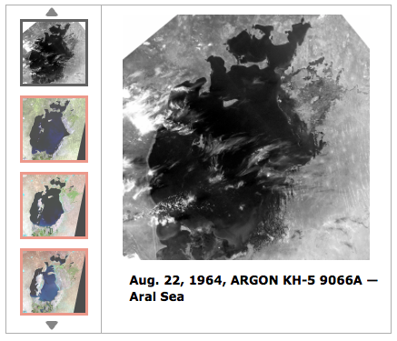
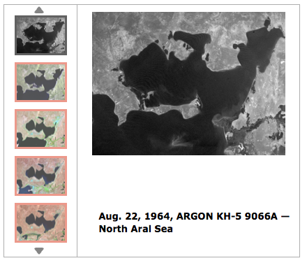
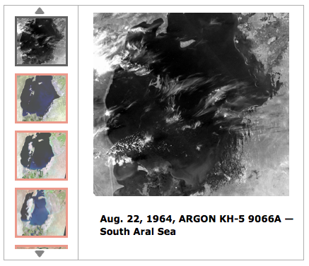
The declassified military reconnaissance satellite imagery provides views of the Earth starting in the early 1960s, more than a decade before civilian Earth observation satellites became operational. The military reconnaissance satellite imagery, except from ARGON KH-5, is higher resolution than is available today from Landsat civilian earth observation satellites. The declassified imagery is an important supplement to other Earth imagery sources. Several examples applications of the declassified imagery are described below.
4.1 Assessing Aral Sea depletion
USGS reports: “The Aral Sea once covered about 68,000 square kilometers, a little bigger than the U.S. state of West Virginia. It was the 4th largest lake in the world. It is now only about 10% of the size it was in 1960…..In the 1990s, a dam was built to prevent North Aral water from flowing into the South Aral. It was rebuilt in 2005 and named the Kok-Aral Dam…..The North Aral has stabilized but the South Aral has continued to shrink and become saltier. Up until the 1960s, Aral Sea salinity was around 10 grams per liter, less than one-third the salinity of the ocean. The salinity level now exceeds 100 grams per liter in the South Aral, which is about three times saltier than the ocean.”
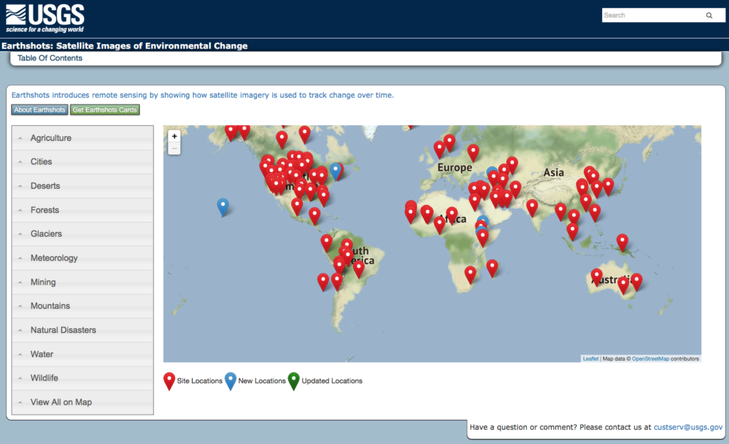
On the USGS website, the “Earthshots: Satellite Images of Environmental Change” webpages show the visible changes at many locations on Earth over a 50+ year time period. The table of contents to the Earthshots webpages is shown below and is at the following link: http:// https://earthshots.usgs.gov/earthshots/
USGS Earthshots Table of Contents
For the Aral Sea region, the Earthshots photo sequences start with ARGON KH-5 photos taken in 1964. Below are three screenshots of the USGS Earthshots pages showing the KH-5 images for the whole the Aral Sea, the North Aral Sea region and the South Aral Sea region. You can explore the Aral Sea Earthshots photo sequences at the following link: https://earthshots.usgs.gov/earthshots/node/91#ad-image-0-0
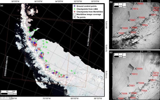
4.2 Assessing Antarctic ice shelf condition
In a 7 June 2016 article entitled, ”Spy satellites reveal early start to Antarctic ice shelf collapse,” Thomas Sumner reported:
“Analyzing declassified images from spy satellites, researchers discovered that the downhill flow of ice on Antarctica’s Larsen B ice shelf was already accelerating as early as the 1960s and ’70s. By the late 1980s, the average ice velocity at the front of the shelf was around 20 percent faster than in the preceding decades,….”
Satellite images taken by the ARGON KH-5 satellite have revealed how the accelerated movement that triggered the collapse of the Larsen B ice shelf on the east side of the Antarctic Peninsula began in the 1960s. The declassified images taken by the satellite on 29 August 1963 and 1 September 1963 are pictured right. Source: Daily Mail, 10 June 2016
4.3 Assessing Himalayan glacier condition
In a 19 June 2019 paper “Acceleration of ice loss across the Himalayas over the past 40 years,” the authors, reported on the use of HEXAGON KH-9 mapping camera imagery to improve their understanding of trends affecting the Himalayan glaciers from 1975 to 2016:
“Himalayan glaciers supply meltwater to densely populated catchments in South Asia, and regional observations of glacier change over multiple decades are needed to understand climate drivers and assess resulting impacts on glacier-fed rivers. Here, we quantify changes in ice thickness during the intervals 1975–2000 and 2000–2016 across the Himalayas, using a set of digital elevation models derived from cold war–era spy satellite film and modern stereo satellite imagery.”
“The majority of the KH-9 images here were acquired within a 3-year interval (1973–1976), and we processed a total of 42 images to provide sufficient spatial coverage.”
“We observe consistent ice loss along the entire 2000-km transect for both intervals and find a doubling of the average loss rate during 2000–2016.”
“Our compilation includes glaciers comprising approximately 34% of the total glacierized area in the region, which represents roughly 55% of the total ice volume based on recent ice thickness estimates.”
3-D image of the Himalayas derived from HEXAGON KH-9 satellite mapping photographs taken on December 20, 1975.Source: J. M. Maurer/LDEO
4.4 Discovering archaeological sites
A. CORONA Atlas Project
The Center for Advanced Spatial Technologies, a University of Arkansas / U.S. Geological Survey collaboration, has undertaken the CORONA Atlas Project using military reconnaissance satellite imagery to create the “CORONA Atlas & Referencing System”. The current Atlas focuses on the Middle East and a small area of Peru, and is derived from 1,024 CORONA images taken on 50 missions. The Atlas contains 833 archaeological sites.
“In regions like the Middle East, CORONA imagery is particularly important for archaeology because urban development, agricultural intensification, and reservoir construction over the past several decades have obscured or destroyed countless archaeological sites and other ancient features such as roads and canals. These sites are often clearly visible on CORONA imagery, enabling researchers to map sites that have been lost and to discover many that have never before been documented. However, the unique imaging geometry of the CORONA satellite cameras, which produced long, narrow film strips, makes correcting spatial distortions in the images very challenging and has therefore limited their use by researchers.”
Screenshot of the CORONA Atlas showing regions in the Middle East with data available.
CAST reports that they have “developed methods for efficient
orthorectification of CORONA imagery and now provides free public access to our imagery database for non-commercial use. Images can be viewed online and full resolution images can be downloaded in NITF format.”
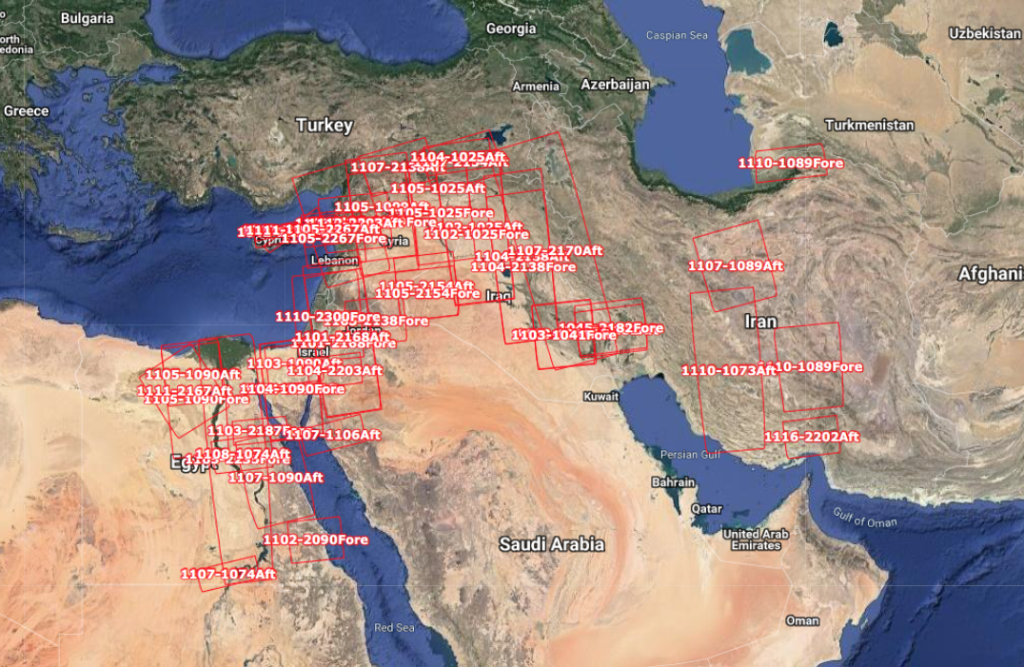
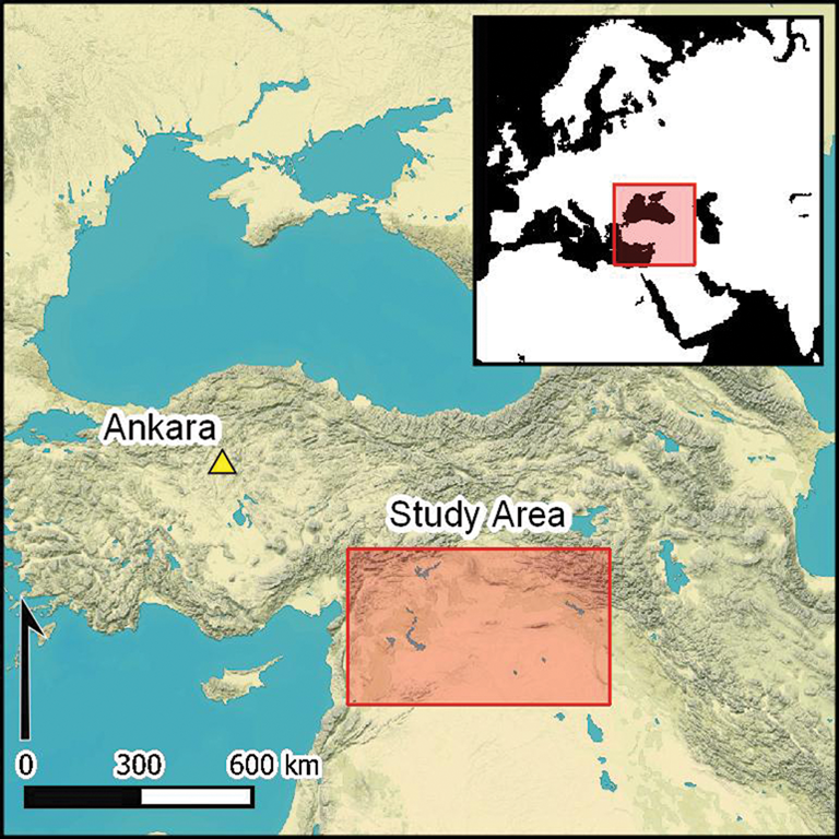
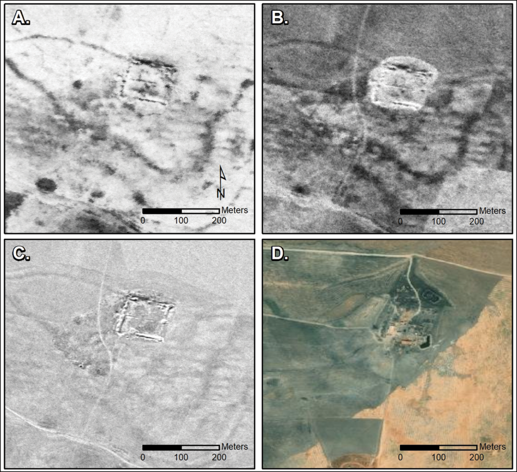
In October 2023, a team from Dartmouth College published a paper that described their recent discovery of 396 Roman-era forts using declassified CORONA and HEXAGON spy satellite imagery of regions of Syria, Iraq and nearby “fertile crescent” territories of the eastern Mediterranean. The study area is shown in the following map. A previous aerial survey of the area in 1934 had identified 116 other forts in the same region.
Dartmouth study area. Source: J. Casana, et al. (26 October 2023)
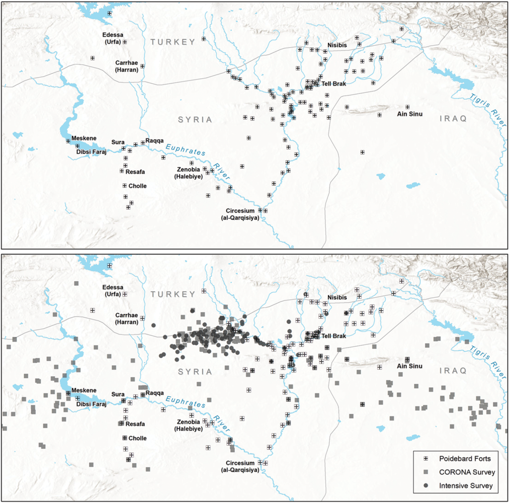
The authors noted, “Perhaps the most significant realization from our work concerns the spatial distribution of the forts across the landscape, as this has major implications for our understanding of their intended purpose as well as for the administration of the eastern Roman frontier more generally.”
Comparison of the distribution of forts documented in the 1934 aerial survey (top)and forts found recently on declassified satellite imagery (bottom).Source: Figure 9, J. Casana, et al. (26 October 2023)
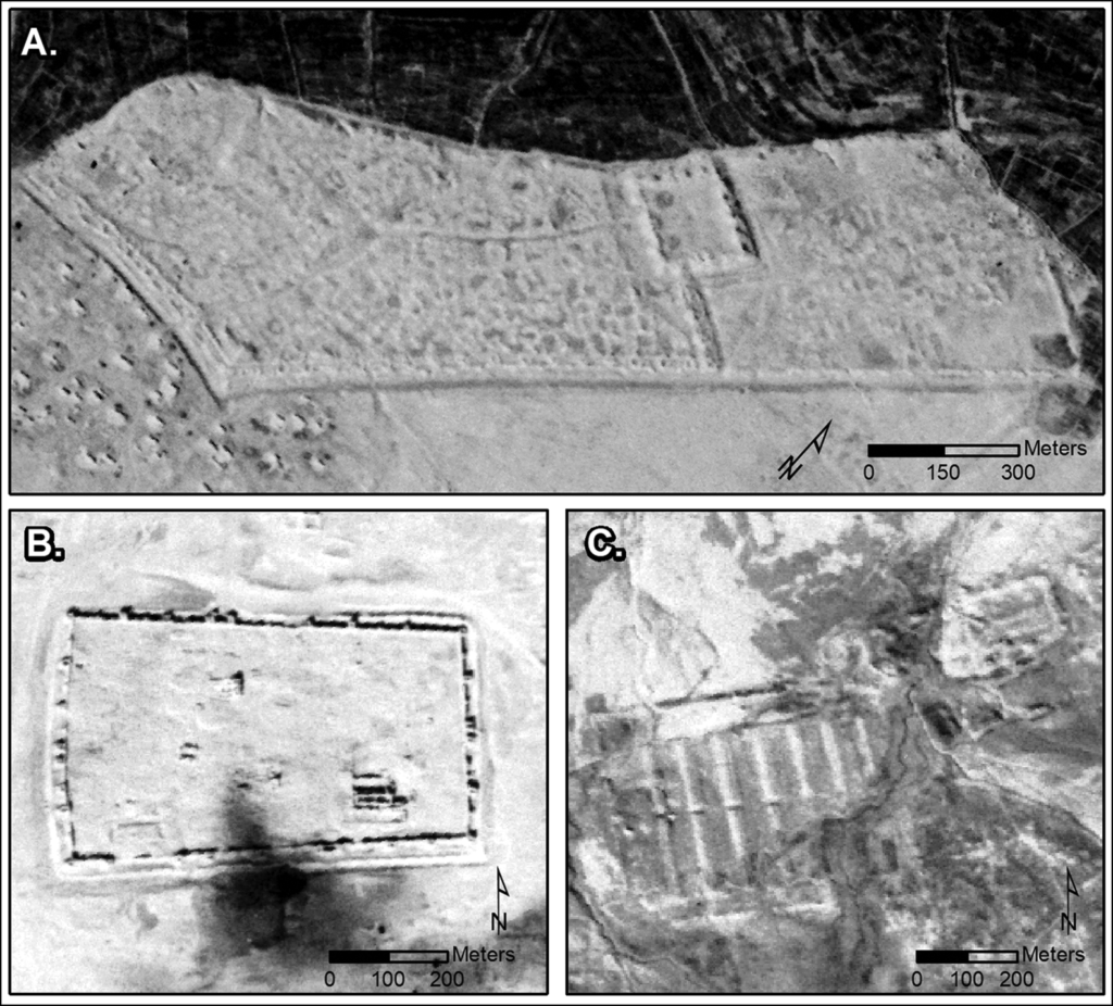
Examples of the new forts identified by the Dartmouth team in satellite imagery are shown in the following figures.
CORONA images showing three major sites: (A) Sura (NASA1401); (B) Resafa (NASA1398); and (C) Ain Sinu (CRN999).Source: Figure 3, J. Casana, et al. (26 October 2023)
Castellum at Tell Brak site in multiple images: (A) CORONA (1102, 17 December 1967); (B) CORONA (1105, 4 November 1968); (C) HEXAGON (1204, 17 November 1974); and (D) modern satellite imagery. Source: Figure 4, J. Casana, et al. (26 October 2023)
The teams paper concludes: “Finally, the discovery of such a large number of previously undocumented ancient forts in this well-studied region of the Near East is a testament to the power of remote-sensing technologies as transformative tools in contemporary archaeological research.”
4.5 Conducting commercial geospatial analytics over a broader period of time
The firm Orbital Insight, founded in 2013, is an example of commercial firms that are mining geospatial data and developing valuable information products for a wide range of customers. Orbital Insight reports:
“Orbital Insight turns millions of images into a big-picture understanding of Earth. Not only does this create unprecedented transparency, but it also empowers business and policy decision makers with new insights and unbiased knowledge of socio-economic trends. As the number of Earth-observing devices grows and their data output expands, Orbital Insight’s geospatial analytics platform finds observational truth in an interconnected world. We map out and quantify the world’s complexities so that organizations can make more informed decisions.”
“By applying artificial intelligence to satellite, UAV, and other geospatial data sources, we seek to discover and quantify societal and economic trends on Earth that are indistinguishable to the human eye. Combining this information with terrestrial data, such as mobile and location-based data, unlocks new sources of intelligence.”
5. Additional reading related to US optical reconnaissance satellites
You’ll find more information on the NRO’s film-return, optical reconnaissance satellites (KH-1 to KH-9) at the following links:
Robert Perry, “A History of Satellite Reconnaissance,” Volumes I to V, National Reconnaissance Office (NRO), various dates 1973 – 1974; released under FOIA and available for download on the NASA Spaceflight.com website, here: https://forum.nasaspaceflight.com/index.php?topic=20232.0
The firm Northrop Grumman Innovation Systems (formerly Orbital ATK, and before that, Orbital Sciences Corporation) was the first to develop a commercial, air-launched rocket capable of placing payloads into Earth orbit. Initial tests of their modest-size Pegasus launch vehicle were made in 1990 from the NASA B-52 that previously had been used as the “mothership” for the X-15 experimental manned space plane and many other experimental vehicles.
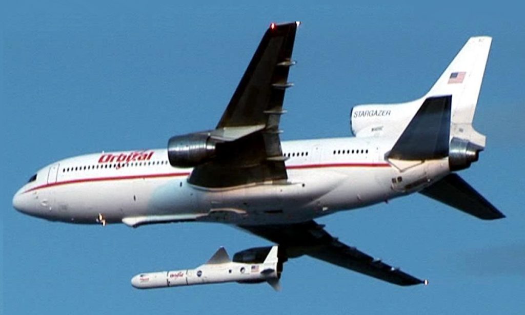
Since 1994, Orbital ATK has been using a specially modified civilian Lockheed L-1011 TriStar, a former airliner renamed Stargazer, as a mothership to carry a Pegasus launch vehicle to high altitude, where the rocket is released to fly a variety of missions, including carrying satellites into orbit. With a Pegasus XL as its payload (launch vehicle + satellite), Stargazer is lifting up to 23,130 kg (50,990 pounds) to a launch point at an altitude of about 12.2 km (40,000 feet).
Orbital ATK’s Pegasus XL rocket released from Stargazer. Source: NASA / http://mediaarchive.ksc.nasa.gov
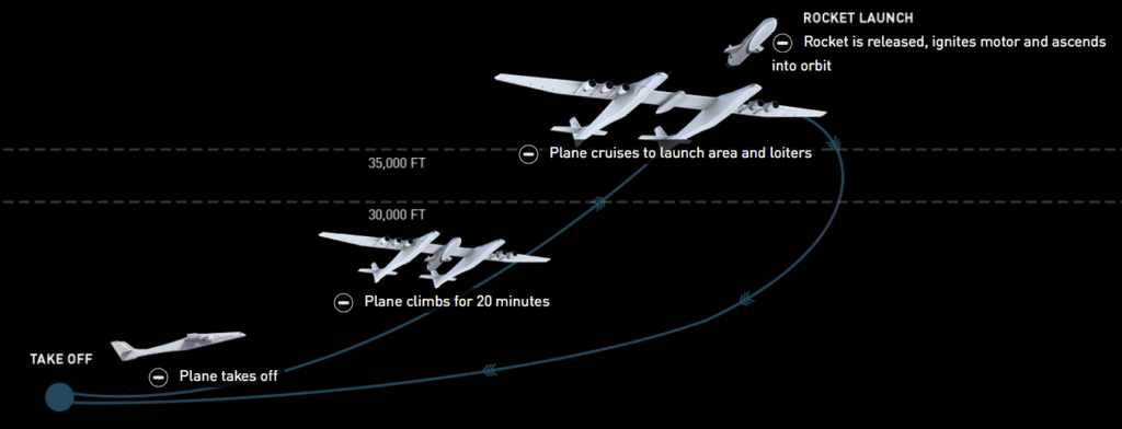
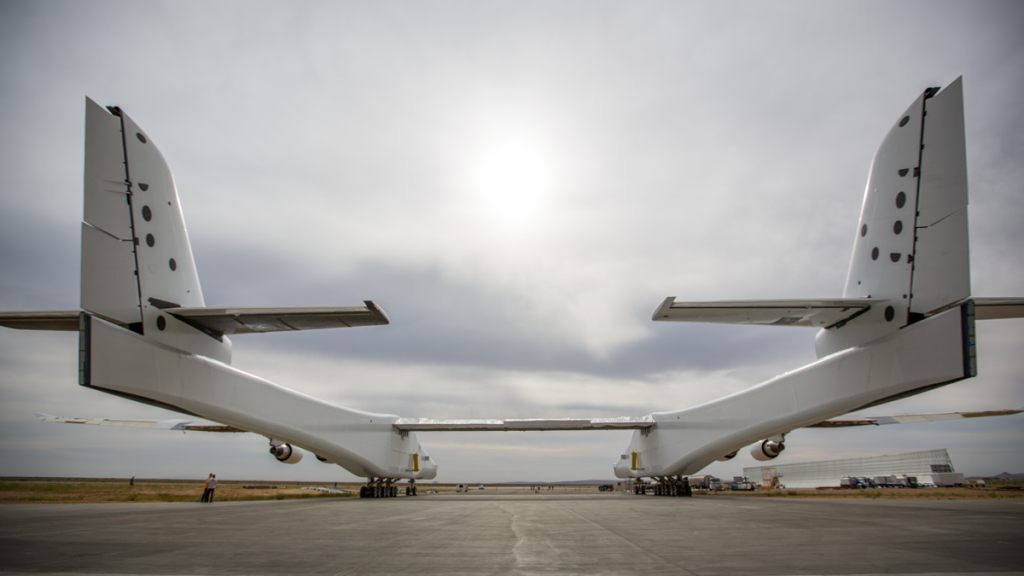
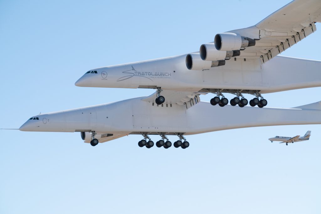
Paul Allen’s firm Stratolaunch Systems Corporation (https://www.stratolaunch.com) was founded in 2011 to take this air-launch concept to a new level with their giant, twin-fuselage, six-engine Stratolaunch carrier aircraft. The aircraft has a wingspan of 385 feet (117 m), which is the greatest of any aircraft ever built, a length of 238 feet (72.5 m), and a height of 50 feet (15.2 m) to the top of the vertical tails. The empty weight of the aircraft is about 500,000 pounds (226,796 kg). It is designed for a maximum takeoff weight of 1,300,000 pounds (589,670 kg), leaving about 550,000 pounds (249,486 kg) for its payload and the balance for fuel and crew. It will be able to carry multiple launch vehicles on a single mission to a launch point at an altitude of about 35,000 feet (10,700 m). A mission profile for the Stratolaunch aircraft is shown in the following diagram.
Typical air-launch mission profile. Source: Stratolaunch Systems
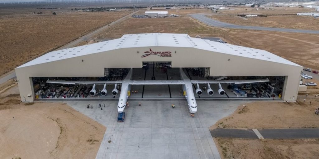
Stratolaunch rollout – 2017
Built by Scaled Composites, the Stratolaunch aircraft was unveiled on 31 May 2017 when it was rolled out at the Mojave Air and Space Port in Mojave, CA. Following is a series of photos from Stratolaunch Systems showing the rollout.
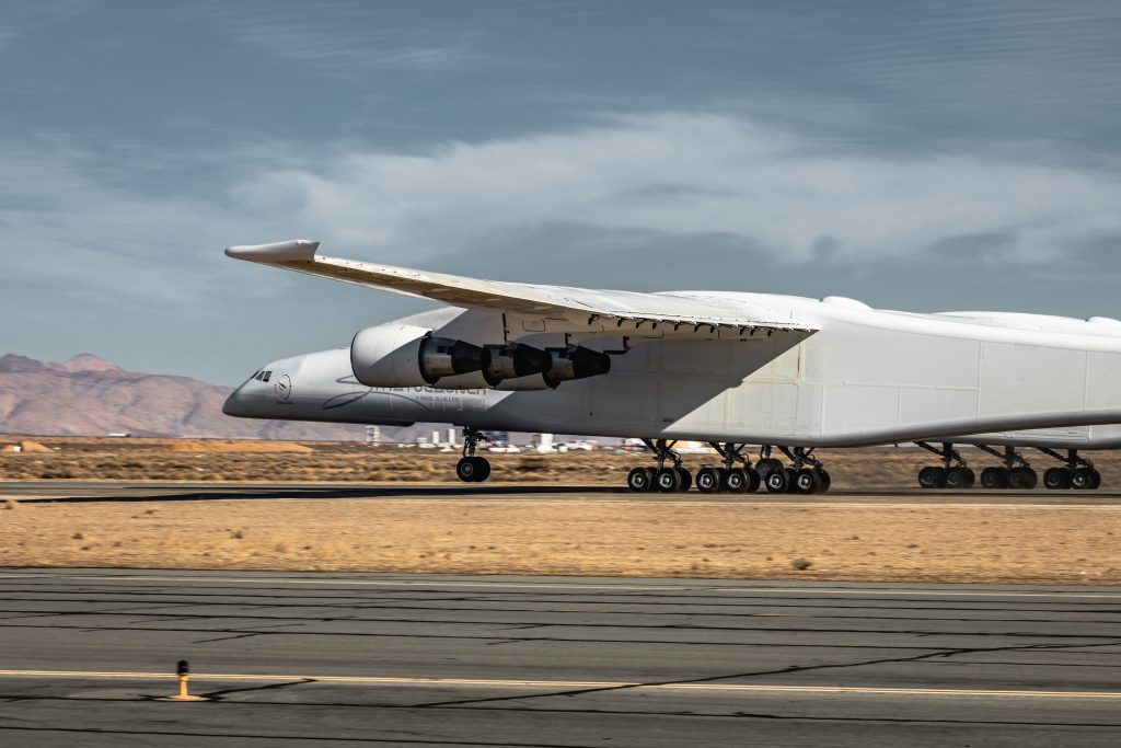
Stratolaunch ground tests – 2017 to 2019
Ground testing of the aircraft systems started after rollout. By mid-September 2017, the first phase of engine testing was completed, with all six Pratt & Whitney PW4000 turbofan engines operating for the first time. The first low-speed ground tests conducted in December 2017 reached a modest speed of 25 knot (46 kph). By January 2019, the high-speed taxi tests had reached a speed of about 119 knots (220 kph) with the nose wheel was off the runway, almost ready for lift off. Following is a series of photos from Stratolaunch Systems showing the taxi tests.
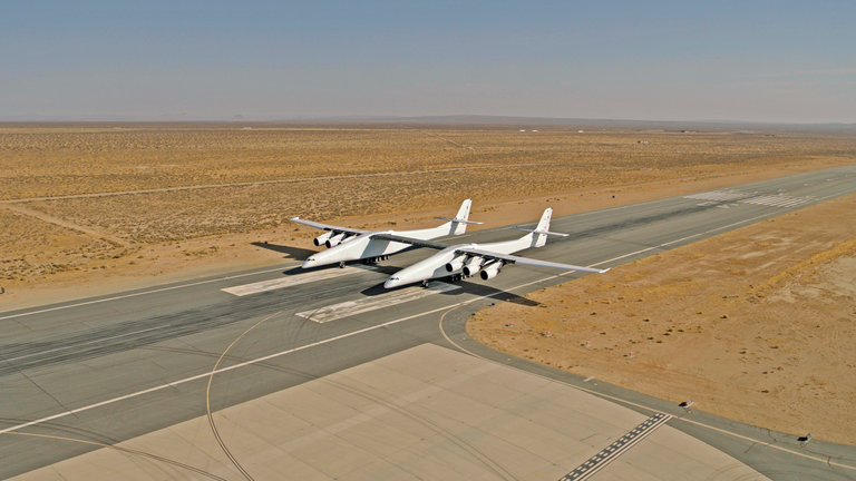
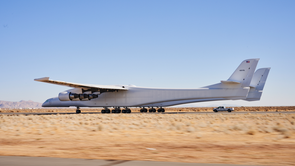
Stratolaunch first flight
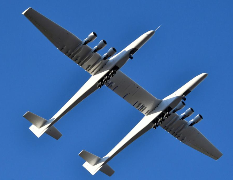
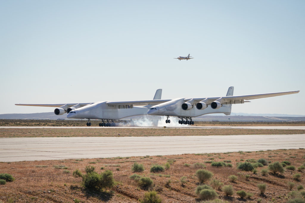
The Stratolaunch aircraft, named Roc, made an unannounced first flight from the Mojave Air & Space Port on 13 April 2019. The aircraft stayed aloft for 2.5 hours, reached a peak altitude of 17,000 feet (5,180 m) and a top speed of 189 mph (304 kph). The following series of photos show the Stratolaunch aircraft during its first flight.
Source, above two photos: Stratolaunch SystemsSource: REUTERS/Gene Blevins/File PhotoLanding at the conclusion of the first flight. Source: Stratolaunch Systems
Stratolaunch posted an impressive short video of the first flight, which you can view here:
Stratolaunch family of launch vehicles: ambitious plans, but subject to change
In August 2018, Stratolaunch announced its ambitious launch vehicle development plans, which included the family of launch vehicles shown in the following graphic:
Up to three Pegasus XL launch vehicles from Northrop Grumman Innovation Systems (formerly Orbital ATK) can be carried on a single Stratolaunch flight. Each Pegasus XL is capable of placing up to 370 kg (816 lb) into a low Earth orbit (LEO, 400 km / 249 mile circular orbit).
Medium Launch Vehicle (MLV) capable of placing up to 3,400 kg (7,496 lb) into LEO and intended for short satellite integration timelines, affordable launch and flexible launch profiles. MLV was under development and first flight was planned for 2022.
Medium Launch Vehicle – Heavy, which uses three MLV cores in its first stage. That vehicle would be able to place 6,000 kg (13,228 lb) into LEO. MLV-Heavy was in the early development stage.
A fully reusable space plane named Black Ice, initially intended for orbital cargo delivery and return, with a possible follow-on variant for transporting astronauts to and from orbit. The space plane was a design study.
Stratolaunch was developing a 200,000 pound thrust, high-performance, liquid fuel hydrogen-oxygen rocket engine, known as the “PGA engine”, for use in their family of launch vehicles. Additive manufacturing was being widely used to enable rapid prototyping, development and manufacturing. Successful tests of a 100% additive manufactured major subsystem called the hydrogen preburner were conducted in November 2018.
Stratolaunch Systems planned family of launch vehicles announced in August 2018. Source: Stratolaunch Systems
After Paul Allen’s death on 15 October 2018, the focus of Stratolaunch Corp was greatly revised. On 18 January 2019, the company announced that it was ending work on its own family of launch vehicles and the PGA rocket engine. The firm announced, “We are streamlining operations, focusing on the aircraft and our ability to support a demonstration launch of the Northrop Grumman Pegasus XL air-launch vehicle.”
You’ll find an article describing Stratolaunch Systems’ frequently changing launch vehicle plans in an article on the SpaceNews website here:
Air launch offers a great deal of flexibility for launching a range of small-to-medium sized satellites and other aerospace vehicles. With only the Pegasus XL as a launch vehicle, and with Northrop Grumman having their own Stargazer carrier aircraft for launching the Pegasus XL, the business case for the Stratolaunch aircraft has been greatly weakened.
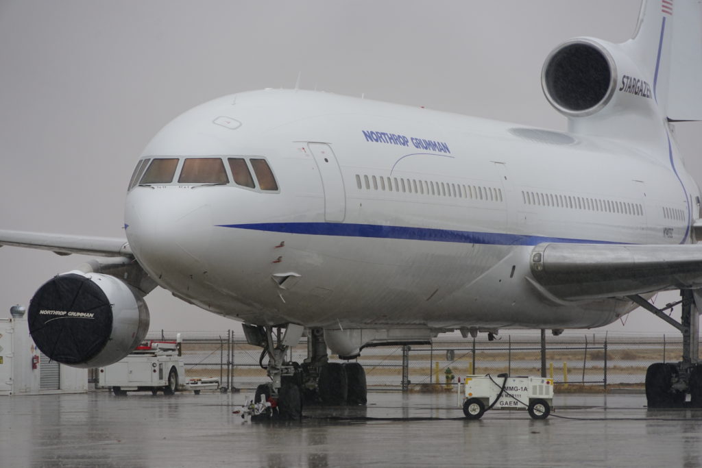
Stratolaunch’s main competition: The Northrop Grumman Stargazer at the Mojave Air and Space Port in January 2019, available for its next Pegasus XL launch mission. Source: Author’s photo
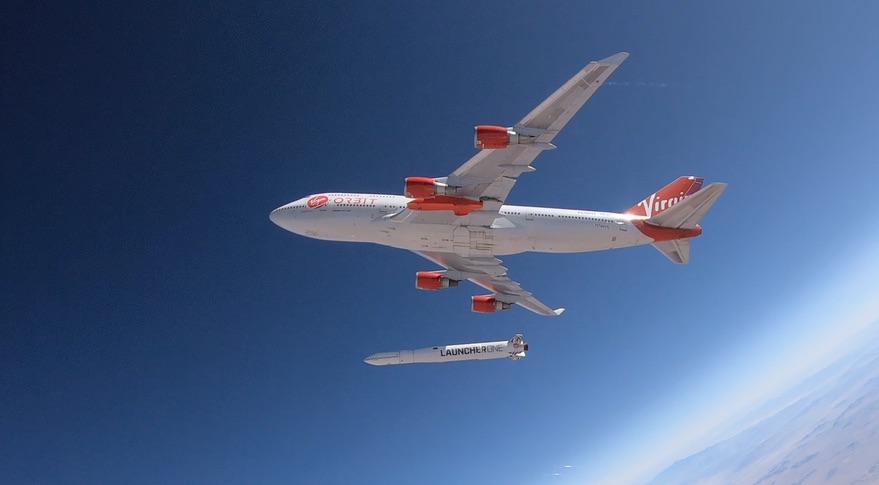
Additional competition in the airborne launch services business will come in 2020 from Richard Branson’s firm Virgin Orbit, with its airborne launch platform Cosmic Girl, a highly-modified Boeing 747, and its own launch vehicle, known as LauncherOne. Successful drop tests of LauncherOne were conducted in 2019. The first launch to orbit is expected to occur in 2020. You’ll find more information on the Virgin Orbit website here: https://virginorbit.com
An inert LauncherOne rocket falls away from its 747 carrier aircraft in a July 2019 drop test. Source: Virgin Orbit
Additional competition for small satellite launch services comes from the newest generation of small orbital launch vehicles, like Electron (Rocket Lab, New Zealand) and Prime (Orbix, UK), which are expected to offer low price launch services from fixed land-based launch sites. Electron is operational now, and achieved six successful launches in six attempts in 2019. Prime is expected to enter service in 2021.
In the cost competitive launch services market, Stratolaunch does not seem to have an advantage with only the Pegasus XL in its launch vehicle inventory. Hopefully, they have something else up their sleeve that will take advantage of the remarkable capabilities of the Stratolaunch carrier aircraft.
19 March 2020 Update: Stratolaunch change of ownership
Several sources reported on 11 October 2019 that Stratolaunch Systems had been sold by its original holding company, Vulcan Inc., to an undisclosed new owner. Two months later, Mark Harris, writing for GeekWire, broke the news that the private equity firm Cerberus Capital Management was the new owner. It appears that Jean Floyd, Stratolaunch’s president and CEO since 2015, remains in his roles for now. Michael Palmer, Cerberus’ managing director, was named Stratolaunch’s executive vice president. You can read Mark Harris’ report here: https://www.geekwire.com/2019/exclusive-buyer-paul-allens-stratolaunch-space-venture-secretive-trump-ally/
It will be interesting to watch as the new owners reinvent Stratolaunch Systems for the increasingly competitive market for airborne launch services.
In my 6 August 2016 post, “Lunar Lander XCHALLENGE and Lunar XPrize are Paving the way for Commercial Lunar Missions,” I reported on the status of the Google Lunar XPrize, which was created in 2007 to “incentivize space entrepreneurs to create a new era of affordable access to the Moon and beyond,” and actually deliver payloads to the Moon. In addition, the lunar payloads were tasked with moving 500 meters (1,640 feet) after landing and transmitting high-definition photos and video back to Earth. Any additional science data would be a plus. In January 2018, after concluding that none of the remaining competitors could meet the extended 31 March 2018 deadline for landing on the Moon, the Google Lunar XPrize competition was cancelled, with the $30M in prizes remaining unclaimed. You can read this post here:
One of the competing Lunar XPrize teams was SpaceIL from Israel, which was developing a small lunar spacecraft named Beresheet (originally named Sparrow), that was designed to hitch a ride into an elliptical Earth orbit as a secondary payload on a SpaceX Falcon 9 commercial launch vehicle and then transfer itself to a lunar orbit and finally land on the Moon.
The SpaceIL lunar landing program continued after cancellation of the Lunar XPrize competition. You’ll find details on the SpaceIL lunar program here:
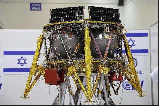
As completed by SpaceIL and Israel Aerospace Industries (IAI), the Beresheet spacecraft has a launch mass of 600 kg (1,323 pounds) and a landing mass of about 180 kg (397 pounds). The lander carries imagers, a magnetometer, a laser retro-reflector array (LRA) provided by the U.S. National Aeronautics and Space Administration (NASA), and a time capsule of cultural and historical Israeli artifacts.
The Beresheet spacecraft. Source: by Abir Sultan/EPA-EFE
After landing on the Moon, the Beresheet spacecraft electronic systems are expected to remain operational only for a few days. The original Lunar XPrize plan to demonstrate mobility and move the spacecraft after landing on the Moon has been dropped. The laser retro-reflectors will enable the spacecraft to serve as a fixed geographic reference point on the lunar surface long after the mission ends.While not designed for a long lunar surface mission, Beresheet is intended to demonstrate advances in technology that enable low-cost, privately-funded missions to another body in the solar system. Beresheet was developed and constructed for about $100 million. You’ll find more information on the Beresheet spacecraft here:
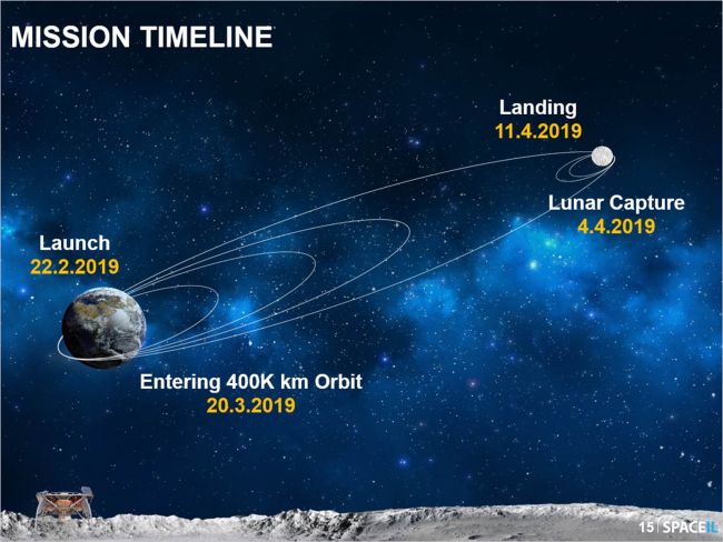
Beresheet was launched from Cape Canaveral, FL on 21 Feb 2019 into an initial elliptical Geosynchronous Transfer Orbit (GTO) that was dictated by the requirements for the Falcon 9 booster’s primary payload. Once in GTO, Beresheet used its small rocket engine to gradually raise its orbit to a 400,000 km (248,548 mile) apogee to intersect the Moon’s circular orbit, and phase its orbit so the spacecraft passed close to the Moon and could maneuver into a transfer orbit and be captured by the Moon’s gravity. This mission profile is illustrated below.
Source: SpaceIL
You can watch a short video with an animation of this mission profile here:
On 4 April, SpaceIL tweeted: “Critical lunar orbit capture took place successfully. #Beresheet is now entering an elliptical course around the #moon, as we get closer to the historical landing #11.4″
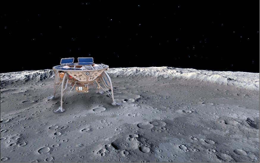
After circularizing its lunar orbit, Beresheet is scheduled to land on the Moon on 11 April 2019. NASA is providing communications support during the mission.
Artist’s concept of the Beresheet lander on the lunar surface. Source: Israel Aerospace Industries(IAI)
On 28 March, the X Prize founder and Executive Chairman Peter Diamand announced that, if the lunar landing is successful, the Foundation would award a $1 million “Moonshot Award” to Beresheet’s builders. Peter Diamand noted, “SpaceIL’s mission represents the democratization of space exploration.”
Best wishes to the SpaceIL team for a successful lunar landing. If successful, Israel will become the 4thnation, after Russia (Soviet Union), USA and China to land spacecraft on the Moon.
Update 12 April 2019: Beresheet spacecraft crashed during Moon landing attempt
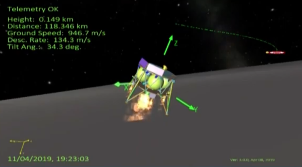
The Beresheet spacecraft successfully initiated its descent from lunar orbit on 11 April 2019. Initial telemetry indicated that the landing profile was proceeding as planned.
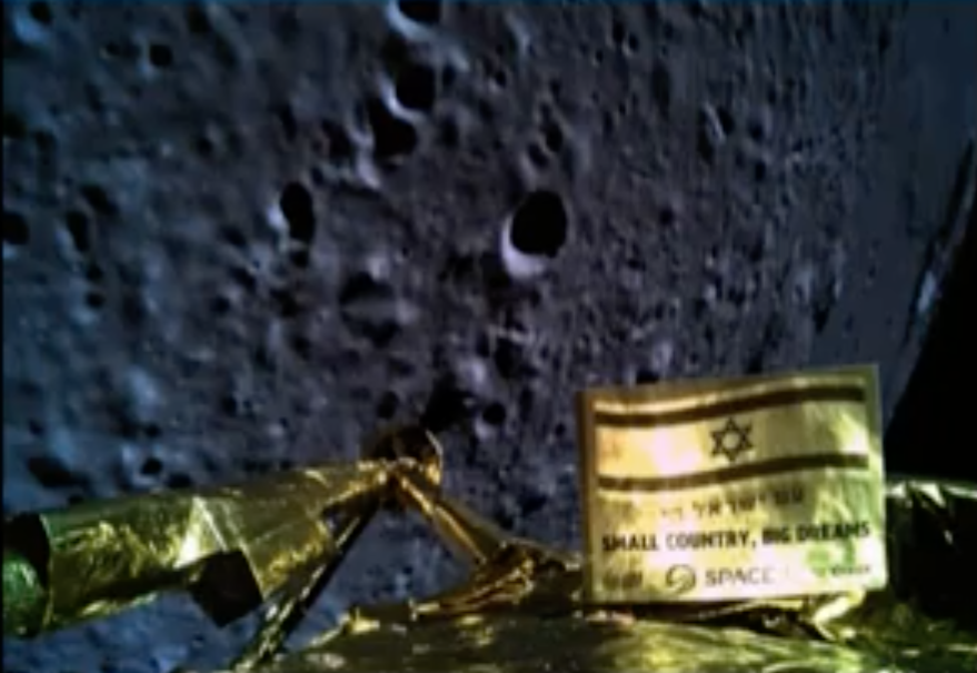
Beresheet status graphic during landing sequence. Source: IAI / SpaceILPhoto taken from Beresheet during the descent, from an altitude of about 22 km. Source: IAI / SpaceIL
Communications with the spacecraft was lost when Beresheet was about 489 feet (149 meters) above the moon’s surface. Opher Doron, the general manager of IAI, reported during the live broadcast, “We had a failure in the spacecraft; we unfortunately have not managed to land successfully.”
X Prize founder and Executive Chairman Peter Diamandis announced that SpaceIL and IAI will receive the $1 million Moonshot Award despite failing to make the planned soft landing on the Moon.
Update 14 May 2019: Preliminary failure analysis
On 17 April 2019, SpaceIL announced that its preliminary failure analysis indicated that a software command uploaded to restart a failed inertial measuring unit (IMU) may have started a sequence of events that ultimately shut down the main engines prematurely during the landing attempt, resulting in the crash of the Beresheet spacecraft.
Morris Kahn, SpaceIL’s primary source of funding, pledged that the team will try again for a Moon landing with a new spacecraft dubbed “Beresheet 2.0,” which will incorporate lessons learned from the first lunar landing attempt.
For more information on the Beresheet mission, see The Planetary Society mission report at the following link:
Peter Lobner, updated 24 Jan 2019, 12 Nov 2019 and 17 October 2023
The National Aeronautics and Space Administration’s (NASA) durable New Horizon spacecraft made its close flyby of Pluto on 14 July 2015, passing 7,800 mi (12,500 km) above the surface of that dwarf planet and returning a remarkable trove of photos and data. Since then, the spacecraft has been continuing its journey out of our solar system and now is flying through the Kuiper Belt, which is a very large, diffuse region beyond the orbit of Neptune containing millions of small bodies in distant orbits around the Sun. These Kuiper Belt Objects (KBOs) are believed to be “leftovers” (i.e., they never coalesced into planets) from the formation of the early solar system. You can read more about the Kuiper Belt on the NASA website here:
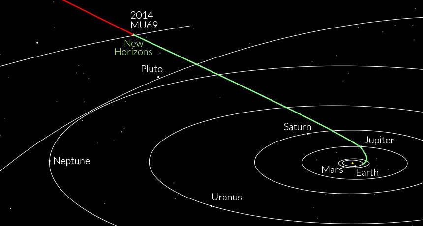
On 28 August 2015, NASA announced that it had selected the next destination for New Horizons after the Pluto flyby: a small KBO designated 2014 MU69, originally named Ultima Thule, about 1 billion miles (1.6 billion km) beyond Pluto. The spacecraft’s trajectory from Earth to Ultima Thule is shown in the following NASA diagram.
Source: NASA, Johns Hopkins University Applied Physics Lab, Southwest Research Institute
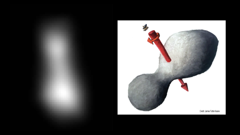
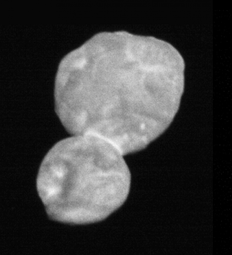
On 1 January 2019, the New Horizons spacecraft made a close flyby of 2014 MU69, at a range of 2,200 miles (3,500 km) and a relative speed of 14 kilometers per second (31,317 mph). At a distance of 4.1 billion miles (6.6 billion km) from the Earth, radio signals took 6 hours and 6 minutes traveling at the speed of light to traverse the distance between the spacecraft and Earth during the encounter. On 1 January 2019, NASA released the following blurry image, which was taken at long range.
Credits: NASA/JHUAPL/SwRI; sketch courtesy of James Tuttle Keane
NASA reported: “At left is a composite of two images taken by New Horizons’ high-resolution Long-Range Reconnaissance Imager (LORRI), which provides the best indication of Ultima Thule’s size and shape so far. Preliminary measurements of this Kuiper Belt object suggest it is approximately 20 miles long by 10 miles wide (32 kilometers by 16 kilometers). An artist’s impression at right illustrates one possible appearance of Ultima Thule, based on the actual image at left. The direction of Ultima’s spin axis is indicated by the arrows. “
In the weeks following the flyby, New Horizons will be downloading all of the higher-resolution photos and data acquired during its close encounter with 2014 MU69 and we’ll be getting a much more detailed understanding of this KBO.
It appears that NASA has the opportunity to target one or more additional KBOs for future New Horizons flybys in the 2020s. The spacecraft’s electric power source, a plutonium (Pu-238)-fueled radioisotope thermoelectric generator (RTG), is capable of providing power well into the 2030s, albeit at gradually reducing power levels. In addition, the spacecraft has significant hydrazine fuel remaining for course correction and attitude control en route to a future KBO flyby.
On 2 January 2019, NASA released the following photo taken on the inbound leg of the flyby, still 18,000 miles (28,000 km) from 2014 MU69.
Source: NASA/Johns Hopkins University Applied Physics Laboratory/Southwest Research Institute
You’ll find more information on NASA’s New Horizons mission here:
24 January 2019 update: Latest photo shows 2014 MU69 surface to be unusually smooth
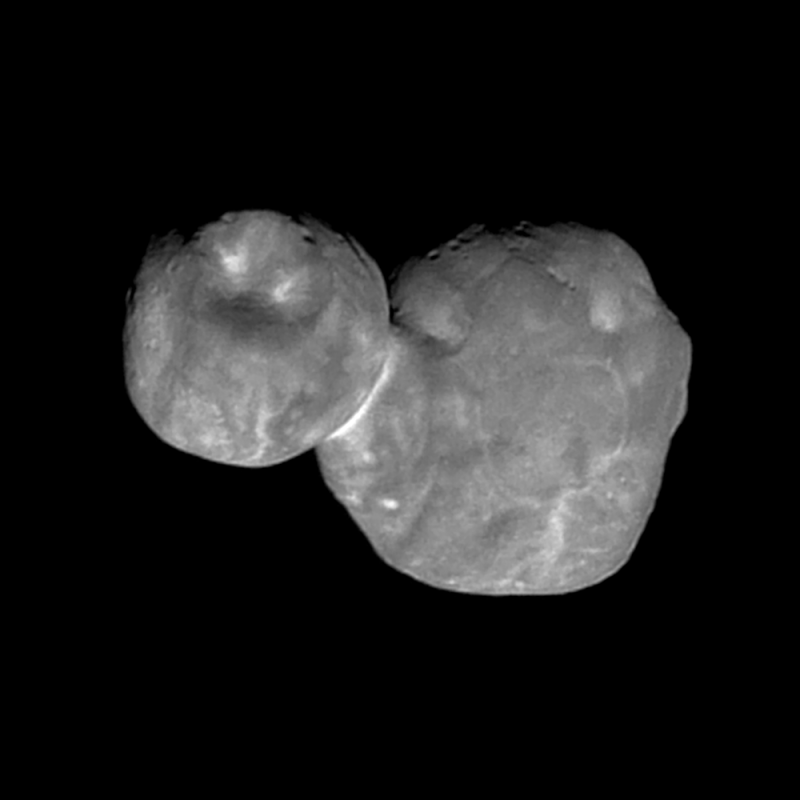
Today, NASA released the following photo of 2014 MU69, taken at a distance of 4,200 miles (6,700 kilometers) on 1 January 2019, just seven minutes before closest approach. Principal Investigator Alan Stern, of the Southwest Research Institute, reported, “Over the next month there will be better color and better resolution images that we hope will help unravel the many mysteries of Ultima Thule.”
Source: NASA/Johns Hopkins University Applied Physics Laboratory/Southwest Research Institute
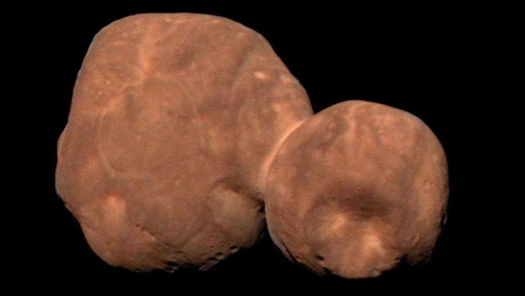
12 November 2019 update: 2014 MU69 renamed
NASA announced that 2014 MU69 was formally renamed “Arrokoth”, which NASA says “means ‘sky’ in the language of the Powhatan people, a Native American tribe indigenous to Maryland. The state is home to New Horizons mission control at the Johns Hopkins University Applied Physics Laboratory in Laurel.” Here’s a colorized view of Arrokoth.
Source: NASA/Johns Hopkins University Applied Physics Laboratory/Southwest Research Institute
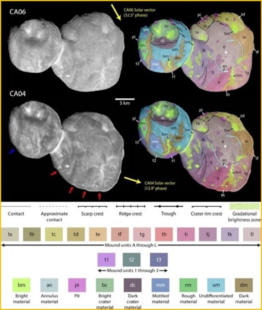
17 October 2023 update: Analysis of Arrokoth’s structure
In September 2023, a research team from the Southwest Research Institute (SwRI) in Boulder, Colorado reported the results of their detailed analysis of Arrokoth, focusing on 12 mounds identified on the larger lobe, named Wenu, and tentatively, three on the smaller lobe, named Weeyo.
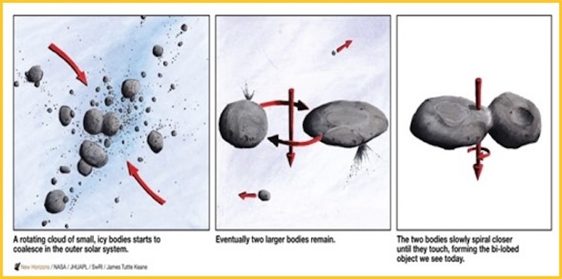
As reported by EarthSky, “The data from New Horizons suggest that the mounds have a common origin. In this case, that common origin would date back to when Arrokoth first formed billions of years ago. As with planets and moons, the Kuiper Belt object formed when various chunks and bits of material collided together, creating the larger planetesimal now known as Arrokoth.” This formation process is shown in the following diagram.
Data from New Horizons suggests that Arrokoth formed from material that collided together at slow speeds. Source: New Horizons/ NASA/ JHUAPL/ SwRI/ James Tuttle Keane.
The locations and structure of the mounds on Arrokoth are shown in the following graphic.
The mound structures dominate Arrokoth’s larger lobe (named Wenu). In addition, there are a few tentative mounds identified on the smaller lobe (named Weeyo). Source: SwRI via EarthSky
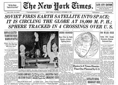
4 October 1957 was a major milestone in aerospace history, marking the first launch of an artificial satellite into Earth orbit. Since 1955, a relatively low-key “space race” between the U.S. and the Soviet Union had been underway, with the U.S. openly developing the small Vanguard booster rocket and satellite and planning to launch the first satellite into orbit during the International Geophysical Year (1 July 1957 to 31 December 1958). Secrecy surrounding the Soviet Union’s space program made the successful launch of Sputnik 1 a significant political coup. This event served to greatly energized the lagging U.S. space program and prompted calls for more technical education in the U.S.
Source: The New York Tines
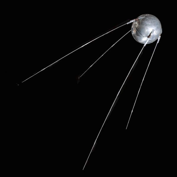
The small spherical Sputnik 1 satellite had a diameter of 23 inches (58 cm) and a weight of 184 pounds (83.6 kg). Functionally, Sputnik 1 was very simple, consisting of a battery power supply, a radio transmitter, a thermal control system and a remote control switch housed within the nitrogen-pressurized sphere. You’ll find a description of how Sputnik 1 worked at the following link:
The satellite transmitted a continuous “beep-beep-beep…” on two frequencies until 28 October 1957, when it went silent.
The four whip antennae provided a spherical radiation pattern for the broadcast radio signals. Source: Smithsonian Air and Space Museum
Sputnik 1 interior arrangement. The silver-zinc batteries were in the hexagonal enclosure. The radio transmitters were in the center of that hexagon. Source: Space.com
Sputnik 1’s low Earth orbit decayed over the next three months and the satellite reentered the Earth’s atmosphere and was destroyed on 4 January 1958, after about 1,400 orbits.
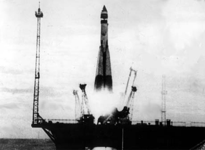
Sputnik 1 was launched by an R-7 liquid-fueled booster rocket, which was a version of the Soviet Union’s first intercontinental ballistic missile (ICBM), the SS-6. The R-7 booster rocket, which consisted of a liquid-fueled core stage surrounded by four liquid-fueled strap-on boosters, was developed by the design bureau headed by Sergei Pavlovitch Korolev (1906-1966). The strap-on boosters separated about 116 seconds after launch. The core stage achieved orbit along with the Sputnik 1 satellite and the payload fairing. The core stage reentered the atmosphere in December 1957.
R-7 booster. Source: Space.com
The R-7 booster evolved into the launch vehicle for future Soviet Vostok, Voskhod and Soyuz missions, and a version continues in use today as the Russian launch vehicle taking astronauts and supplies to the International Space Station (ISS) aboard updated Soyuz spacecraft.
Evolution of the R-7 booster. Source: NASA / Peter Gorin / Emmanuel Dissais
The R-7 booster launched the larger Sputnik 2 satellite into earth orbit on 3 November 1957, before any satellite launch attempt by the U.S. Sputnik 2 carried the first living thing into orbit, the “space dog” named Laika. The even larger Sputnik 3 was launched on 15 May 1958. These first three Sputnik launches had lasting effects on the civilian space race and the military missile race between the U.S. and the Soviet Union.
The U.S. civilian Earth Satellite Program (aka Project Vanguard) favored by President Dwight Eisenhower, planned to launch the first U.S. earth-orbiting satellite during the International Geophysical Year (IGY, 1 July 1957 – 31 December 1958) using a Vanguard rocket being developed by Naval Research Laboratory (NRL). Vanguard was quickly eclipsed by the Army Ballistic Missile Agency’s satellite program, which was hastily mobilized after the Sputnik 1 launch. The Army – Jet Propulsion Laboratory (JPL) team, led by Dr. Werner von Braun (Army) and Dr. William Pickering (JPL), was successful on their first attempt and placed the first U.S. satellite, Explorer I, in orbit on 31 January 1958. After two launch failures, the first Vanguard satellite reached orbit on 17 March 1958.
Thereafter, the Soviet – U.S. space race was a focus of national and international attention, with President John F. Kennedy setting a seemingly optimistic national goal in 1961: “…before this decade is out, of landing a man on the Moon and returning him safely to the Earth….” The U.S. Apollo 11 mission met this goal when the astronauts Neil Armstrong and Edwin “Buzz” Aldrin, Jr. landed on the Moon on 20 July 1969, just 12 years after Sputnik 1 first reached earth orbit.
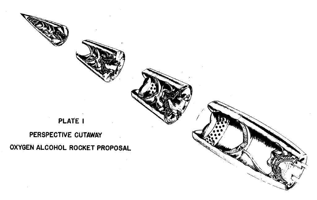
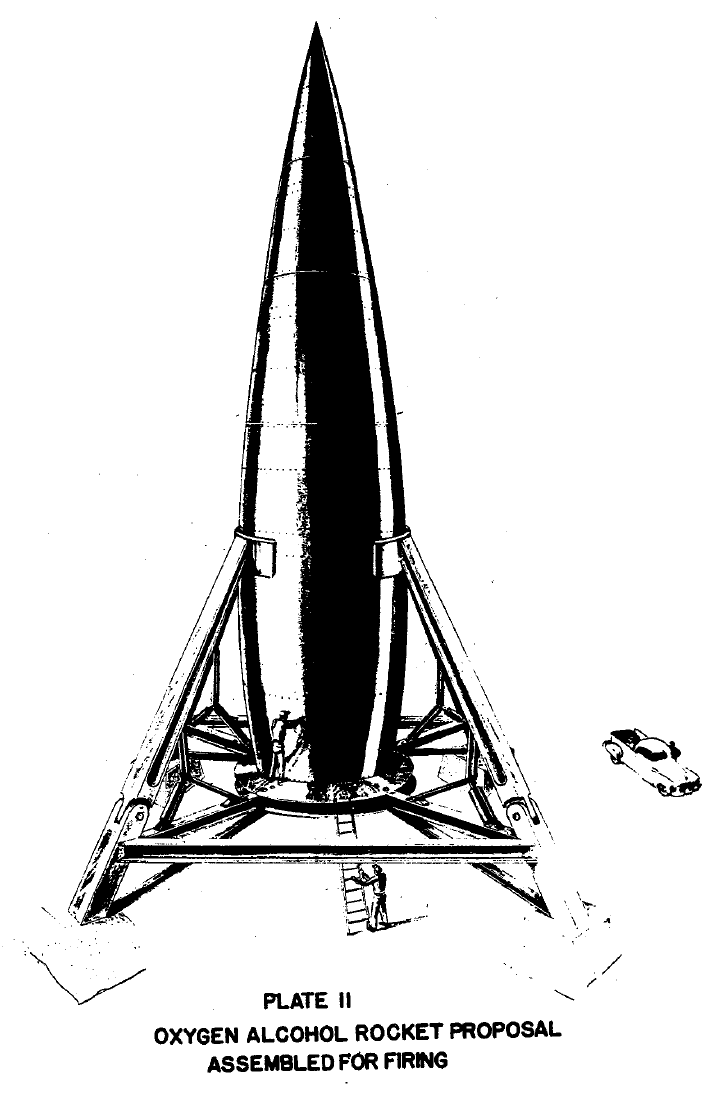
The title of this post also is the title of the first RAND report, SM-11827, which was issued on 5 May 1946 when Project RAND still was part of the Douglas Aircraft Company. The basic concept for an oxygen-alcohol fueled multi-stage world-circling spaceship is shown below.
Source: RAND
Source: RAND
Now, more than 70 years later, it’s very interesting to read this report to gain an appreciation of the state of the art of rocketry in the U.S. in 1946, which already was benefiting from German experience with the V-2 and other rocket programs during WW II.
RAND offers the following abstract for SM-11827:
“More than eleven years before the orbiting of Sputnik, history’s first artificial space satellite, Project RAND — then active within Douglas Aircraft Company’s Engineering Division — released its first report: Preliminary Design of an Experimental World-Circling Spaceship (SM-11827), May 2, 1946. Interest in the feasibility of space satellites had surfaced somewhat earlier in a Navy proposal for an interservice space program (March 1946). Major General Curtis E. LeMay, then Deputy Chief of the Air Staff for Research and Development, considered space operations to be an extension of air operations. He tasked Project RAND to undertake a feasibility study of its own with a three-week deadline. The resulting report arrived two days before a critical review of the subject with the Navy. The central argument turns on the feasibility of such a space vehicle from an engineering standpoint, but alongside the curves and tabulations are visionary statements, such as that by Louis Ridenour on the significance of satellites to man’s store of knowledge, and that of Francis Clauser on the possibility of man in space. But the most riveting observation, one that deserves an honored place in the Central Premonitions Registry, was made by one of the contributors, Jimmy Lipp (head of Project RAND’s Missile Division), in a follow-on paper nine months later: ‘Since mastery of the elements is a reliable index of material progress, the nation which first makes significant achievements in space travel will be acknowledged as the world leader in both military and scientific techniques. To visualize the impact on the world, one can imagine the consternation and admiration that would be felt here if the United States were to discover suddenly that some other nation had already put up a successful satellite.’”
You can buy the book from several on-line sellers or directly from RAND. However you also can download the complete report for free in three pdf files that you’ll find on the RAND website at the following link:
On 12 April 1961, the Soviet Union launched the Vostok 1 (“East” 1) spacecraft and astronaut Major Yuri Gagarin from a launch site in Kazakhstan on the first ever manned space mission. Gagarin became the first person to fly above the Karman line that marks the beginning of space, at 62 miles (330,000 feet, 100 km) above the Earth. He also became the first person to achieve Earth orbit.
Yuri Gagarin. Source: Daily Mail
Basic orbital parameters for Vostok 1 were: apogee: 203 miles (327 km), perigee: 117 miles (189 km), and orbital period: 89.1 minutes. Gagarin completed one orbit. After re-entry, Gagarin ejected from the Vostok capsule at an altitude of about 4.3 miles (7 km) and parachuted to the ground. The capsule descended under its own parachute and was recovered near Engels, Russia. Gagarin’s total flight time was 1 hour, 48 minutes.
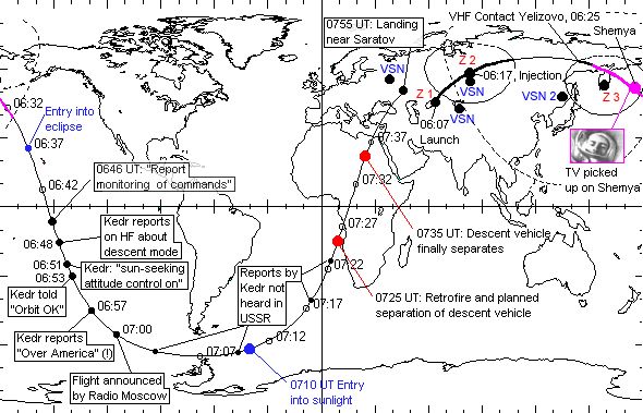
The path of Gagarin’s historic flight, including important flight milestones, is shown on the following map:
Source: http://space.stackexchange.com/
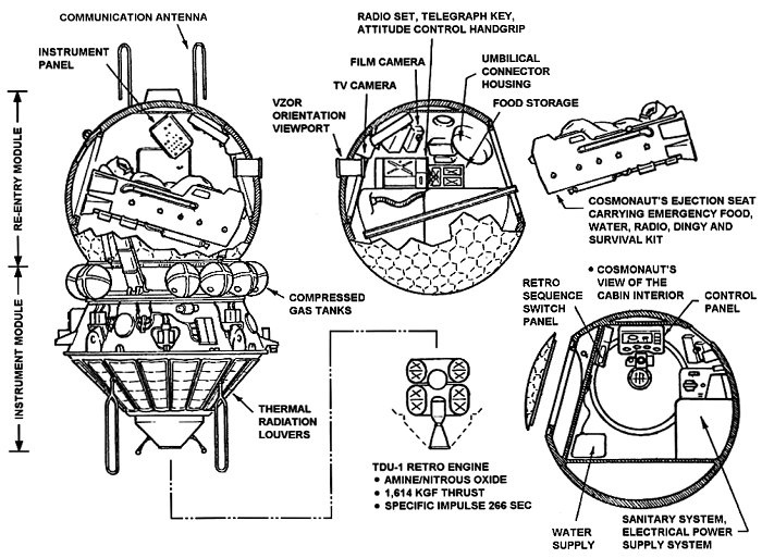
The configuration of the Vostok spacecraft is shown in the following diagram. The reentry vehicle is the spherical capsule, which on the left is shown attached to the instrument module.
Vostok 1 configuration. Source: Pinterest
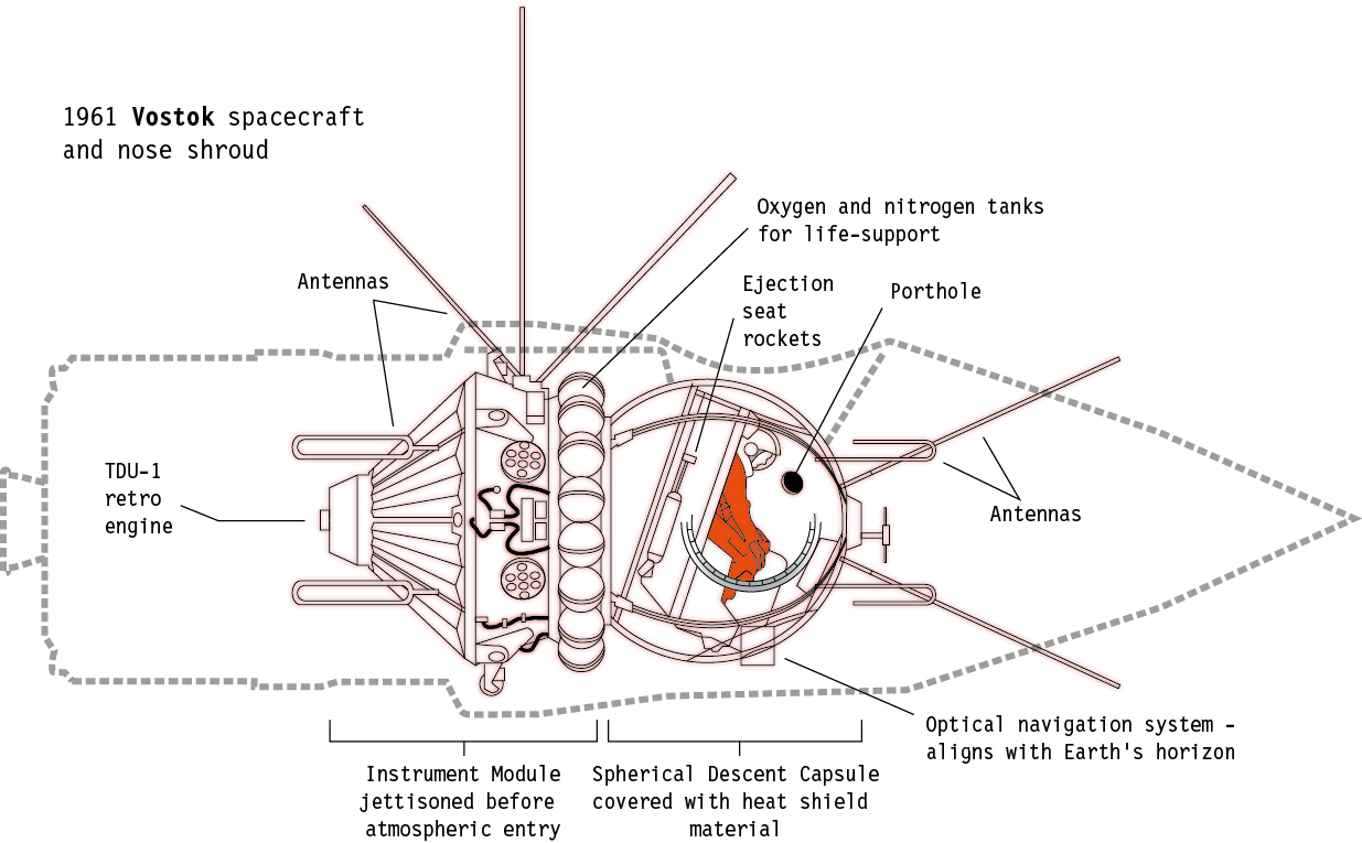
The complete spacecraft had a mass of 4.73 tons (4,300 kg) and measured 14.4 feet (4.4 meters) in length and 8 feet (2.43 meters) in diameter. The placement of the spacecraft inside the nose shroud of the launch vehicle is shown in the following diagram.
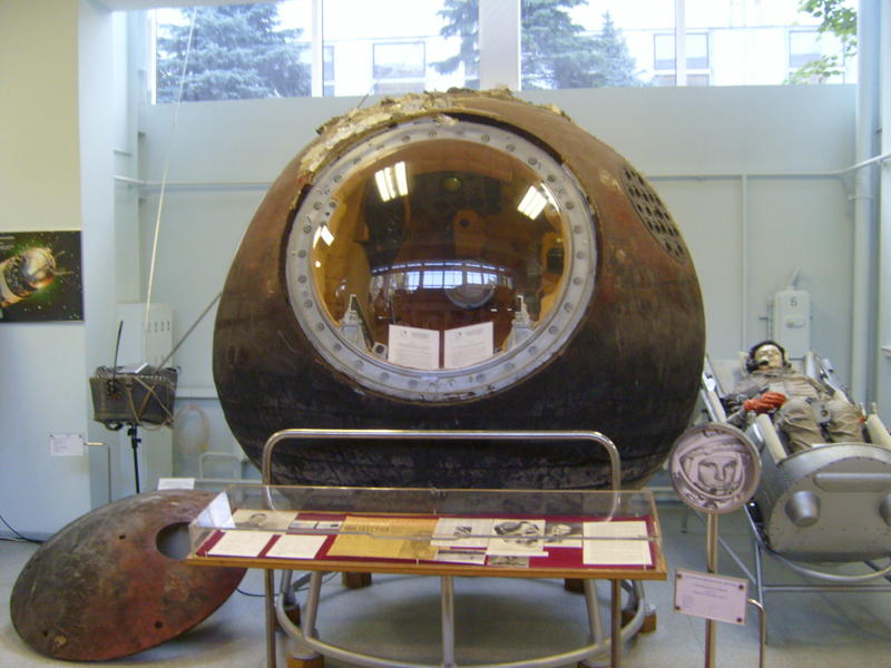
Yuri Gagarin’s Vostok I capsule is on display at the RKK Energiya museum, which is on the grounds of the RKK Energiya factory in Korolyov, near Moscow. Gagarin died in a jet training flight on 27 March 1968.
Vostok 1 capsule. Source: SiefkinDR – Own work, CC BY-SA 3.0, https://commons.wikimedia.org/w/index.php?curid=12403404
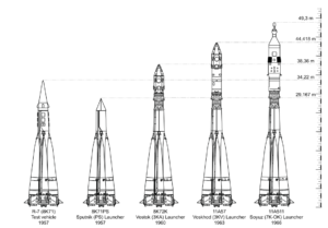
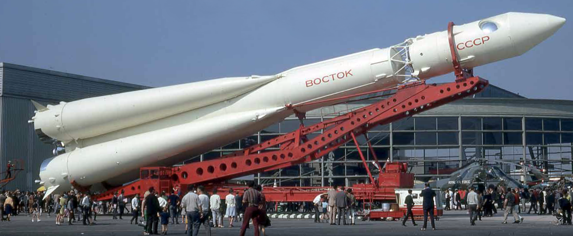
The Soviet’s Vostok launch vehicle was unveiled to the public at the June 1967 Paris Air Show. This was a big launch vehicle for the time, with a length of 126 feet (38.4 m) and a diameter of about 35 feet (10.7 m).
Soviet Vostok launcher mockup at 1976 Paris Air Show. Source: http://www.theaviationhistorian.com
The Vostok launcher, designed by Sergei Korolov, was based on the Soviet R-7 (Semyorka) intercontinental ballistic missile (ICBM). Earlier versions of the R-7 were used to put the first man-made satellite, Sputnik 1, in Earth orbit on 4 October 1957 and to launch the early Luna spacecraft that, in 1959, achieved the milestones of first spacecraft to escape Earth’s gravity and enter a solar orbit (Luna 1) and first spacecraft to impact the Moon (Luna 2).
About one month after Gagarin’s milestone orbital flight, U.S. Project Mercury astronaut Alan Shepard was launched on 5 May 1961 by a Mercury-Redstone booster on a 15-minute suborbital flight. In the Freedom 7 capsule, Shepard reached a maximum altitude of 116.5 miles (187.5 km) and was recovered about 302 miles (487 km) downrange from Cape Canaveral after landing in the Atlantic Ocean. The Freedom 7 capsule is on display in the museum at the John F. Kennedy Presidential Library on Columbia Point in Boston, on loan from the Smithsonian National Air and Space Museum. Alan Shepard died on 21 July 1998.
On 20 February 1962, astronaut John Glenn became the first American to reach Earth orbit. The Mercury-Atlas booster placed the Friendship 7 capsule and Glenn into a low Earth orbit with the following basic parameters: apogee: 154 miles (248 km), perigee: 87 miles (140 km), and orbital period: 88.5 minutes. Glenn completed three orbits in a flight lasting 4 hours and 55 minutes, with recovery in the Atlantic Ocean. The Friendship 7 capsule is on display at the Smithsonian National Air and Space Museum, Washington D.C. John Glenn died on 8 December 2016.
A comparison of the Mercury and Vostok reentry capsules is shown in the following scale diagram.
So here we are, 56 years later and some things haven’t changed. Just as in 1961, the U.S. has no means of its own to send astronauts into Earth orbit. The first orbital test of an unmanned SpaceX Dragon 2 spacecraft, launched by a SpaceX Falcon booster, is scheduled for November 2017, with the first crewed mission occurring in 2018. When it occurs, this manned Dragon 2 mission will be the first U.S. manned spacecraft to reach orbit since the last Space Shuttle flight in 2011. Dragon 2 will provide regular service to replace International Space Station (ISS) crews and to perform other orbital missions requiring a crew. In the meantime, the U.S. depends on Russia and their Soyuz spacecraft to deliver and return crews from the ISS. Soyuz is a larger, more modern version of the basic Vostok spacecraft and spherical reentry capsule. You can find out more about the Soyuz spacecraft currently serving the ISS on the National Aeronautics and Space Administration (NASA) website at the following link:
NASA’s manned space program will take even longer to resume manned spaceflight missions. The first launch of NASA’s Space Launch System (SLS) with the new Orion multi-purpose crew vehicle currently is expected to occur in 2018. As currently planned, the Exploration Mission 1 (EM-1) will be an unmanned mission. NASA is considering making EM-1 a manned mission and launching in 2019.


