Category Archives: All Posts

Antarctica – What’s Under All That Ice?

Peter Lobner, Updated 24 August 2021

From space, Antarctica gives the appearance of a large, ice-covered continental land mass surrounded by the Southern Ocean.  The satellite photo mosaic, below, reinforces that illusion.  Very little ice-free rock is visible, and it’s hard to distinguish between the continental ice sheet and ice shelves that extend into the sea.

Satellite mosaic image of Antarctica created by Dave Pape, 
adapted to the same orientation as the following maps. 
 Source.  https://geology.com/world/antarctica-satellite-image.shtml

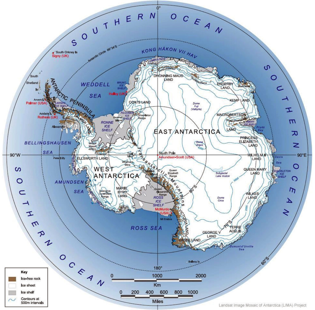
The following topographical map presents the surface of Antarctica in more detail, and shows the many ice shelves (in grey) that extend beyond the actual coastline and into the sea.  The surface contour lines on the map are at 500 meter (1,640 ft) intervals.

Map of Antarctica and the Southern Ocean showing the topography of Antarctica (as blue lines), research stations of the United States and the United Kingdom (in red text), ice-free rock areas (in brown), ice shelves (in gray) and names of the major ocean water bodies (in blue uppercase text).
Source: LIMA Project (Landsat Image Mosaic of Antarctica) via Wikipedia

The highest elevation of the ice sheet is 4,093 m (13,428 ft) at Dome Argus (aka Dome A), which is located in the East Antarctic Ice Sheet, about 1,200 kilometers (746 miles) inland.  The highest land elevation in Antarctica is Mount Vinson, which reaches 4,892 meters (16,050 ft) on the north part of a larger mountain range known as Vinson Massif, near the base of the Antarctic Peninsula.  This topographical map does not provide information on the continental bed that underlies the massive ice sheets.

A look at the bedrock under the ice sheets: Bedmap2 and BedMachine

In 2001, the British Antarctic Survey (BAS) released a topographical map of the bedrock that underlies the Antarctic ice sheets and the coastal seabed derived from data collected by international consortia of scientists since the 1950s. The resulting dataset was called  BEDMAP1.  

In a 2013 paper, P. Fretwell, et al. (a very big team of co-authors), published the paper, “Bedmap2: Improved ice bed, surface and thickness datasets for Antarctica,” which included the following bed elevation map, with bed elevations color coded as indicated in the scale on the left.  As you can see, large portions of the Antarctic “continental” bedrock are below sea level.

Bedmap2 bed elevation grid.  Source:  Fretwell 2013, Fig. 9

You can read the 2013 Fretwell paper here:  https://www.the-cryosphere.net/7/375/2013/tc-7-375-2013.pdf

For an introduction to Antarctic ice sheet thickness, ice flows, and the topography of the underlying bedrock, please watch the following short (1:51) 2013 video, “Antarctic Bedrock,” by the National Aeronautics and Space Administration’s (NASA’s) Scientific Visualization Studio:

NASA explained:

  • “In 2013, BAS released an update of the topographic dataset called BEDMAP2 that incorporates twenty-five million measurements taken over the past two decades from the ground, air and space.”
  • “The topography of the bedrock under the Antarctic Ice Sheet is critical to understanding the dynamic motion of the ice sheet, its thickness and its influence on the surrounding ocean and global climate. This visualization compares the new BEDMAP2 dataset, released in 2013, to the original BEDMAP1 dataset, released in 2001, showing the improvements in resolution and coverage.  This visualization highlights the contribution that NASA’s mission Operation IceBridge made to this important dataset.”

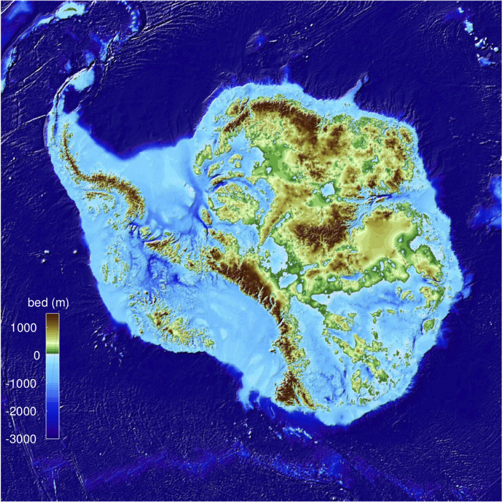
On 12 December 2019, a University of California Irvine (UCI)-led team of glaciologists unveiled the most accurate portrait yet of the contours of the land beneath Antarctica’s ice sheet.  The new topographic map, named “BedMachine Antarctica,”  is shown below.

BedMachine Antarctica topographical map showing the underlying ground features and the large portions of the continental bed that are below sea level.  
 Credit: Mathieu Morlighem / UCI

UCI reported:

  • “The new Antarctic bed topography product was constructed using ice thickness data from 19 different research institutes dating back to 1967, encompassing nearly a million line-miles of radar soundings. In addition, BedMachine’s creators utilized ice shelf bathymetry measurements from NASA’s Operation IceBridge campaigns, as well as ice flow velocity and seismic information, where available. Some of this same data has been employed in other topography mapping projects, yielding similar results when viewed broadly.”
  • “By basing its results on ice surface velocity in addition to ice thickness data from radar soundings, BedMachine is able to present a more accurate, high-resolution depiction of the bed topography. This methodology has been successfully employed in Greenland in recent years, transforming cryosphere researchers’ understanding of ice dynamics, ocean circulation and the mechanisms of glacier retreat.”
  • “BedMachine relies on the fundamental physics-based method of mass conservation to discern what lies between the radar sounding lines, utilizing highly detailed information on ice flow motion that dictates how ice moves around the varied contours of the bed.”

The net result is a much higher resolution topographical map of the bedrock that underlies the Antarctic ice sheets.  The authors note:“This transformative description of bed topography redefines the high- and lower-risk sectors for rapid sea level rise from Antarctica; it will also significantly impact model projections of sea level rise from Antarctica in the coming centuries.”

You can take a visual tour of BedMachine’s high-precision model of Antarctic’s ice bed topography here.  Enjoy your trip.

There is significant geothermal heating under parts of Antarctica’s bedrock

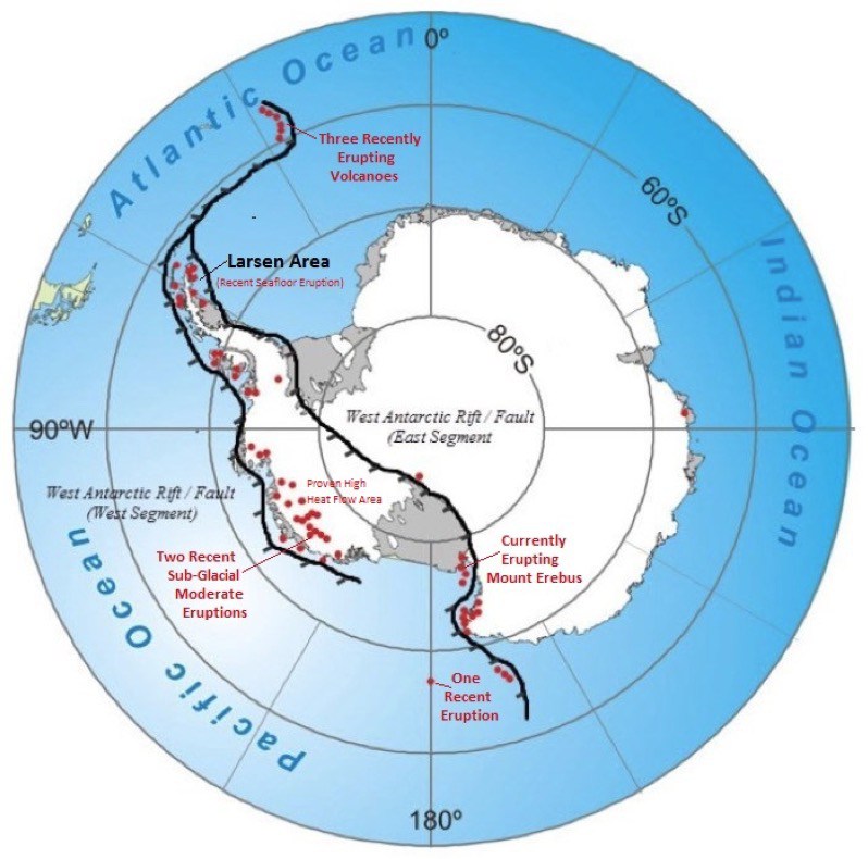
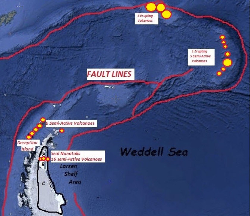
West Antarctica and the Antarctic Peninsula form a connected rift / fault zone that includes about 60 active and semi-active volcanoes, which are shown as red dots in the following map.  

Volcanoes located along the branching West Antarctic Fault/Rift System.
Source:  James Kamis, Plate Climatology, 4 July 2017

In a 29 June 2018 article on the Plate Climatology website, author James Kamis presents evidence that the fault / rift system underlying West Antarctica generates a significant geothermal heat flow into the bedrock and is the source of volcanic eruptions and sub-glacial volcanic activity in the region.  The heat flow into the bedrock and the observed volcanic activity both contribute to the glacial melting observed in the region.  You can read this article here:

http://www.plateclimatology.com/geologic-forces-fueling-west-antarcticas-larsen-ice-shelf-cracks/

The correlation between the locations of the West Antarctic volcanoes and the regions of higher heat flux within the fault / rift system are evident in the following map, which was developed in 2017 by a multi-national team.

Geothermal heat flux distribution at the ice-rock interface superimposed on subglacial topography.  Source:  Martos, et al., Geophysical Research Letter 10.1002/2017GL075609, 30 Nov 2017

The authors note: “Direct observations of heat flux are difficult to obtain in Antarctica, and until now continent-wide heat flux maps have only been derived from low-resolution satellite magnetic and seismological data. We present a high-resolution heat flux map and associated uncertainty derived from spectral analysis of the most advanced continental compilation of airborne magnetic data. …. Our high-resolution heat flux map and its uncertainty distribution provide an important new boundary condition to be used in studies on future subglacial hydrology, ice sheet dynamics, and sea level change.”  This Geophysical Research Letter is available here:  

https://agupubs.onlinelibrary.wiley.com/doi/pdf/10.1002/2017GL075609

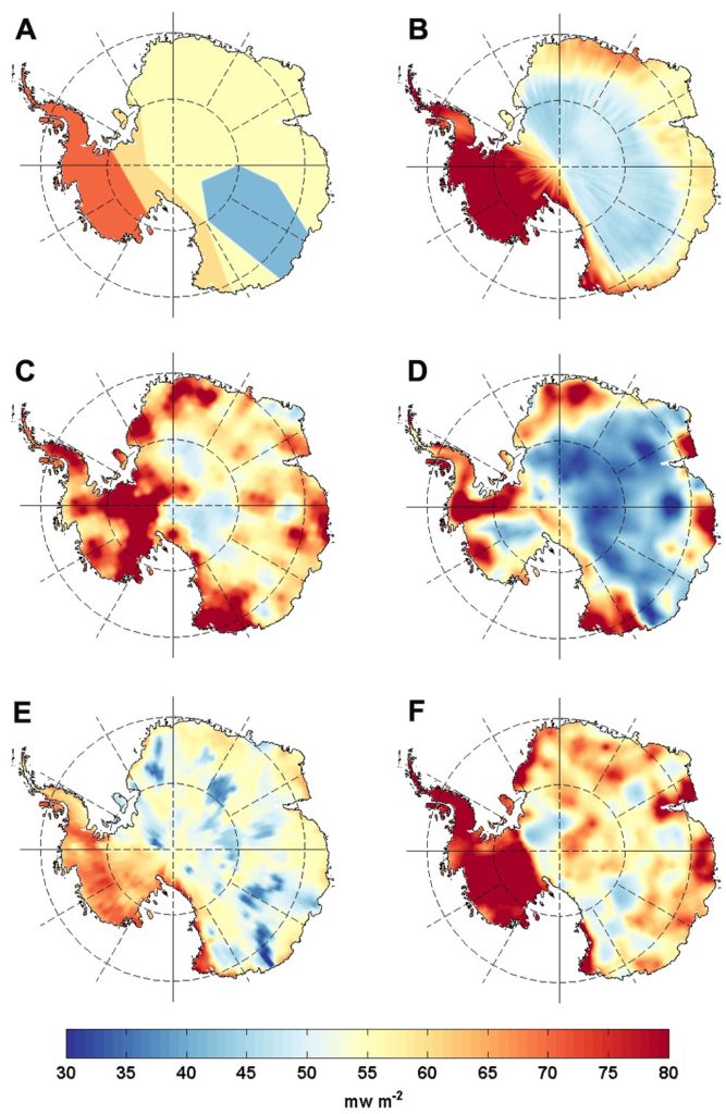
The results of six Antarctic heat flux models developed from 2004 to 2017 were compared by Brice Van Liefferinge in his 2018 PhD thesis.  His results, shown below, are presented on the Cryosphere Sciences website of the European Sciences Union (EGU). 

Spatial distributions of geothermal heat flux: (A) Pollard et al. (2005) constant values, (B) Shapiro and Ritzwoller (2004): seismic model, (C) Fox Maule et al. (2005): magnetic measurements, (D) Purucker (2013): magnetic measurements, (E) An et al. (2015): seismic model and (F) Martos et al. (2017): high resolution magnetic measurements.  Source:  Brice Van Liefferinge (2018) PhD Thesis.

Regarding his comparison of Antarctic heat flux models, Van Liefferinge reported:  

  • “As a result, we know that the geology determines the magnitude of the geothermal heat flux and the geology is not homogeneous underneath the Antarctic Ice Sheet:  West Antarctica and East Antarctica are significantly distinct in their crustal rock formation processes and ages.”
  • “To sum up, although all geothermal heat flux data sets agree on continent scales (with higher values under the West Antarctic ice sheet and lower values under East Antarctica), there is a lot of variability in the predicted geothermal heat flux from one data set to the next on smaller scales. A lot of work remains to be done …” 

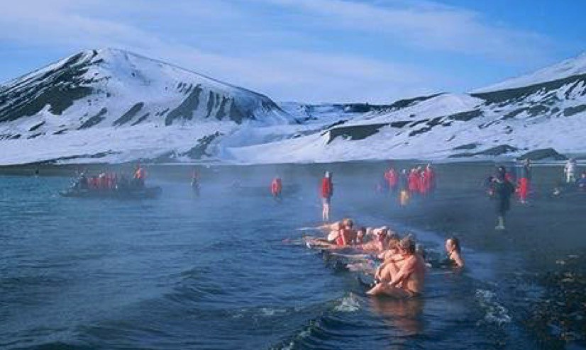
The effects of geothermal heating are particularly noticeable at Deception Island, which is part of a collapsed and still active volcanic crater near the tip of the Antarctic Peninsula.  This high heat flow volcano is in the same major fault zone as the rapidly melting / breaking-up Larsen Ice Shelf.  The following map shows the faults and volcanoes in this region.  

Key geological features in the Larsen “C” sea ice segment area.  
Source:  James Kamis, Plate Climatology, 4 July 2017
Tourists enjoying the geothermally heated ocean water at Deception Island.  
Source: Public domain

So, if you take a cruise to Antarctica and the Cruise Director offers a “polar bear” plunge, I suggest that you wait until the ship arrives at Deception Island.  Remember, this warm water is not due to climate change.  You’re in a volcano.

For more information on Bedmap 2 and BedMachine:

  • “Antarctic Bedrock,” Visualizations by Cindy Starr,  NASA Scientific Visualization Studio, Released on June 4, 2013:  https://svs.gsfc.nasa.gov/4060
  • Morlighem, M., Rignot, E., Binder, T. et al. “Deep glacial troughs and stabilizing ridges unveiled beneath the margins of the Antarctic ice sheet,” Nature Geoscience (2019) doi:10.1038/s41561-019-0510-8:  https://www.nature.com/articles/s41561-019-0510-8

More information on geothermal heating in the West Antarctic rift / fault zone:

200th Anniversary of the Discovery of Antarctica: 28 January 2020

Peter Lobner

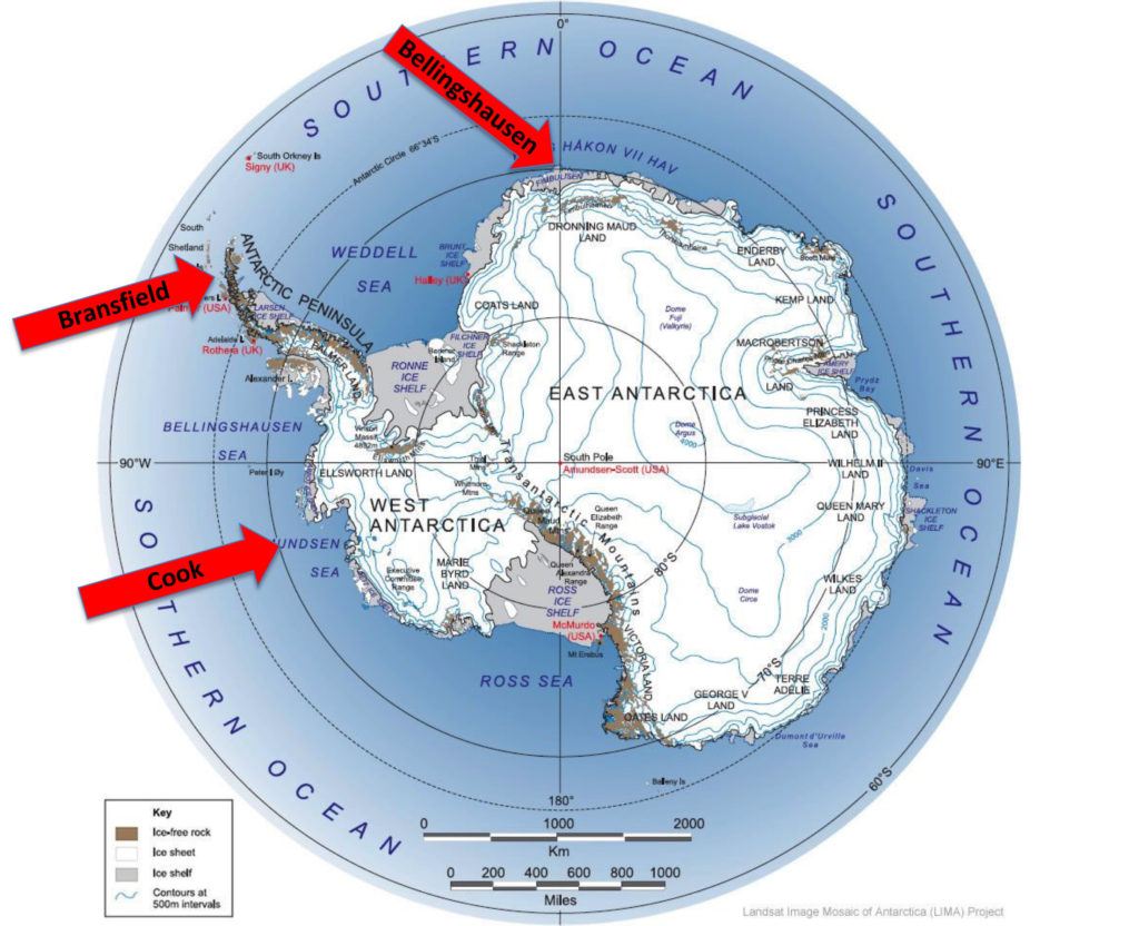
During his second voyage in 1773, British Captain James Cook became the first to cross the Antarctic Circle, but he was turned back by heavy sea ice without ever sighting the coast of Antarctica.  It took 47 years before a Russian expedition, led by Estonian Fabien von Bellingshausen, sighted the coast of Antarctica. As the expedition leader, Bellingshausen generally is credited with the discovery of Antarctica on 28 January 1820.  Just two days later, on 30 January 1820, a British expedition to the South Shetland Islands, led by Irish Lieutenant Edward Bransfield, sighted the tip of the Antarctic Peninsula.  Bransfield is credited by some with the discovery of Antarctica.  In this post, we’ll take a look at the voyages of these three pioneering Antarctic explorers.


Map of Antarctica and the Southern Ocean showing the topography of Antarctica (as blue lines), research stations of the United States and the United Kingdom (in red text), ice-free rock areas (in brown), ice shelves (in gray) and names of the major ocean water bodies (in blue uppercase text).  Source: adapted from LIMA Project (Landsat Image Mosaic of Antarctica) via Wikipedia

Captain James Cook  – First crossing of the Antarctic Circle,  17 January 1773

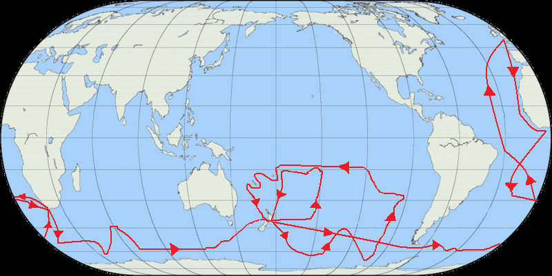
Setting out on their second voyage from England in July 1772, Captain James Cook (1728-1779) and his crew, on His Majesty’s Ship Resolution, circumnavigated the globe travelling as far south as possible to determine whether there actually was a great southern continent.  The route covered during this voyage is shown in the following map.

Route of James Cook’s second voyage.  Source:  Jon Platek via Wikipedia

On 17 January 1773, Cook made the first recorded crossing of the Antarctic Circle, which he reported in his log:

“At about a quarter  past 11 o’clock we cross’d the Antarctic Circle, for at Noon we were by observation four miles and a half south of it and are undoubtedly the first and only ship that ever cross’d that line.”

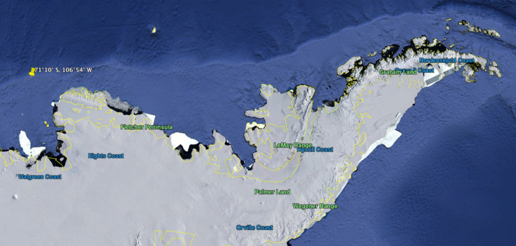
Cook crossed the Antarctic Circle three times during his second voyage.  The last crossing, on 30 January 1773, was to be the most southerly penetration of Antarctic waters, reaching latitude 71°10’ S, longitude 106°54’ W.  The ship was forced back due to solid sea ice.  Cook came within about 240 km (150 mi) of the Antarctic mainland on his second voyage.

Cook’s southernmost approach to Antarctica (yellow pin, left).  Source:  Google Earth

Fabien von Bellingshausen – First sighting of Antarctica, 28 January 1820

In 1818, the Russian Empire, ruled by Czar Alexander I, organized two expeditions to study the polar regions, one for mapping the Arctic and one for sailing further south than Captain James Cook’s second voyage 45 years earlier.  The southern polar expedition was led by the prominent cartographer Fabien Gottlieb Benjamin von Bellingshausen, who was born in 1778 on Saaremaa, the largest island in today’s Republic of Estonia.  This was to became known as the Bellingshausen Expedition. 

The expedition consisted of two ships, Bellingshausen’s 985 ton flagship sloop Vostok, and the 530 ton support sloop Mirnyi, under the command of Mikhail Lazarev (Bellingshausen’s second-in-command).  An exhibit at the Estonian Maritime Museum in Tallinn reported:  “The largest proportion (a whopping 65.8 tons) of the food stock on the Bellingshausen expedition consisted of wheat and rye cookies.  In addition, they brought 28 tons of salted meat and 20.5 tons of dried peas.  In ports, the crew also acquired cereal and fresh food.”  In Antarctic waters, icebergs would supply their fresh water needs.

On 4 June 1819, the expedition departed from the Russian naval island base at Kronstadt, just off the coast from Saint Petersburg. Seven months later, the expedition crossed the Antarctic Circle on 26 January 1820.

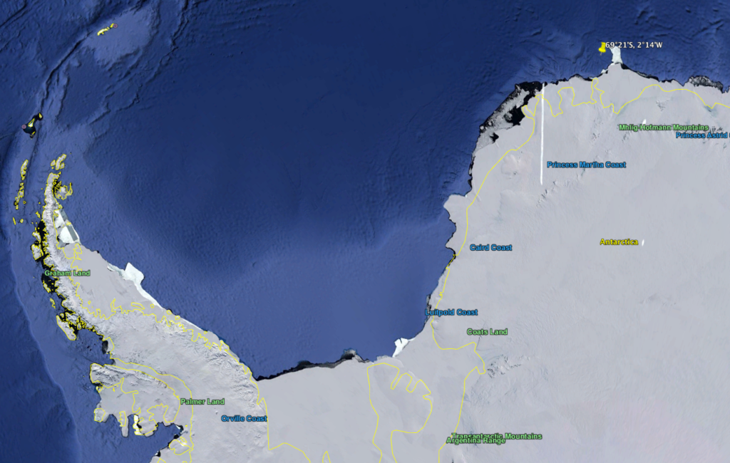
The Bellingshausen expedition is credited with being the first to reach Antarctica on 28 January 1820, when the two ships approached to within 20 miles (32 km) of the Antarctic coast, at latitude 69°21’28” S, longitude 2°14’50” W,  in an area now known as Princess Martha Coast in East Antarctica.  Bellingshausen reported sighting an ice shelf that today is known as the Fimbul ice shelf.

Location of Bellingshausen’s first sighting of Antarctica on 28 January 1820 
(yellow pin, upper right).  Source:  Google Earth

Bellingshausen did not claim to have discovered Antarctica, but his descriptions of what he saw agree very well with what the Princess Martha Coast is now known to look like.  On the basis of this sighting and the coordinates given in his log book, Bellingshausen generally is credited (e.g., the British polar historian A. G. E. Jones) with the discovery of  the Antarctic continent.

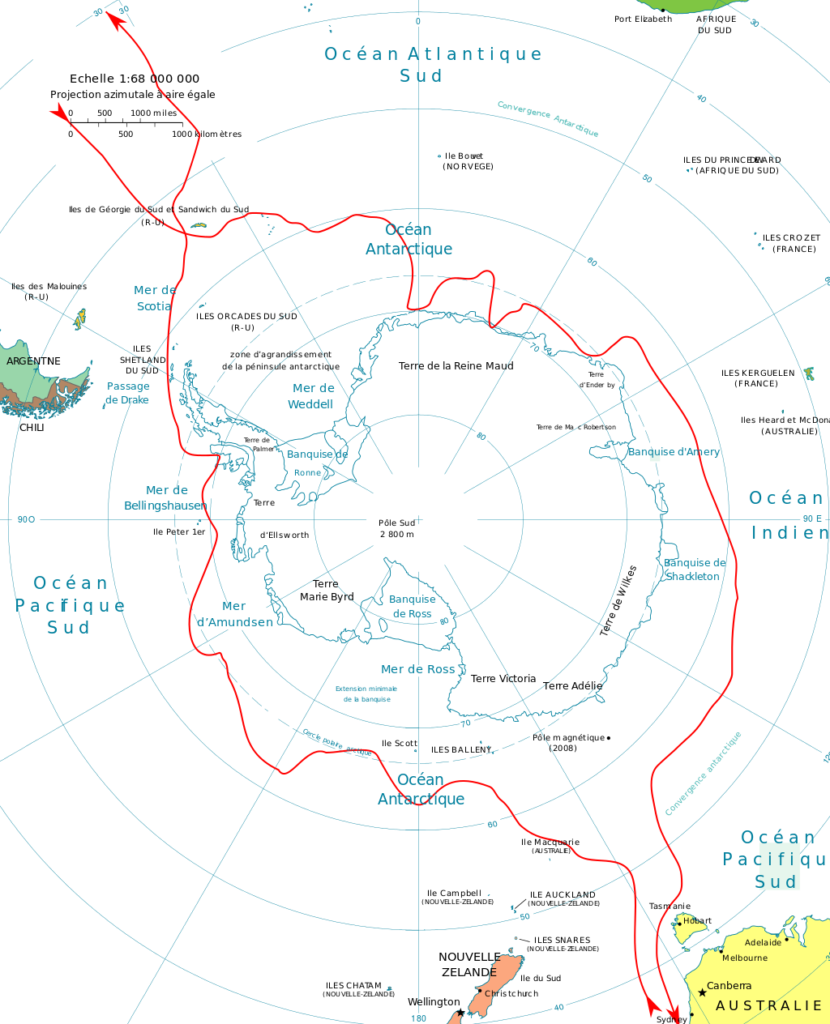
In their subsequent circumnavigation of the Antarctic continent, Bellingshausen and Lazarev became the first explorers to see and officially discover several parts of the Antarctic landmass.   On 22 February 1820, the Vostok and Mirnyi were hit by the worst storm of the voyage and were forced to sail north, arriving in Sydney, Australia in April.  After several months exploring the South Pacific and then hearing about the sighting of Antarctica by the British (Edward Bransfield and William Smith), the Bellingshausen Expedition sailed from Sydney on 11 November 1820 to continue exploring the Antarctic. On 24 December 1820, the two ships once again were south of the Antarctic Circle.  On this part of the voyage, Bellingshausen discovered and named Peter I Island and the Alexander Coast, now known as Alexander Island, along the west coast of the Antarctic Peninsula.

The circumnavigation route followed by the Bellingshausen Expedition is shown in the following map.  Bellingshausen became only the second explorer, after Cook, to have circumnavigated Antarctica.

Route map of the Bellingshausen Expedition to Antarctica: 1819-21.
Source:  Bourrichon via Wikipedia

The Bellingshausen expedition returned to Kronstadt on 4 August 1821, ending a voyage that had lasted two years and 21 days and covered about 50,000 miles (80,467 km).  After his return, Bellingshausen was promoted to the rank of Admiral and Lazarev was promoted to the rank of Lieutenant–Captain.  His travel account was not published until ten years later.

As part of the International Geophysical Year (IGY) in the mid-1950s, the Soviet Union established its first two Antarctic bases, which were named Mirnyi (established 13 February 1956) and Vostok (established 6 December 1957), in honor of the ships in the Bellingshausen Expedition.

2003 Estonian stamp commemorating Bellingshausen’s 
discovery of Antarctica.  Source: eBay

The Bellingshausen expedition was commemorated on a 2003 Estonian stamp that features a portrait of Bellingshausen and a drawing of his flagship Vostok over a map showing the route of his Antarctic expedition.

Edward Bransfield – Sighting of Antarctica, 30 January 1820

In February 1819, British merchant ship owner William Smith, aboard his vessel The Williams, was sailing from Buenos Aires, Argentina to Valparaiso, Chile.   To catch the prevailing winds, he sailed unusually far south of Cape Horn and, on 19 February 1819, sighted previously unknown islands in the Southern Ocean.  To confirm his sighting and to chart the islands, Royal Navy officials in Valpariso chartered his ship and assigned Sailing Master Lieutenant Edward Bransfield, from Ballinacurra, Ireland (near Cork), to accompany Smith on an expedition back to the islands, which would become known as the South Shetland Islands.  During this expedition,  Bransfield landed on King George Island and took formal possession on behalf of King George III.  

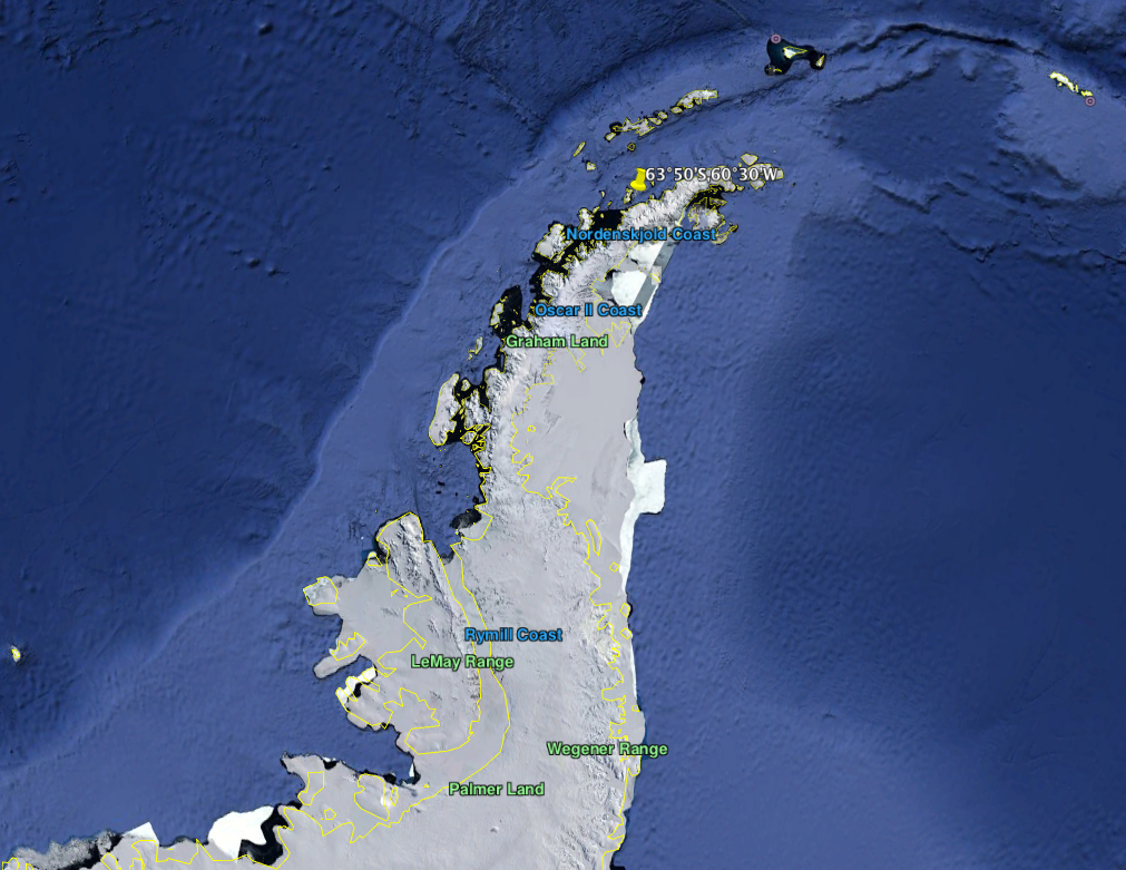
On 30 January 1820, Bransfield sighted the Trinity Peninsula, which is the northernmost tip of the Antarctic Peninsula.  His sighting was made at about latitude 63°50’S and longitude 60°30’W.

Location of Bransfield’s first sighting of Antarctica (yellow pin, top center) on 30 January 1820.  Source:  Google Earth

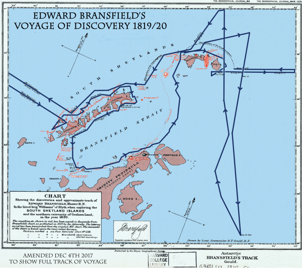
After the initial sighting, Bransfield charted a segment of the Trinity Peninsula and followed the edge of the ice sheet in a north-easterly direction, where he discovered various points on Elephant Island and Clarence Island, which he formally claimed for the British Crown. In his log, Bransfield made a note of two “high mountains, covered with snow”, one of which subsequently was named Mount Bransfield in his honor.  The Bransfield Strait between the South Shetland Islands and the Antarctic Peninsula also was named in his honor in 1822 by Antarctic explorer James Weddell. 

Bransfield’s track in Antarctic.  Source:  Edited version by Jim Wilson, http://rememberingedwardbransfield.ie/voyage-of-discovery/

Since Bransfield’s sighting, the tip of the Antarctic Peninsula has been known variously as Trinity Land, Palmer Land, Graham Land, and Land of Louis Philippe.  Prime Head is the northernmost point of this peninsula. 

Bransfield’s expedition charts were given to the Admirality and currently are in the possession of the UK Hydrographic department in Taunton, Somerset.

In 2000, Bransfield’s historic achievement was recognized when the Royal Mail issued a stamp in his honor. Since no likeness of the man survives, the stamp depicted an image of the RRS Bransfield, a British Antarctic surveying vessel.

2000 Royal Mail commemorative stamp. 
Source: Commonwealth Stamps Opinion

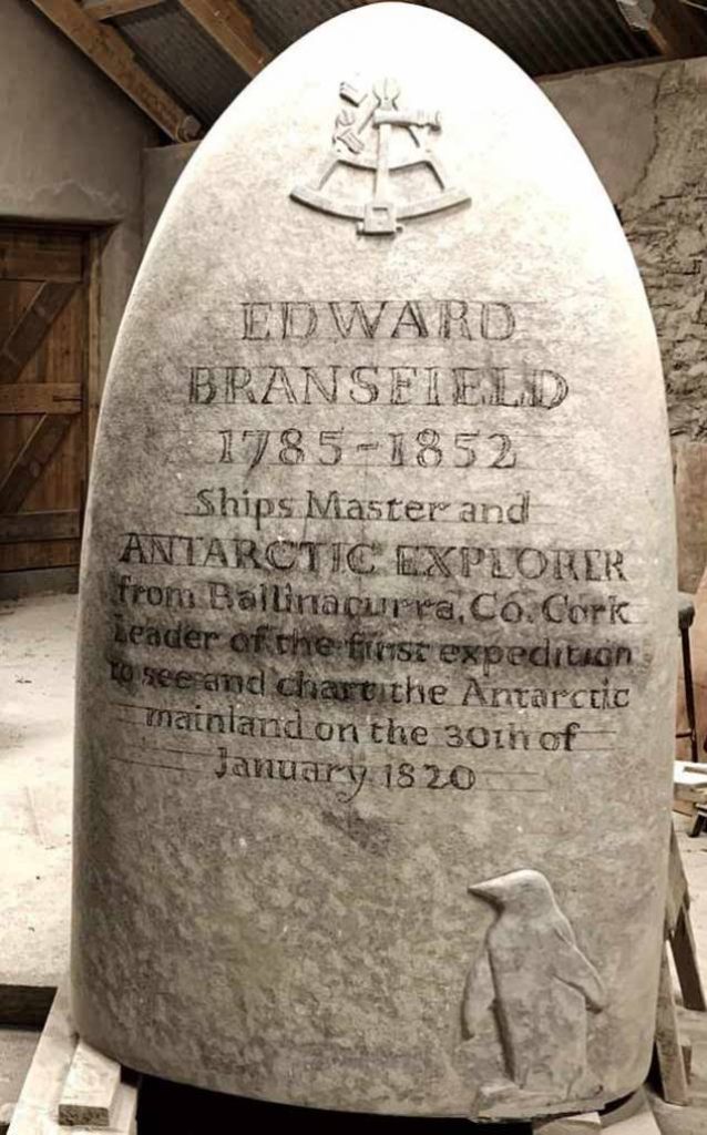
To commemorate the 200th anniversary of Edward Bransfield’s sighting of Antarctica (and some say, his discovery of Antarctica), a memorial by sculptor Matt Thompson will be erected in Ballinacurra, Ireland in January 2020.

Edward Bransfield memorial, work in progress.
Source: Tony Whelan photo, Afloat.ie

Estonia’s Antarktika 200 expedition

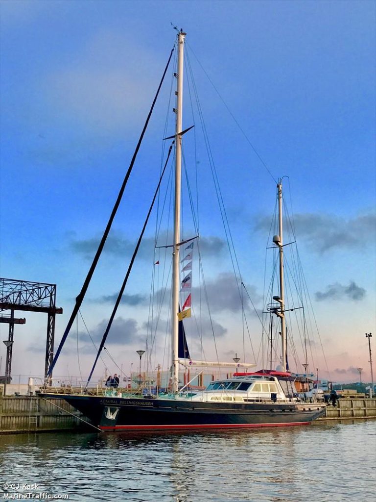
To commemorate the 200th anniversary of the discovery of Antarctica by the Bellingshausen Expedition, the Estonian Maritime Museum and NGO Thetis Expeditions have organized a scientific expedition from Kronstadt, Russia to the Antarctic peninsula by a crew of 12 aboard the 24 meter, 95 ton, Estonian-registered sailing yacht S/Y Admiral Bellingshausen.

S/Y Admiral Bellingshausen.
Source: maritimetraffic.com

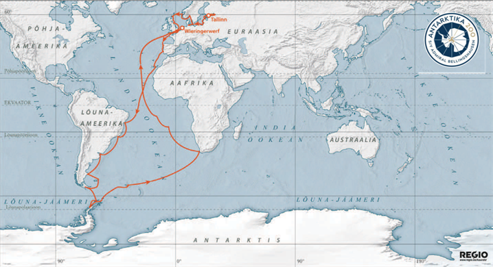
The planned route, which includes about 50 stops, and approximately follows the Bellingshausen’s route to and from the Southern Ocean, is shown in the following map.  The crew will take samples of pollen, water and microplastics while on the voyage, for researchers at Estonia’s University of Tartu.  The expedition includes food of Estonian origin to the largest possible extent, and probably a better selection of food than on Bellingshausen’s 1819 – 1821 voyage.

Antarktika 200 route map.  Source: International Maritime Rescue Federation

The ship departed Tallinn harbor on 14 July 2019, and headed for its first port of call at the historic Russian naval island base at Kronstadt, which was the starting point for the Bellingshausen Expedition.  

You can follow the current position on the S/Y Admiral Bellingham at the following link:

https://www.marinetraffic.com/en/ais/details/ships/shipid:5929279

On 3 January 2020, the ship was moored in Ushuaia, Argentina, in preparation for its voyage across the Drake Passage to Antarctica.  The ship is scheduled to reach Antarctica in time to celebrate the 200th anniversary of Bellingshausen’s discovery on 28 January 2020.

This voyage will be the subject of a TV documentary.  For more information on the Antarktika 200 expedition, visit the following website:

https://www.international-maritime-rescue.org/news/the-estonian-maritime-expedition-to-celebrate-the-discovery-of-antarctica-200-years-ago

Best wishes to the crew of S/Y Admiral Bellingshausen for a safe and successful voyage.

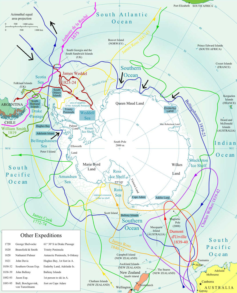
Composite map of early expeditions in Antarctic waters

The following map provides a good overview of the routes taken by the early Antarctic explorers, none of whom went ashore.  

Source: Antarctic Logistics

The first landings in Antarctica

An unconfirmed first landing at Hughes Bay, on the northwest coast of the Antarctic Peninsula, may have been made on 7 February 1821 by Captain John Davis and crew members from the American sealing ship Cecilia, which had been sailing in the vicinity of the South Shetland Islands in search of seals. The ship’s log recorded that men were ashore to look for seals at latitude 64°01’S.  The logbook entry concluded with the statement, “I think this Southern Land to be a Continent.”

The first substantiated landing in Antarctica was not made until 74 years later, on 24 January 1895, when seven men from the Norwegian whaling and sealing ship Antarctic, came ashore in the vicinity of Cape Adare, on the Ross Sea almost due south of New Zealand.  New Zealander Alexander Francis Henry von Tunzelmann is sometimes credited as being the first person to set foot on the Antarctic mainland.

For more information on Fabien Bellingshausen & Mikhail Lazarev

Fabien Gottlieb Von Bellingshausen (1778-1852):  https://antarctic-logistics.com/2010/08/28/fabian-gottlieb-von-bellingshausen/

Mikhail Lazarev (1788-1851):  https://antarctic-logistics.com/2010/08/28/mikhail-lazarev/

For more information on Edward Bransfield:

Remembering Edward Bransfield:  http://rememberingedwardbransfield.ie

Celebrate Isaac Asimov’s Centennial by Reading Some of His Fabulous Books (Again)

Peter Lobner

The birthdate of Isaac Asimov, a famous author best known for his science fiction novels and short stories, is sometime between 4 October 1919 and 2 January 1920.  He was born in Petrovichi in Smolensk Oblast, RSFSR (now Russia), west of Moscow, near the border with Belarus, and he died in New York City on 6 April 1992.  He traditionally celebrated his birthday on 2 January, giving enough reason to mark the centennial of his birth on 2 January 2020. 

You’ll find short biographies of Isaac Asimov at the following links:

https://www.biography.com/writer/isaac-asimov

and: 

https://www.notablebiographies.com/An-Ba/Asimov-Isaac.html

Left: Isaac Asimov circa 1959 (Wikipedia)
Right:  Asimov circa 1980s (Goodreads.com)

I was an avid reader of science fiction during the time when Isaac Asimov’s novels on robots, the Foundation and the Galactic Empire were first being published.  I  was hooked with the first novel I read,  Pebble in the Sky, and waited with anticipation until each new book became available in paperback.

You may remember that Asimov created the basic three laws of robotics:

  1. A robot may not injure a human being or, through inaction, allow a human being to come to harm.
  2. A robot must obey the orders given it by human beings except where such orders would conflict with the First Law.
  3. A robot must protect its own existence as long as such protection does not conflict with the First or Second Laws.

These laws were woven into the storyline of many of his books.

Unless you already have your favorite Asimov volumes on your bookshelf, I suggest that you visit the Internet Archive and the Open Library, which provide free access to many Asimov books as well as a vast range of other books and resources.  You can set up a free account on the Internet Archive homepage here:

https://archive.org

Log in and you’ll have access to many of Asimov’s books:

In the Open Library, a search for “Isaac Asimov” will take you here:

https://openlibrary.org/authors/OL34221A/Isaac_Asimov

Now you’re almost ready to look for an available book in the Open Library and start reading.  Note that you may be in a waitlist, because library rules for e-books limit the number of copies that can be checked out at any one time.

If you choose to read about robots, the Foundation and the Galactic Empire (books written over a 52 year period from 1940 to 1992), consider Asimov’s own recommendations regarding the chronological order of the stories, in terms of future history: 

  • The Complete Robot (1982).  This is a collection of 31 robot short stories published between 1940 and 1976 and includes every story in Asimov’s earlier collection: I, Robot (1950).  
  • The Positronic Man (1992):  A stand-alone robot novel set from the 22nd to 24th centuries, co-written with Robert Silverberg, based on Asimov’s 1976 novelette “The Bicentennial Man”
  • Nemesis (1989): A standalone novel, set in the 23rd century in a star system about 2 light years from Earth, when interstellar travel was new
  • Caves of Steel (1954).  This is the 1st  robot novel. 
  • The Naked Sun (1957).  This is the 2nd robot novel. 
  • The Robots of Dawn (1983).  This is the 3rd robot novel.    
  • Robots and Empire (1985).  This is the 4th robot novel.    
  • The Currents of Space (1952).  This is the 1st Empire novel. 
  • The Stars, Like Dust (1951).  This is the 2nd Empire novel.   
  • Pebble in the Sky (1950).  This was Asimov’s first novel.  It is the 3rd Empire novel.     
  • Prelude to Foundation (1988):  This is the 1st Foundation novel, actually a prequel.
  • Forward the Foundation (1992):  Published posthumously, this is the 2nd  Foundation novel, and the 2nd prequel.
  • Foundation (1951).  This is the 3rd Foundation novel.  It is a collection of four stories published between 1942 and 1944, plus an introductory section written in 1949.  
  • Foundation and Empire (1952).  This is the 4th Foundation novel. It is made up of two stories originally published in 1945.
  • Second Foundation (1953): This is the 5th Foundation novel. It is made up of two stories originally published in 1948 and 1949.
  • Foundation’s Edge (1982):  This is the 6th Empire novel.  
  • Foundation and Earth (1986): This is the 7th Empire novel. 
  • The End of Eternity (1955): A standalone novel, about Eternity, an organization “outside time” which aims to improve human happiness by altering history. 

The above list is adapted and updated from the Author’s notes in Prelude to Foundation to account for books published after 1988.

I also recommend that you take the time to watch the following on YouTube:

Search YouTube and you’ll find more Asimov audiobooks. 

Thank you, Isaac Asimov, for inspiring generations of readers, and generations yet to come.

Many European Union (EU) “Green Deal” Energy Advocates are Hypocrites

Updated 16 December 2019, 20 March & 5 May 2020

Peter Lobner

In a 12 December 2019 NUCNET article, David Dalton, reporting on the United Nations Framework Convention on Climate Change (COP25) in Madrid, summarized the following points made by International Atomic Energy Agency (IAEA) director-general Rafael Mariano Grossi:

  • The world is “well off the mark” from reaching the climate goals of the Paris Agreement.
  • Around two-thirds of the world’s electricity still is generated through burning fossil fuels.
  • Greater use of low-carbon nuclear power is needed to ensure the global transition to clean energy includes a baseload backup to variable renewable energy sources such as solar and wind.
  • Greater deployment of a diverse mix of low-carbon sources such as hydro, wind and solar, as well as nuclear power, and battery storage, will be needed to reverse that trend and set the world on track to meet climate goals.

I concur with these points and feel that Mr. Grossi has laid out a reasonable and responsible position on the future role of nuclear power in “green” energy solutions that are focused on the primary goal of  reducing worldwide carbon dioxide emissions.  The commercial nuclear power industry has demonstrated the ability to reliably generate carbon-free electricity, 24 hours a day, seven days a week, in units of a thousand megawatts or more per power plant.  Except for the largest hydroelectric facilities, no other component of a carbon-neutral energy infrastructure offers such capabilities, which are essential for delivering 24/7 service to large users and stabilizing the grid.  Unfortunately, Mr. Grossi’s view is not shared by many EU energy advocates seeking to get member states to agree to the EU “Green Deal.”

You can read David Dalton’s complete article here:  https://www.nucnet.org/news/nuclear-and-renewables-are-not-in-competition-with-each-other-12-4-2019

The EU Energy Union and the “Green Deal”

The European Energy Union is the implementation of the 2019 Juncker Commission’s Priority #3 recommendation for a resilient energy union with a forward-looking climate change policy.  You can read a summary of the Commission’s recommendations here: http://www.europarl.europa.eu/RegData/etudes/IDAN/2019/637943/EPRS_IDA(2019)637943_EN.pdf

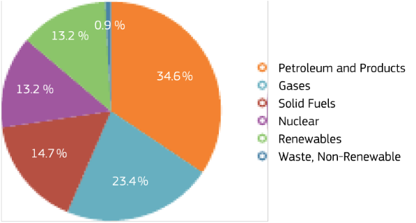
The Energy Union has quite a challenge, starting with the EU’s energy mix (circa 2016) as shown in the following chart:

EU 2016 energy mix.  Source:  EU Statistical Pocketbook 2018

Complicating matters, the EU currently imports nearly 40% of its natural gas from Russia. 

The European Union’s Green Deal is described as “a new growth strategy that aims to transform the EU into a fair and prosperous society, with a modern, resource-efficient and competitive economy where there are no net emissions of greenhouse gases in 2050 and where economic growth is decoupled from resource use.”  You’ll find the EU’s 11 December 2019 detailed description of the Green Deal here: https://eur-lex.europa.eu/legal-content/EN/TXT/?qid=1576150542719&uri=COM%3A2019%3A640%3AFIN

For more information, see the EU “Green Deal” website here: https://ec.europa.eu/info/index_en

To enforce this “Green Deal,” the EU intends to adopt a “climate law” that is scheduled to be presented to Member States in March 2020.

The EU’s “Green Deal” is strongly biased against almost anything except renewable energy sources

On 11 December 2019, Reuters reported that, “European Union states have blocked a set of new rules governing which financial products can be called ‘green’ and ‘sustainable’, EU officials said, in a major setback for the bloc’s climate ambitions.”  The Reuters report noted that EU lawmakers wanted nuclear and fossil fuel funding clearly excluded from the definition of “green” investments. You can read this Reuters report here: https://af.reuters.com/article/commoditiesNews/idAFL8N28L3GD

This EU position is a particular problem for France, where nuclear power provided 71.7% of total French generating capacity in 2018 and about 90% of total electrical capacity was provided by low-carbon sources (nuclear + renewables).  In October 2019, Électricité de France announced that it is planning to make a decision in 2021 on building several more large nuclear power plants, which will be needed in the next decade as its oldest 900 MWe pressurized water reactor (PWR) plants start reaching their retirement age.

In contrast, nuclear power provided 11.8% of total German generating capacity in 2018 and about 47% of total electrical capacity was provided by low-carbon sources (nuclear + renewables), while 48.3% of total generating capacity was provided by a fossil fuel sources.  Germany plans to decommission the last of its seven remaining nuclear power plants, representing an aggregate of 9,256 MWe of carbon-free electric generating capacity, in the next three years, by December 2022.  It will be a challenge for new renewable energy sources to be deployed in time to make up for the lost carbon-free generating capacity from nuclear power.  It is notable that Germany gets 7% of its total generating capacity from burning biomass, which the EU, in its great wisdom, defines as a carbon-neutral renewable energy source.  More on that later.

How does the EU define “clean energy”?

The EU’s definition of “clean energy” is rather elusive.  On the EU Green Deal website, the Clean Energy fact sheet identifies the following three “key principle:” 

  • Prioritize energy efficiency and develop a power sector based largely on renewable sources
  • Secure and affordable EU energy supply
  • Fully integrated, interconnected and digitalized EU energy market

Only “renewable sources” are actually defined as sources for “clean energy.”  Nuclear power is not identified as a “clean” energy source.  I was unable to find on the EU Green Deal website any performance metrics related to “clean” energy source performance relative to carbon emissions.

Here’s the link to the EU Clean Energy Fact Sheet:  https://ec.europa.eu/commission/presscorner/detail/en/fs_19_6723

Another EU description of “clean energy” can be found the “Clean Energy for all Europeans” program, which focuses on the following:

  • Energy efficiency first, focusing on energy saving opportunities and “smarter” / “greener” buildings.
  • More renewables, with a new target of at least 32% in renewable energy by 2030
  • Better governance of the Energy Union, including a new energy “rulebook” under which each EU Member State drafts a National Energy and Climate Plan (NECP)
  • More rights for consumers to produce, store or sell their own energy
  • Smarter and more efficient electricity market

The Clean Energy for all Europeans program is described here: https://ec.europa.eu/info/news/clean-energy-all-europeans-package-completed-good-consumers-good-growth-and-jobs-and-good-planet-2019-may-22_en

The focus is on a distributed electric power infrastructure that takes advantage of many ways to improve energy efficiency, manage power consumption and generate power from distributed renewable energy sources.  Nuclear power is not mentioned at all in this document.  However, “large scale biopower” from agricultural and forest sources is addressed. 

How does the EU define “renewable energy sources”?

The latest EU directive on the promotion of energy use from renewable sources is Directive (EU) 2018/2001, dated 11 December 2018.  The definition of “renewable energy sources” traces back to Directive 2003/54/EC, dated 26 June 2003:

“Renewable energy sources” means renewable non-fossil energy sources (wind, solar, geothermal, wave, tidal, hydropower, biomass, landfill gas, sewage treatment plant gas and biogases)

So, fossil energy sources are excluded and nuclear energy sources are not included.

This seems logical but the devil is in the details.  The main problem is that EU energy policy equates “renewable” with being “carbon free,” when, for some renewable energy sources, this is far from the truth.  As an example, existing EU policy treats burning wood fuel in power plants as carbon-neutral while this fuel generates 15 to 20% more carbon dioxide per megawatt than the coal fuel it replaces.  This has resulted in a trend among EU coal-burning power plants to switch to wood pellets and claim the emission credit while actually polluting more than before.  See my 7 January 2017 post, “Hey, EU!! Wood may be a Renewable Energy Source, but it isn’t a Clean Energy Source,” for details.  The direct link to this post is here: https://lynceans.org/all-posts/hey-eu-wood-may-be-a-renewable-energy-source-but-it-isnt-a-clean-energy-source/

Fortunately, this matter may be on its way to being addressed in an EU court.  A 4 March 2019 article by Karen Savage, writing for Climate Liability News, reports, “The suit, which was filed in the European General Court in Luxembourg, asks the court to prevent EU countries from counting forest wood as a renewable energy source under the 2018 revised Renewable Energy Directive known as RED II.”  Major sources of wood pellets used in EU power plants are in the southeast U.S., where greatly increased logging activities are depleting established, slow-growth hardwood forests.  So the EU is OK with a “clean” energy policy that, in practice, increases current pollution locally in the EU while simultaneously stripping hardwood forests in a location outside of the EU. It seems to me that this is an environmental “double whammy” that can only make sense on paper, but not in practice.  You can read Karen Savage’s article here: https://www.climateliabilitynews.org/2019/03/04/biomass-european-union-lawsuit/

Conclusions

Regarding the EU Green Deal and Energy Union, I’m certain that the devil is in the details, and EU Member States need to have the opportunity to assess these details so there is no misunderstanding when EU climate laws are passed.  

The EU’s Green Deal has major flaws and needs to be recast to acknowledge the important role that nuclear power can play as a large, carbon-free source of electric power while also helping to ensure 24/7 grid stability.  Failing to recognize the role of nuclear power as a carbon-free source of electric power will serve to highlight the strong bias and hypocrisy of an EU energy leadership that has lost its way.  It also would serve as another example of why Brexit makes sense.

Even fossil power, with appropriate advanced environmental controls, should have a role in the Green Deal.  For example, a rapid shift away from coal to natural gas would significantly decrease near-term carbon dioxide emissions.  Similarly, abandoning the laughable EU policy on “carbon-neutral” biomass would eliminate a significant source of carbon dioxide emissions within the EU, and it would save environmentally valuable hardwood forests in the southeast U.S. and elsewhere.

Update: 16 December 2019 – Finally, some common sense prevailed, but only under very intense political pressure and, probably, fear of failure

In an article by Samuel Petrequin, “EU leaders include nuclear energy in green transition,” the Associated Press reported: 

“EU heads of state and government agreed that nuclear energy will be recognized as a way to fight climate change as part of a deal that endorsed the climate target. While Poland did not immediately agree to the plan, the concessions on nuclear energy were enough for the Czech Republic and Hungary to give their approval.  The two nations had the support of France, which relies on nuclear power for 60% of its electricity. They managed to break the resistance of skeptical countries, including Luxembourg, Austria and Germany to get a clear reference to nuclear power in the meeting’s conclusions. ‘Nuclear energy is clean energy,’ Czech Prime Minister Andrej Babiš said. ‘I don’t know why people have a problem with this.’”

You can read the complete AP article here: https://apnews.com/faae3503fe497af36e8d2e9a4d13b62a

The European Council memorandum contains only a single reference to “nuclear,” more in the form of a resigned acknowledgement rather than an endorsement.  

“The European Council acknowledges the need to ensure energy security and to respect the right of the Member States to decide on their energy mix and to choose the most appropriate technologies. Some Member States have indicated that they use nuclear energy as part of their national energy mix.”

You can read the European Council memorandum here: https://www.consilium.europa.eu/media/41768/12-euco-final-conclusions-en.pdf

Congratulations to the representatives from France, Czech Republic, Hungary, Poland and others for fighting the hard political fight and winning a place for nuclear power in the EU’s Green Deal.  But be watchful because the EU anti-nuclear forces are still there.

Update:  20 March 2020 – Yes, the EU anti-nuclear forces are still there.

On 10 March 2020 the European Commission issued a press release announcing its new industrial strategy, “Making Europe’s businesses future-ready: A new Industrial Strategy for a globally competitive, green and digital Europe.”  You can read the press release and download related documents here:  https://ec.europa.eu/commission/presscorner/detail/en/ip_20_416

While the plan highlights the need to “secure a sufficient and constant supply of low-carbon energy at competitive prices,” the word “nuclear” is notably absent from the EU’s industrial strategy.  Not much of a surprise, considering the EU’s behavior on the Green New Deal.

The next day, on 11 March, the Brussels-based nuclear industry group Foratom called on the EU decision-makers to support the nuclear sector’s important role within the EU economy.  Foratom’s Director General,  Yves Desbazeille, noted, “Not only is it (nuclear) low-carbon, it is also flexible, dispatchable and cost-effective”.

Foratom highlighted the following key attributes of nuclear energy in the context of the EU industrial strategy:

  • Maintain the competitiveness of Europe’s industry as energy often accounts for a significant share of manufacturing costs,
  • Decarbonize industry and thus contribute towards the 2050 carbon neutrality target,
  • Provide industry with the energy it needs when it needs it, which is particularly important for processes which run 24/7,
  • Other industries by offering alternative sources of decarbonized energy such as hydrogen and heat (sector coupling).

You can read Foratom’s complete statement here: https://www.foratom.org/press-release/foratom-calls-for-the-eu-to-recognise-nuclear-as-a-strategic-industry/

This is further evidence that EU nuclear energy advocates are fighting an uphill battle for recognition by the entrenched EU bureaucracy that nuclear power is a zero-carbon source of power and it can make an important (and maybe essential) contribution to meeting the EU’s 2050 carbon neutrality goal.

Best wishes to Foratom in their efforts to secure a place in the EU industrial strategy for nuclear power.

Update 5 May 2020 – More support for EU nuclear power

SNETP (Sustainable Nuclear Energy Technology Platform) was established in 2007, with EC support, as a group of non-governmental organizations that promote and coordinate research on nuclear fission.  

On 24 April 2020, SNETP sent a letter, endorsed by more than 100 organizations, to the Vice-presidents of the European Commission and the EU Commissioner for Energy calling for a “just and timely assessment of nuclear energy in the EU Taxonomy of Sustainable Finance.”

When enacted, the EU’sTaxonomy Regulation is intended to be a tool to guide future energy investments by providing investors with information on which activities and technologies contribute to the EU’s sustainability goals.  In their March 2020 final recommendations, the technical expert group (TEG) currently advising the EC on sustainable energy finance did not include nuclear power as a low-carbon and sustainable electricity source.

You can download the SNETP letter and see the logos of the many endorsing organizations here:  http://www.snetp.eu/wp-content/uploads/2020/04/NGO-Civil-society-on-Taxonomy-2020.pdf

Clearly, the battle lines have formed, with the anti-nuclear elements of the EU bureaucracy on one side and organizations like Foratom and SNETP on the other.  Against the behemoth EU bureaucracy, my best wishes go out to the underdogs, Foratom, SNETP, and other organizations and individuals that understand how nuclear power can play important roles in helping the EU achieve climate neutrality by 2050.

For more information:

Land Speed Record Lows and Highs in 2019

Updated 24 July 2020

Peter Lobner

My 11 December 2018 post, “Lots of Land Speed Record (LSR) Action in 2018,” provides background information on land speed record governance and a look at the fastest cars competing in the 2018 LSR season.  2018 highlights included:

  • The North American Eagle team, with driver Jessi Combs, continued to extend the performance of their jet-powered LSR car on a track in the Alvord Desert in Oregon.
  • The Bloodhound team in the UK was saved from insolvency, literally at the last moment, when the business and assets were bought by Yorkshire-based entrepreneur Ian Warhurst.
  • Salt conditions at the Bonneville salt flats in Utah were very good and many speed records were broken.

You can read this 2018 post here: https://lynceans.org/all-posts/lots-of-land-speed-record-lsr-action-in-2018/

2019 was a very different year.

  • The North American Eagle LSR car crashed during a high-speed run in the Alvord Desert in August, killing driver Jessi Combs.
  • The salt conditions at the Bonneville salt flats were poor, resulting in rough driving conditions and generally lower speeds during Bonneville Speed Week (August) and the Utah Salt Flats Racing Association (USFRA) World of Speed (September).  The Bonneville World Finals (October) were cancelled because of wet conditions.
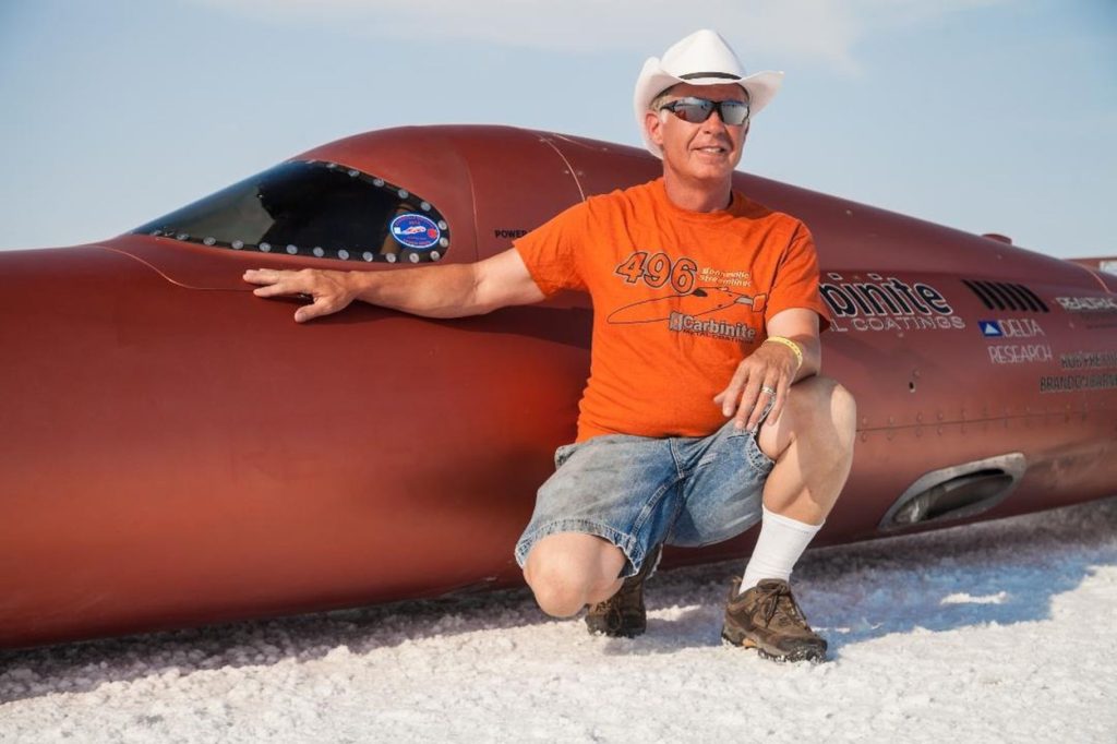
  • The Carbinite LSR car, the Carbiliner, crashed during a high-speed run at the World of Speed 2019 in September, severely injuring driver Rob Freyvogel.
  • The 29th Annual Speed Week at Lake Gairdner, Australia in March had only one run over 300 mph (483 kph) in hot, dry conditions.
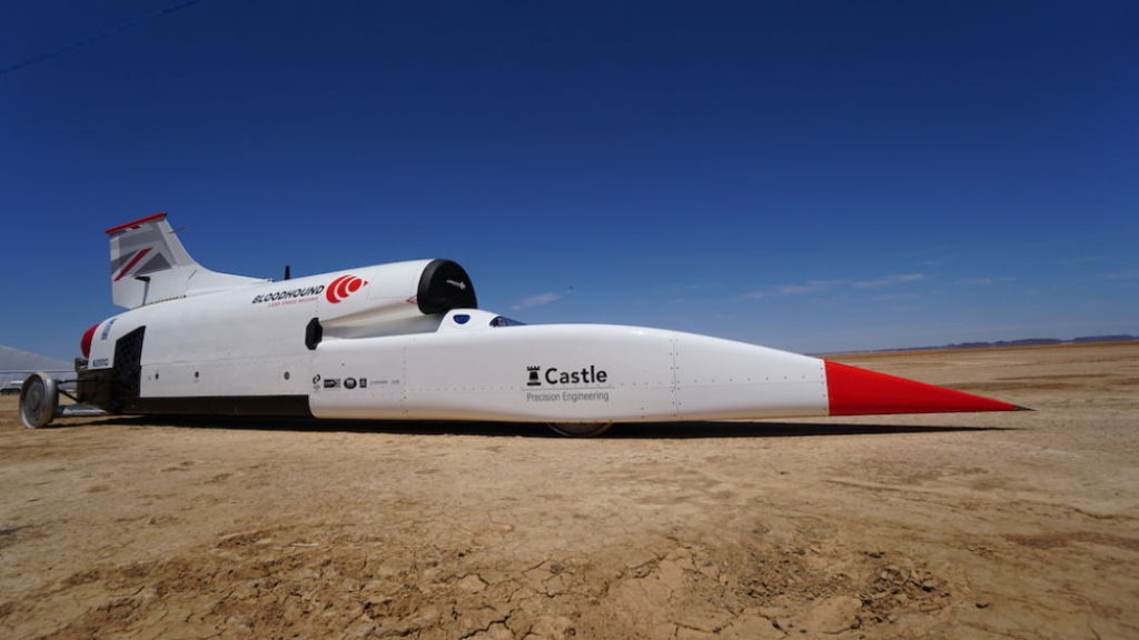
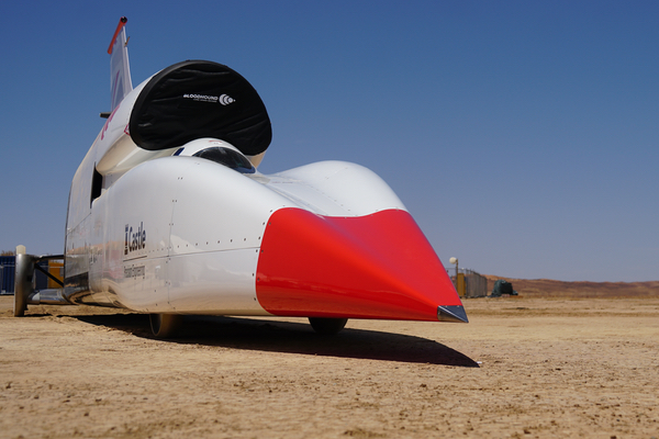
  • Now with proper financing, the Bloodhound LSR team transitioned to the next phase of the project, arriving at the Hakskeen Pan track in South Africa in October and conducting high-speed testing, which concluded successfully in November.

Let’s take a look at the 2019 LSR season in more detail.

1. North American Eagle

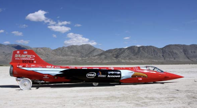
In August 2019, the North American Eagle team, with driver Jessi Combs, returned to the Alvord Desert in Oregon to attempt to break the official Women’s Land Speed Record set by Kitty O’Neil in 1976 with a two-way average speed of 512.710 mph (825.127 kph) in the rocket-powered SMI Motivator at the same venue.  The North American Eagle team website is here:  https://www.landspeed.com

The North American Eagle land speed record car.
Source:  North American Eagle
Driver Jessi Combs.  Source:  North American Eagle

Jessi Combs’s first run on the morning of 27 August 2019 achieved a speed of 515.346 mph (829.369 kph).  On the second run, the North American Eagle crashed near the end of the run, killing Jessi Combs. You can watch a short video of this final run, excluding the crash, here: https://www.tmz.com/2019/09/04/jessi-combs-dead-died-jet-car-video-crash-photos-land-speed-record/

An investigation into the cause of the crash revealed that the front wheel assembly of the car collapsed, possibly due to collision damage from hitting something on the track at high speed.  

North American Eagle Crew Chief Les Holm reported Jessi Combs’ second run was measured at a speed of 548.342 mph (882.471 kph), yielding a two-way average speed of 531.889 mph (855.992 kph).  Hemmings news reported that the North American Eagle team has submitted Jessi Combs’s two-way average speed results to the Guinness Book of World Records to claim the title of fastest woman on the planet.  

It is not yet known if Jessi Combs’ two-way average speed will qualify as an official FIA world land speed record.

The Petersen Automotive Museum in Los Angeles held an exhibition entitled “Jessi Combs: Life at Full Speed” to commemorate the life and accomplishments of this extraordinary person.

Source:  Petersen Automotive Museum

The Jessi Combs Foundation was founded in 2019. The mission of the Foundation is to “educate, inspire and empower the next generation of female trailblazers and stereotype-breakers.”  The Foundation’s website is here: https://www.thejessicombsfoundation.com/mission-statement/

Jessie Combs in North American Eagle.  
Source:  https://www.facebook.com/JessiCombsOfficial/

In June 2020, the Guinness World Record was posthumously awarded to Jessi Combs, declaring:  “The fastest land speed record (female) is 841.338 kph (522.783 mph), and was achieved by Jessi Combs (USA) in the Alvord Desert, Oregon, USA, on 27 August 2019. Jessi is the first person to break this record in more than 40 years.”  This record is posted on the Guinness World Records website here: https://www.guinnessworldrecords.com/world-records/fastest-land-speed-record-(female)

2. Bonneville Speed Week 2019:  13 – 15 August 2019

Summer storms resulted in poor track conditions at Bonneville in 2019, with the salt wet enough to delay the start of Speed Week and then limit the performance of teams that were able to run.  You’ll find a more detailed description of track conditions here:  https://journal.classiccars.com/2019/08/24/they-came-they-saw-but-weather-ruled-at-bonneville/

The Southern California Timing Association’s (SCTA) Speed Week 2019 results are posted here:  http://www.scta-bni.org/2019-sw-race-results.html

Now let’s look at a few of the top challengers at Speed Week 2019.

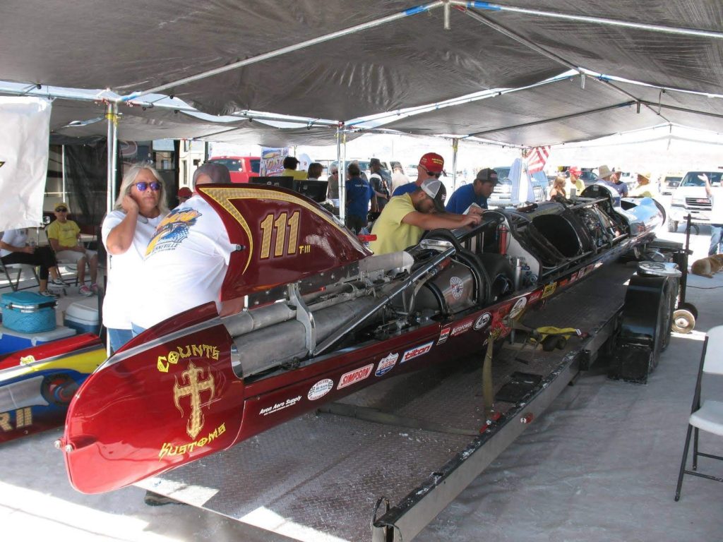
Turbinator II

At the Bonneville World Finals in 2018, Team Vesco’s gas turbine powered Turbinator II, with Dave Spangler driving, made a one-way run through the measured mile of 493.996 mph (795.009 kph), with an exit speed of 503.332 mph (810.034 kph). Turbinator II became the world’s first wheel-driven vehicle to exceed 500 mph and 800 kph.

In 2019, Dave Spangler was unable to complete a single run with Turbinator II during Bonneville Speed Week 2019. Three runs on the 2-mile “short” course were attempted on 14 – 15 August, but none were completed, for a variety of issues.  You can watch a short video about Team Vesco at Speed Week 2019 here:

Turbinator II in the pits, 12 August 2019.  Source:  Gregg Adams photo via http://www.scta-bni.org/2019-sw-race-results.html
Turbinator II, 13 August 2019.  Source:  Gregg Adams photo via http://www.scta-bni.org/2019-sw-race-results.html

After Speed Week 2019, Team Vesco reported, “In the interest of safety and to correct our course while navigating toward our goal to become the first wheel driven car to set an official National or World record over 500 MPH, we must discontinue racing for the remainder of 2019. To improve our team, we have already begun a search for a company with turbine control engineering capabilities to partner with us.”  You’ll find more information on the Team Vesco website here:  https://www.teamvesco.com

Speed Demon

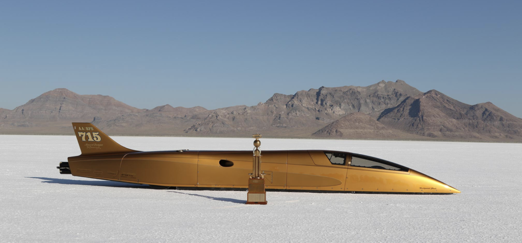
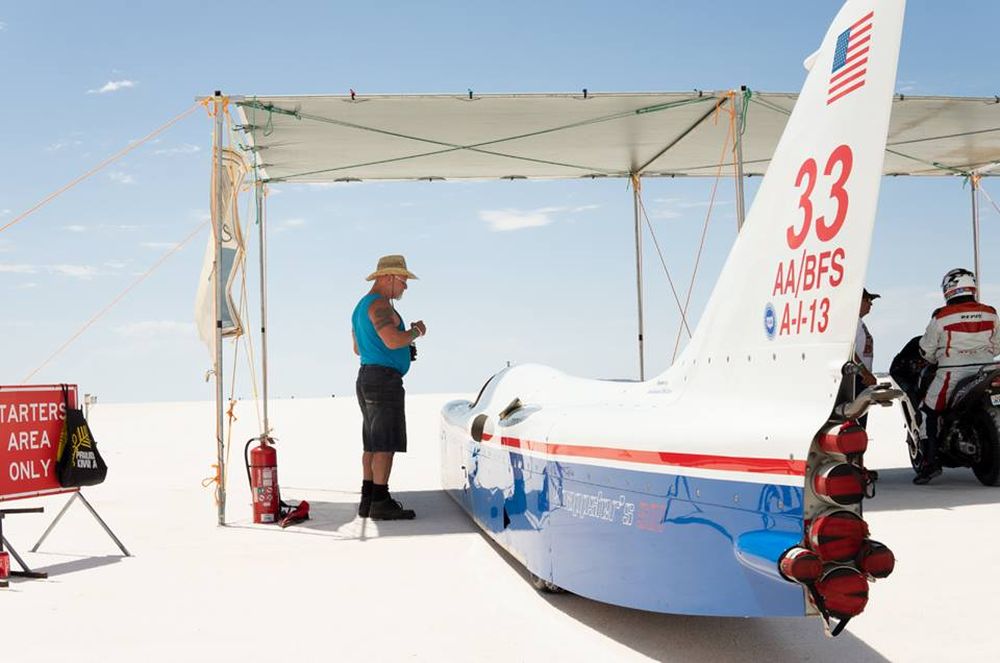
George Poteet’s Speed Demon is a blown (supercharged or turbocharged) fuel (not gasoline) streamliner (BFS) that currently holds two-way land-speed records in five out of seven of Bonneville’s BFS classes:  A, B, C, D and F.  The two remaining classes are AA/BFS and E/BFS.  The team’s goals for 2019 were to achieve records in these remaining classes and to raise its fastest two-way speed record to over 480 mph (772 kph).  The teams current record, set in 2013, stands 437.183 mph (703.578).  You can read more about these plans in the following Motor Tend article: https://www.hotrod.com/articles/pottet-speed-demon-aims-480-mph-bonneville/

To compete in several different classes, Speed Demon is designed to accommodate several different displacement engines that have been configured to fit inside the car’s svelte fuselage. At Speed Week 2019, the team had four different Duttweiler engines to challenge BFS records in Classes A, AA, C and E.

  • A 443 cubic inch twin-turbo LS engine for class A/BFS rated at around 2,870 hp with 40 pounds of boost.  You can read a 30 July 2019 article on a 441 CID version of this engine here:  https://www.msn.com/en-us/autos/enthusiasts/ken-duttweilers-2625hp-ls-bonneville-engine/ar-AAF3Drj
  • A “big block” 555 cubic inch Chevy engine for class AA/BFS, rated at around 3,200 hp at 8,000 rpm and 34 pounds of boost.
  • An intermediate size 368 cubic inch Chevy engine for class C/BFS.
  • A “small block,” 256 cubic inch Chevy engine for class E/BFS:  dyno tested to 2,632 hp at 9,640 rpm and 51 pounds of boost.

Here’s a photo of the Class A Duttweiler 443 CID LS Bonneville engine configured for Speed Demon.

Source:  https://www.hotrod.com/articles/ken-duttweilers-2625hp-ls-bonneville-engine/#007-ken-duttweiler-bonneville-ls-engine-441-ci-2625-hp
Speed Demon, 13 August 2019.  Source:  Gregg Adams photo via http://www.scta-bni.org/2019-sw-race-results.html

Speed Demon was the only car that made runs over 300 mph (483 kph) during Speed Week 2019.  On the “long” course, which was shortened to two miles because of poor salt conditions, Speed Demon achieved the following speeds:

  • 13 Aug 2019:  300.648 mph (483.846 kph) and 332.815 mph (535.614 kph) with the E “small block” engine
  • 15 Aug 2019:  369.533 mph (594.706 kph) with the AA “big block” engine

None of these runs broke an existing class speed record.  However, Speed Demon and George Poteet were honored with the Hot Rod Magazine trophy for fastest run during Speed Week 2019.

Speed Demon and 2019 trophy.  
Source:  https://www.hotrod.com/articles/george-poteets-speed-demon-tops-2019-bonneville-speed-week/

Salt Shark

Tom Flattery’s Salt Shark, a Class B blown gas (gasoline) streamliner (B/BGS), made its first appearance at Bonneville Speed Week 2019.  The Salt Shark is powered by a twin-turbo, 427 cubic inch, fuel injected LSX engine from Golen Engine Service in New Hampshire. Salt Shark reached a maximum speed of 290.568 mph (467.624 kph) on 15 August 2019, making it the second fastest car at Speed Week 2019 after Speed Demon.  You’ll find more information on the Salt Shark Facebook page here: https://www.facebook.com/Bonneville-Salt-Shark-226594851348688/

Salt Shark, August 2019.  Source, all three photos:  http://justacarguy.blogspot.com/2019/08/bonneville-speed-week-home-of.html

Target 550

The Treit and Davenport Target 550 is a Class AA blown fuel streamliner (AA/BFS).  At Bonneville Speed Week 2019, new driver Valerie Thompson took the car to a maximum speed of 270.762 mph (435.749 kph) on 15 August 2019.  Rough salt conditions prevented a return run.  

At the Utah Salt Flats Racing Association’s (USFRA) World of Speed event in October 2019, rough salt conditions persisted.  The team reported, “On its first run, the car was bouncing up and down and bottoming almost from the start line. Valerie clocked at 291 mph (468 kph), but the car went airborne due to the rough course.  Parts broke, damaging both engines.  The drag chutes deployed properly and the car came to a safe stop.  Thankfully no one was hurt.”

In January 2020, the Treit and Davenport team plans to ship Target 550 to Australia.  With Valerie Thompson driving, the team will challenge the world speed record for its class in March 2020 during Speed Week at Australia’s Lake Gairdner.

Target 550.  Source: http://target550.com

You’ll find more information on the team’s website here: https://www.target550.com

3. Utah Salt Flats Racing Association (USFRA) World of Speed 2019: 16 – 16 September 2019

Like Bonneville Speed Week 2019, the USFRA World of Speed 2019 was affected by wet salt conditions.  Results are posted on the USFRA website here:  https://saltflats.com

Only three cars reached speeds greater than 300 mph (483 kph) on runs during World of Speed 2019.  One of them, the Carbinite LSR car, the Carbiliner, was destroyed in a high-speed crash and the driver was seriously injured.

Let’s take a look at the three fastest LSR cars at this meet.

Carbinite LSR – Carbiliner

The Carbiliner is a Class AA blown fuel streamliner (AA/BFS).  In 2018, it was one of five LSR vehicles to exceed 400 mph (644 kph) during Bonneville Speed Week, making runs of 406.750 mph (654.601 kph) and 413.542 mph (665.531 kph).

The Carbiliner.  Source:  https://www.facebook.com/CarbiniteLSR/
Rob Freyvogel & the Carbiliner.  
Source: Sue Freyvogel via the Desert News

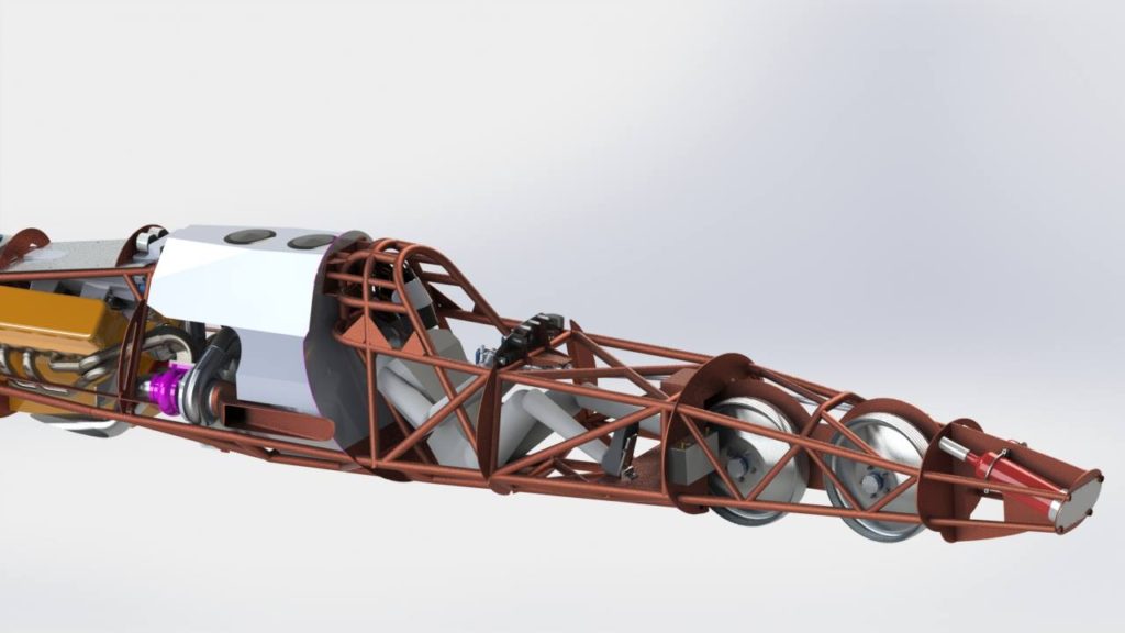
At World of Speed 2019, the Carbiliner, driven by Rob Freyvogel, crashed during a high-speed run on 15 September 2019.  The car had been measured at an average speed of 392 mph (631 kph) and was still accelerating heading into the final mile of the long course when the crash occurred.  While the rugged structure of the cockpit provided some protection, Rob Freyvogel was seriously injured.

The Carbiliner’s rugged cockpit structure.  
Source:  https://www.facebook.com/CarbiniteLSR/

You can follow Rob Freyvogel’s progress toward recovery on the Carbinite LSR Facebook page here: https://www.facebook.com/CarbiniteLSR/

A GoFundMe donation page has been set up for the family at the following link: https://www.gofundme.com/f/help-the-freyvogels

Strasburg Lakester

The Strasburg family’s LSR car is a Class C blown fuel lakester (C/BFL).  With almost perfect salt conditions at Bonneville in 2018, the Strasburg family set a new world land speed record for a lakester (an open-wheeled car) with an average speed of 373 mph (600 kph).

At World of Speed 2019, this lakester, driven by Anita Strasburg, exceeded 300 mph (483 kph) on several runs.  On the best run, Anita Strasburg recorded 347.484 mph (559.221 kph) in the last (3rd) mile with an exit speed of 350.493 mph (564.064 kph).

The Strasburg family and the fastest open-wheeled car in the world. Source: Will McKnight via https://www.lehifreepress.com/2018/08/30/

Beamco Streamliner

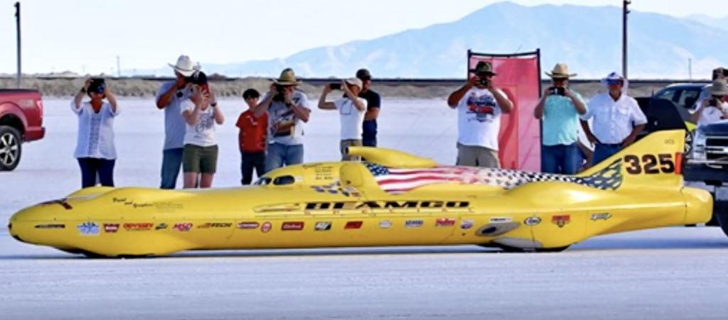
The Beamco is a Class D unblown gas streamliner (D/GS) owned by Team Vesco and driven by Bob Blakely.

The Beamco streamliner.
Screenshot from Real Tuners video at USFRA 15 September 2019

In the following video, you can take a ride aboard the Beamco streamliner as Bob Blakely raised the D/GS 2-way average speed record to 312.664 mph (503.184 kph) during the World of Speed 2019 in rough course conditions.  

Blakely also became a new 300 mph Club member.

4. Bonneville World Finals 2019

On 28 September 2019, Bill Lattin, SCTA President, reported: “Unfortunately Mother Nature is at again. We were able to drag a good course and now there is standing water on it. Due to the weather forecast coming we have decided to cancel World Finals.”

The very wet Bonneville salt flats in late September 2019.  
Source: SCTA via https://www.facebook.com/Bonneville-Racing-News-130262594200423/

5. Bloodhound LSR

After being rescued from insolvency in December 2018 by Ian Warhurst, a new company called Grafton LSR Ltd. was formed in March 2019 to be the car’s legal owner.  The team was renamed “Bloodhound LSR” and the team headquarters were moved to the UK Land Speed Record Center in Berkeley, Gloucestershire, UK.  The Bloodhound LSR website is here:  https://www.bloodhoundlsr.com

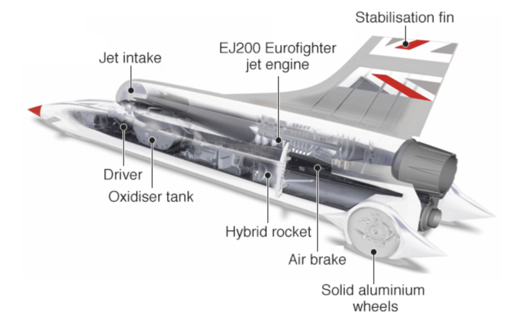
The configuration of the jet + rocket-propelled Bloodhound LSR is shown in the following diagram.

Source:  Bloodhound LSR

The team’s goal for 2019 was to conduct high-speed testing of the Bloodhound LSR at the intended land speed record venue, the Hakskeen Pan in South Africa.  The Bloodhound LSR team states that high-speed testing is “needed to allow the team to test many aspects of the car and all operational procedures in advance of the world land speed record runs, currently planned for late 2020.”Hakskeen Pan is a very flat dry lake bed with the world’s largest “unworked” saltpan.  A test track measuring 20 km (12.4 miles) long and 1,100 meters (0.68 mile) wide has been established on the saltpan for use by Bloodhound LSR.  The layout of the test track on Hakskeen Pan is show in the following diagram.  For more information on this test track, see my 8 September 2015 post, “Just How Flat is Hakskeen Pan?” here:  https://lynceans.org/all-posts/just-how-flat-is-hakskeen-pan/

Source:  BBC, https://www.bbc.com/news/science-environment-50438614

For the high-speed test phase, the Bloodhound LSR was propelled only by its EJ200 jet engine, which is rated at 90 kN (20,230 pounds) of thrust.  This engine is based on Rolls-Royce gas turbine engine technology and is built by the EuroJet Turbo GmbH consortium.  The Nammo hybrid rocket engine was not installed for the 2019 high-speed tests.

Completed Bloodhound LSR unveiled at Hakskeen Pan.
Source, both photos:  Bloodhound LSR

Test runs began on 27 October 2019, with Andy Green driving the Bloodhound LSR.  Information on all of the test runs, and selected videos, are available on the Bloodhound LSR website, under the “News” tab.  Here’s the direct link: https://www.bloodhoundlsr.com/category/bloodhound-lsr-news/

High-speed testing was completed on 17 November 2019 with a 628 mph (1,010 kph) run.  The team was pleased to report, “Mission accomplished.” You can watch a short video of this final high-speed test run here.

BBC reported, “The car’s costs are currently being underwritten by wealthy Yorkshire businessman Ian Warhurst. He says the next phase of the project will have to be funded by others, most likely corporate sponsors….. ‘With the high-speed testing phase concluded, we will now move our focus to identifying new sponsors and the investment needed to bring Bloodhound back out to Hakskeen Pan in the next 12 to 18 months’ time.’”

Development continues on the hybrid rocket engine that will be added to the Bloodhound LSR for the next set of high-speed runs at Hakskeen Pan.

You’ll find my previous posts on the Bloodhound LSR team and car here:

6. 29th Annual Speed Week at Lake Gairdner, Australia 

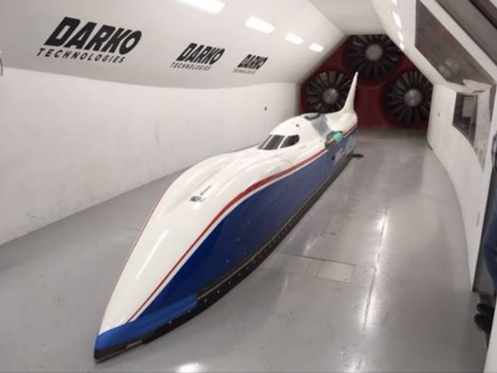
Speed Week at Lake Gairdner was held from 4 to 8 March 2019 in hot, dry weather with fair salt conditions. There was only one run over 300 mph (483 kph) at this meet. Jim Knapp’s #1584, the Knappsters Streamliner, which is a Class AA blown fuel streamliner (AA/BFS), made the top speed run of the meet at 309.438 mph (497.994 kph). 

Jim Knapp’s streamliner in the Darko wind tunnel in 2017. 
 Source: Darko Technologies via  https://www.facebook.com/CookLSS/
At Annual Speed Week 2019. Source: Photo by the 
Rodders Project via http://www.dlra.org.au/2019.htm
At Annual Speed Week 2019. Source:  Photo by 
Walt Radobike via http://www.dlra.org.au/2019.htm

The record for the top speed run at the Annual Speed Week at Lake Gairdner was set in 2018 by Les Davenport driving the Treit and Davenport Target 550, another AA/BFS, at 345.125 mph (555.425 kph).  Track conditions and weather were excellent in 2018.  The Treit and Davenport team is planning to be back in 2020.

You’ll find a summary of the 29th Annual Speed Week results here: http://www.dlra.org.au/2019.htm

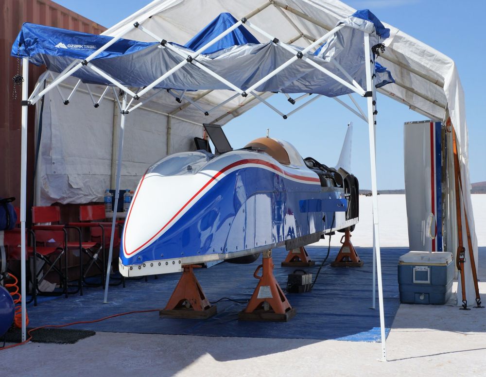
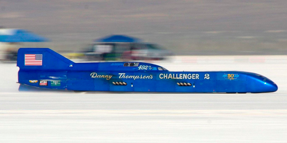
7. The world’s fastest piston-powered car, Challenger 2, is for sale

Challenger 2 is a Class AA unblown fuel streamliner (AA/FS).  Danny Thompson’s record-setting 448.757 mph (722.204 kph) average runs in Challenger 2 during Bonneville Speed Week 2018 set a new official world land speed record for piston-powered cars.  

In November 2019, Mecum Auctions announced that this famous streamliner will come up for auction at Mecum’s Kissimmee, Florida event in January 2020. No starting price has been announced.  In case you’re interested, you’ll find Mecum’s listing for the Challenger 2 here: https://www.mecum.com/lots/FL0120-397299/1968-challenger-2-streamliner/

Challenger 2 at Bonneville Speed Week 2018.  Source:  Mecum Auctions

8. 1959 Mooneyes Moonliner on display at Speed Week 2019

At Bonneville Speed Week 2019, the beautiful 1959 Mooneyes Moonliner, built by Jocko Johnson for Dean Moon, was on display.  This streamliner originally was powered by an Allison V-12 aircraft engine; later replaced by a fuel-injected, big-block Chevrolet engine.  You can follow the Moonliner on Facebook here:  https://www.facebook.com/Mooneyes/

Mooneyes Moonliner on its transporter at Bonneville Speed Week 2019.
Source:  Brandan Gillogly photo via https://www.hagerty.com/
Mooneyes Moonliner on its transporter at Bonneville Speed Week 2019.  
Source: https://gtspirit.com/2019/08/14/photo-report-spirit-speed-bonneville-speed-week-2019/
Mooneyes Moonliner at the National Hot Rod Association (NHRA) Museum. Source:  http://www.speedhunters.com/2012/04/nhra-museumthe-legend-of-moon/
Mooneyes Moonliner.  Source: https://www.reddit.com/r/WeirdWheels/comments/ap7j9c/1959_mooneyes_moonliner_bonneville_streamliner/

The Moonliner was only run for exhibitions and car shows, and never competed at any speed trials.  Nonetheless, the Moonliner is an exotic piece of rolling automotive art that could have been an exciting Class AA unblown gas streamliner (AA/GS).

In 1974, the Moonliner, powered by the big-block Chevrolet engine, driven by Gary Gabelich, and painted red and black (Budweiser colors) was at the Bonneville salt flats for a publicity run for Budweiser.  The Moonliner is reported to have reached 285 mph (458 kph) during this event.

Mooneyes Moonliner at Bonneville.
Source: 1974 Budweiser advertisement

You’ll find many historic photos of the Moonliner at Bonneville in 1974 on the Getty Images website at the following link.  Be sure to check out the photos of the unusual exhaust system.

https://www.gettyimages.com/photos/1974-moonliner?mediatype=photography&phrase=1974%20Moonliner&sort=best

A Visit to the Berlin Wall, 30 Years After it Started Coming Down

Peter Lobner

After World War II, Berlin was divided into four sectors, each controlled by a different Allied command:  United States, Great Britain, the Soviet Union, and (at the time) the provisional French Government.  The original version of the Berlin Wall was erected by East German (German Democratic Republic, GDR) authorities on 12 – 13 August 1961, completely surrounding the US, UK and French sectors, as shown in the following map.

Berlin divided into four sectors after WW II.
Source:  https://berlinmap360.com/berlin-wall-map#.Xch93S2ZMvo

The Berlin Wall physically separated the city into two halves, East Berlin and West Berlin, for more than 28 years, and went through a series of “upgrades” to make the wall a more effective physical and psychological barrier.  

President Ronald Reagan delivered his “Berlin Wall” speech on 12 June 1987 in West Berlin near the Brandenburg Gate.  You can watch a short video with that segment of his speech here:

https://www.washingtonpost.com/video/politics/watch-reagan-asks-gorbachev-to-tear-down-this-wall/2017/06/08/337df076-4c7b-11e7-987c-42ab5745db2e_video.html

For the background leading up to that famous speech, I refer you to the article by Peter Robinson, entitled “’Tear Down This Wall’ – How Top Advisers Opposed Reagan’s Challenge to Gorbachev—But Lost,” on the National Archives website here:

https://www.archives.gov/publications/prologue/2007/summer/berlin.html

On 9 November 1989, a press conference held by East Berlin’s communist party boss, Günter Schabowski, and other East German officials to discuss new travel regulations included an announcement that East German border controls, including controls is East Berlin, were being relaxed immediately.  Statements (and mis-statements) made during that press conference led to an almost immediate flood of East Germans, including East Berliners, seeking to cross into the West.  When guards at multiple border crossings relented to the overwhelming pressure from the masses of civilians, East Berliners streamed into West Berlin.

The demolition of the Berlin Wall began informally on the night of 9 November 1989, but not officially until 13 June 1990.  Most of the wall was demolished by November 1991, with a few wall segments remaining in several parts of the city. German reunification took place on 3 October 1990.

On this 30th anniversary of the “fall” of the Berlin Wall, you’ll find details on this historic event in many other sources.  Here are a few articles you might enjoy reading from the 25thanniversary of the fall of the Berlin Wall:

I was in Berlin a few weeks ago and offer the following photo essay on some of the remaining segments of the Berlin Wall, which stand as memorials to the time when the city was divided, and as reminders to us of the harsh, controlled life under East German communist rule.  We’ll take a look at photos of the Brandenburg Gate, Checkpoint Charlie, the Wall Museum at Checkpoint Charlie (Haus am Checkpoint Charlie), the DDR Museum, the East Side Gallery and the Berlin Wall Memorial on Bernauer Strasse.  The following map of Berlin shows where these important landmarks are located.  I hope you’ll find time to visit these landmarks if you ever visit Berlin.

Source: adapted from  https://berlinmap360.com/berlin-wall-map#.Xch93S2ZMvo

The Brandenburg Gate

Brandenburg Gate was on the East Berlin side of the Berlin Wall.  In 1987, it was the backdrop for President Ronald Reagan’s Berlin Wall speech.  Today, Brandenburg Gate is part of a vibrant pedestrian area at Pariser Platz.

19 November 1961.  Source:  PA Wire via Chronicle Live
Brandenburg Gate. J. Lobner photo, October 2019.

Checkpoint Charlie

Checkpoint Charlie, in the American sector, was the primary crossing point for foreigners and diplomats and the scene of occasional confrontations between U.S. and East German forces.

A 1961 standoff at Checkpoint Charlie.  Source: https://rarehistoricalphotos.com/standoff-checkpoint-charlie-1961/
Same view of Checkpoint Charlie in October 2019. P. Lobner photo.
The Checkpoint Charlie guard shack. P. Lobner photo. October 2019.
P. Lobner photo. October 2019.
View from Mauer Museum, including a sign of the times – 
McDonald’s at Checkpoint Charlie.  
P. Lobner photo. October 2019. 
KFC is right across the street.  P. Lobner photo. October 2019.

Mauer Museum (Wall Museum), Haus am Checkpoint Charlie

P. Lobner photo. October 2019.

The Mauer Museum (Haus am Checkpoint Charlie) offers an extensive permanent exhibition on the history of the Berlin Wall and on the international fight for human rights. This isn’t a museum you can go through quickly.  Large storyboards throughout the museum provide comprehensive and engaging narrative and photographic details on events and people associated with the Berlin Wall.  There are many artifacts used by people in their attempts to escape from East Berlin and many period videos of news events related to the wall.  There is a significant display on President Ronald Reagan’s 1987 Berlin Wall speech. 

You’ll find details on this museum on their website here:

http://www.mauermuseum.de/en/start/

An East German border marker at the Haus am Checkpoint Charlie.  
P. Lobner photo. October 2019.
Berlin Wall-era signage.  P. Lobner photo. October 2019.
A smuggler’s car.  
P. Lobner photo. October 2019.  
How to smuggle a person in a hi-fi speaker.
P. Lobner photo. October 2019.
More Berlin Wall-era signage.  P. Lobner photo. October 2019.  
Fragments of the Berlin Wall.  P. Lobner photo. October 2019. 

DDR Museum

The DDR Museum is an interactive museum that seeks to provide visitors with an  immersive experience of everyday life behind the Berlin Wall, in the former East Berlin.  The permanent exhibition is divided into three themed areas: Public Life, State and Ideology, and Life in a Tower Block.

The museum is located near Berlin’s city center, not far from the Alexanderplatz, across the Spree River from the Berlin Cathedral and Museum Island.

DDR Museum entrance on the Spree River.  
P. Lobner photo. October 2019. 

Life in a tower block (a Russian-style high-rise apartment building) is portrayed in a reconstruction of a surprisingly large five-room flat. Original artifacts and other objects in the apartment convey the image that East Berliners had a modest standard of living, probably well below that of their counterparts in West Berlin. The omnipresent and oppressive surveillance by the Ministry for State Security is addressed in considerable detail.

Take a simulated ride in an original Trabant P601.
P. Lobner photo. October 2019

A visit to this museum may give you a different perspective on your own life in a democratic country.  For more information, visit the DDR Museum website here:  https://www.ddr-museum.de/de

East Side Gallery

The longest preserved piece of the Berlin Wall, which stands between Ostbahnhof (East train station) and Oberbaumbrücke, is known worldwide as the East Side Gallery. After the Wall fell, 118 artists from 21 countries appropriated 1.3 kilometers of the former border wall and created the longest open-air art gallery in the world.  The city of Berlin added the East Side Gallery to its monument register in November 1991, preventing demolition and preserving the gallery from further decay. In 2009 the entire East Side Gallery was restored, with the original artists personally repainting their own artworks.  You’ll find details on the East Side Gallery at the following links:

https://www.eastsidegalleryberlin.de/en/

and

https://www.berlin.de/mauer/en/sites/traces-of-the-wall/the-east-side-gallery-a-section-of-the-inner-wall-painted-in-1990-333593.en.php

Because of its great size and its location along a busy surface street, it’s hard to get a distant view the East Side Gallery without being interrupted by an almost constant flow of traffic along Holzmarktstrasse.  It’s quite an experience to walk along the wall and consider as many of the artworks as your time permits.

P. Lobner photo. October 2019.
Dmitri Vrubel’s “My God, Help Me to Survive This Deadly Love,” captures a fraternal kiss between Russian Premier Leonid Brezhnev & East German party leader Erich Honecker.  J. Lobner photo, October 2019.  
J. Lobner photo, October 2019.
Theodor Tezhik’s “The Big Kremlin’s Wind.” 
P. Lobner photo. October 2019.
J. Lobner photo, October 2019
P. Lobner photo. October 2019.
J. Lobner photo, October 2019.  
P. Lobner photo. October 2019.

Berlin Wall Memorial on Bernauer Strasse

The Berlin Wall Memorial is Berlin’s central memorial site recalling German division.  This 1.4 kilometer section of the Berlin Wall is preserved in its full depth, allowing visitors to see the various elements of the border strip, including the “no-man’s-land,” as it looked at the end of the 1980s.  

You’ll find details on the Berlin War Memorial here:

https://www.berlin.de/mauer/en/sites/commemorative-sites/berlin-wall-memorial/

and here:

https://www.berliner-mauer-gedenkstaette.de/en/

Map of the Berlin Wall Memorial on Bernauer Strasse.  
Source: adapted from https://www.berliner-mauer-gedenkstaette.de/en/
Visitors Center at the corner of Bernauer Strasse and Gartenstrasse. 
P. Lobner photo. October 2019
The border wall (left) and the former no-man’s-land (grass area) 
to the right, at the corner of Bernauer Strasse and Gartenstrasse.
J. Lobner photo. October 2019.
Information placards in the Windows of Remembrance part of the Memorial.
P. Lobner photo. October 2019
A segment of the wall on the former East German side of the 
no-man’s land (the hinterland wall).  P. Lobner photo.  October 2019
Original border wall segments removed from their original positions, 
on display in the Windows of Remembrance part of the Memorial.  
P. Lobner photo. October 2019.
Photo memorial to persons killed while attempting to escape from 
East Berlin. A segment of the border wall along Bernauer Strasse
is in the background.  P. Lobner photo.  October 2019.
A missing section of the wall is marked by rebar.  The building has 
a famous photo of an East German border guard defecting on
 Bernauer Strasse in 1961. J. Lobner photo. October 2019.
This photo shows East Berlin border guard Conrad Schumann leaping across a barbed wire barrier at the corner of Bernauer Strasse and Ruppiner Strasse on 15 August 1961, while the Berlin Wall was being built. Source: https://rarehistoricalphotos.com/conrad-schumann-defects-west-berlin-1961/
Document Center with elevated viewing platform at the corner of  Bernauer Strasse and Ackerstrasse. Source:
https://www.berliner-mauer-gedenkstaette.de/en/
From the viewing platform at the Document Center, you can see this reconstruction of a complete wall segment with guard tower & no-man’s land between the border wall (foreground) and the inner wall (hinterland wall) on the former East Berlin side (background, behind guard tower).  P. Lobner photo. October 2019.
P. Lobner photo. October 2019
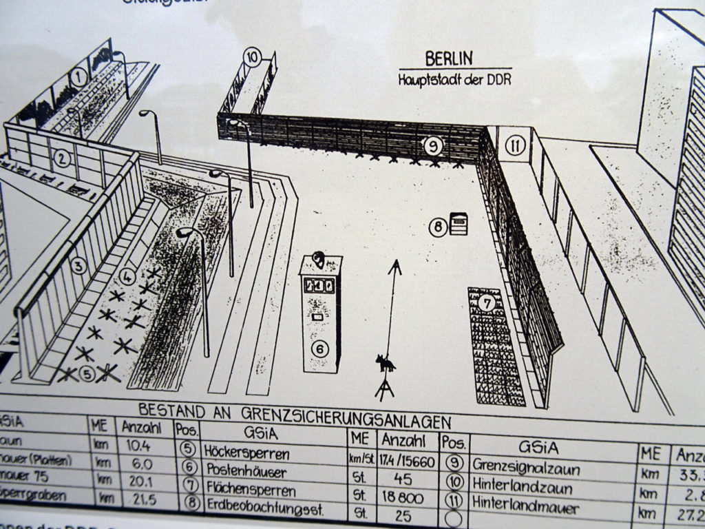
Anatomy of the Berlin Wall.  J. Lobner photo. October 2019.

U.S. Embassy near the Brandenburg Gate

In early November 2019, a bronze statue, commissioned by the Ronald Reagan Presidential Foundation, was erected on the terrace of the U.S. embassy in Berlin, overlooking the Brandenburg Gate, to memorialize President Reagan’s 1987 “Tear down this wall” speech on the 30th anniversary of the fall of the Berlin Wall.  The statue was erected at the U.S. embassy after Berlin authorities refused to allow the statue to be erected on public land.  It’s hard for me to understand how Berlin authorities could take that position.  Perhaps they need to visit the several Berlin Wall landmarks described in this post to refresh their memories on the important roles the WW II allies (U.S., UK and France) played in ensuring the freedom and safety of West Berliners for almost 45 years prior to the fall of the Wall (1989), German reunification (1990) and the collapse of the Soviet Union (1991).

U.S. embassy in Berlin.  Source:  Jörg Zägel via Wikipedia
President Ronald Reagan bronze statue on the terrace of the U.S. embassy in Berlin.  Source:  Richard Grenell via Twitter, #BerlinWall30

Top 15 Largest U.S. Companies by Revenue (1954-2018)

Peter Lobner

RankingTheWorld has created another fascinating timeline video, this one ranking the top 15 companies in the United States by revenue from 1954 to 2018. RTW explains that “the data is taken from the annual Fortune 500 list.  Fortune includes in its list all public and private companies that file financial statements with the government, and are incorporated and operate in the U.S.”  You’ll find their video here:

Within each calendar year, you’ll see quite a bit of volatility in the relative positioning within the top 15 companies, often with some companies falling below the top 15 threshold and new firms arriving to take their places.  

Through the 64 years of data, the changing complexion of U.S. industry is evident:

  • Decline in big manufacturing, with GM dropping from #3 to #13, Ford dropping from #4 to #12, and the loss of US Steel, General Electric, Bethlehem Steel and DuPont from the top 15 list.
  • Loss of food companies from the top 15 by the 1970s:  Armour and Swift & Company
  • Rapid rise of technology firms that weren’t even among the top 15 in 2010:  Apple, Amazon & Alphabet (Google’s parent).
  • Rapid rise in healthcare related service providers since 2010:  UnitedHealth Group, McKesson, CVS & AmeriSource Bergen.
  • Rise of big retailers since 2000:  Walmart & Costco
  • Persistence of some petrochemical companies:  Exxon Mobile (#2 in 1954 and in 2018) & Chevron

Following are screenshots from the RTW video that show an instant in the starting and ending years (1954 & 2018) and at the start of each decade in between. 

I think you’ll enjoy RTW’s five-minute video.  The detailed action happens quickly, so remember that you can use the YouTube Settings control to adjust playback speed.

Thanks to Lyncean member Mike Spaeth for letting me know about this RTW timeline video.  

You can watch all of RTW’s videos on their YouTube channel here: https://www.youtube.com/channel/UCFRoQ_PH8Ho5bUQb443PPqw

Celebrate the 50th Anniversary of the Birth of What Would Become the Modern Internet

Peter Lobner

On 29 October 1969, the first host-to-host connection (remote login) between two computers, one at UCLA in Los Angeles and the other at Stanford Research Institute (SRI) in the San Francisco Bay Area, was made over the first deployed general-purpose computer network.  This milestone, which occurred on a project funded by the Advanced Projects Research Agency (ARPA), was the first step toward the ARPANET, and later, what we all know today as the Internet. Remarkably, a UCLA logbook recording this event has been preserved.

One of the logbook pages that documented the first “internet” connection
made on the ARPANET on 29 October 1969 between UCLA and SRI.  
Source: UCLA Special Collections

For a detailed description of this event, see the article by Matt Novak, “Here’s the Internet’s ‘Birth Certificate’ from 50 Years Ago Today,” on the Gizmodo website at the following link:

https://paleofuture.gizmodo.com/heres-the-internets-birth-certificate-from-50-years-ago-1839436583

A Third Source of Gravitational Waves Appears to Have Been Detected

Peter Lobner

The US Laser Interferometer Gravitational-Wave Observatory (LIGO) began its third “observing run,” O3, on 1 April 2019 after a series of upgrades were completed on both LIGO instruments (in Hanford, Washington and Livingston, Louisiana) during an 18-month shutdown period after the second observing run, O2, ended on 25 August 2017.  The European Gravitational Observatory’s (EGO) Virgo instrument also joined O3.  Since its last observing run, which coincided with part of LIGO O2, Virgo also received a series of upgrades that have almost doubled its sensitivity.  O3 is scheduled to last for one calendar year.  Check out the details of these gravitational wave instruments and O3 at the following websites:

On 12 August, the LIGO / Virgo team reported:

“By July 31st, 2019, LIGO had sent out 25 alerts to possible detections, three have since been retracted, leaving us with 22 ‘candidate’ gravitational wave events. We call them “candidates” because we still need time to vet all of them. If all candidates are verified, then the number of detections made by LIGO in just the first third of O3 will double the number of detections made in its first two runs combined……So far, no electromagnetic counterparts related to our public alerts have been observed, but all candidates are being actively analyzed by LSC/Virgo science teams.”

As of July 31, 2019 LIGO/Virgo had seen:

  • 18 binary black hole merger candidates
  • 4 binary neutron star merger candidates

The LIGO-Virgo Collaboration has created the Gravitational Wave Candidate Event Database (GraceDB), which members of the public can access to track observations made during O3 here: 

https://gracedb.ligo.org/superevents/public/O3/

On 14 August 2019, the LIGO and Virgo instruments detected a gravitational wave event that appears to have come from a previously undetected source: the collision of a black hole and a neutron star.  This event, tentatively identified as S190814bv, is estimated to have occurred about 900 million light-years away.   Data from the three detectors enabled scientists to locate the source of these gravitational waves to a 23 square degree region of the sky, which would be about seven times the diameter of the Moon as seen from Earth.  While the gravitational wave signal was characterized as “remarkably strong,” so far, there have been no “multi-messenger” detections in the electromagnetic spectrum to help further refine the location and the nature of the event.

You’ll find a description of a black hole collision with a neutron star on the Simulating eXtreme Spacetimes (SXS) website at the following link:

https://www.black-holes.org/the-science-compact-objects/compact-objects/black-holes-and-neutron-stars

Here, SXS offers the following sequence of events for this exotic collision. 

Neutron star beginning to disrupt. The tidal forces of the black hole squeeze the star like a tube of toothpaste. The distance between the neutron star and the black hole is about 50 km, and they are orbiting hundreds of times per second. Source: SXS
Ejected tail flinging off into space. This matter will eventually contribute rare heavy elements to the interstellar medium. Source: SXS
Accretion disk swirling around the black hole. The accretion disk survives outside the black hole for less than a second. But this is enough time to release an enormous amount of energy in the form of neutrinos. It spans a little more than a hundred km from side to side.
Source: SXS

For more information, check the LIGO and Virgo websites for their news updates.

Modern Airships – Part 1

Peter Lobner, updated 8 January 2025 (post-Rev. 6)

1. Introduction

Modern Airships is a three-part document that contains an overview of modern airship and aerostat technology in Part 1 and links in Parts 1, 2 and 3 to more than 285 individual articles on historic and advanced airship designs.  This is Part 1.  Here are the links to the other two parts:

To help you navigate the large volume of material in these three documents, please refer to following indexes. The first index simply lists the article titles in alphabetic order within each Part.

Parts 1 & 2 address similar types of airships and unpowered aerostats. The following airship type index enables you to see all of the airships and aerostats addressed in Parts 1 & 2, grouped by type, with direct links to the relevant articles.

The airships described in Part 3 are relatively exotic concepts in comparison to the more utilitarian and heavy-lift airships that dominate Parts 1 and 2. As shown in the following index, the airships in Part 3 are organized by function rather than airship type, which sometimes is difficult to determine with the information available.

Modern Airships – Part 1 begins with an overview of modern airship and aerostat technology, continues with a graphic table that identifies the airships addressed in this part, and concludes by providing links to more than 100 individual articles on these airships. A downloadable pdf copy of Part 1 is available here:

If you have any comments or wish to identify errors in this document, please send me an e-mail to:  [email protected].

I hope you’ll find the Modern Airships series to be informative, useful, and different from any other single document on this subject.

Best regards,

Peter Lobner

8 January 2025

Record of revisions to Part 1

  • Original Modern Airships post, 26 August 2016: addressed 14 airships in a single post.
  • Expanded the Modern Airships post and split it into three parts, 18 August 2019: Part 1 included 22 linked articles.
  • Part 1, Revision 1, 21 December 2020: Added 15 new articles, split the existing Aeros article into two articles and updated all of the original articles. Part 1 now had 38 articles.
  • Part 1, Revision 2, 3 April 2021: Updated the main text and 10 existing articles, and expanded and reorganized the graphic tables. Part 1 still had 38 articles
  • Part 1, Revision 3, 26 August 2021: Added 34 new articles, split the existing Helistat article into five articles and the Aereon article into two articles, and expanded and reorganized the graphic tables. Also updated 23 existing articles. Part 1 now had 77 articles.
  • Part 1, Revision  4, 12 February 2022: Added 12 new articles, split the existing Airlander article into two updated articles (prototype, production), moved Halo to Part 3, expanded the graphic tables and updated 17 additional existing articles.  A detailed summary of changes incorporated in Part 1 Rev 4 is listed here. Part 1 now had 89 articles.
  • Part 1, Revision  5, 10 March 2022: Added 2 new articles, split rigid & semi-rigid airships in the graphic tables, and updated 58 existing articles. With this revision, all Part 1 linked articles have been updated in February or March 2022. A detailed summary of changes incorporated in Part 1 Rev 5 is listed here. Part 1 now has 91 articles.
  • Part 1, Revision 6, 17 March 2024: This revision includes a major reorganization of Parts 1 & 2 to better aggregate airships and unpowered aerostats by type, with a corresponding reorganization of the graphic tables. Over the past two years, 15 new articles were added to Part 1 and 28 articles were updated. In the final changes for Rev. 6, several articles were moved between Parts 1 & 2. A detailed summary of changes incorporated in Part 1 Rev 6 is listed here. Part 1 now has 107 articles.

Part 1, changes since Rev. 6 (17 March 2024)

New articles:

  • Platforms Wireless International Corp. – ARC System – 2 December 2024
  • Altaeros Energies – SuperTower tethered aerostats – 8 January 2025

Updated articles:

  • LTA Research and Exploration – 8 July 2024
  • AT2 Aerospace – 17 September 2024
  • Lockheed Martin – P-791 – 30 September 2024
  • Lockheed Martin – Sky Tug and LMH-1 – 30 September 2024
  • Hybrid Air Vehicles (HAV) / Northrop Grumman – HAV-3 and HAV-304 (LEMV) – 2 October 2024
  • Hybrid Air Vehicles (HAV) – Airlander 10 prototype – 2 October 2024
  • Walden Aerospace / LTAS / LTASI – Lenticular, toroidal, variable buoyancy airships – 18 October 2024, 5 November 2024
  • SAIC – Skybus 1500 – 6 November 2024
  • Airship Industries Ltd. – 6 November 2024

2.  Well-established benefits and opportunities, but a risk-averse market

For several decades, there has been significant interest in the use of modern lighter-than-air craft and hybrid airships in a variety of military, commercial and other roles, including:

  • Heavy cargo carriers operating point-to-point between manufacturer and end-user, eliminating inter-modal load transfers enroute
  • Heavy cargo carriers serving remote and/or unimproved sites not adequately served by other modes of transportation
  • Disaster relief, particularly in areas not easily accessible by other means
  • Persistent optionally-manned surveillance platforms for military intelligence, surveillance & reconnaissance (ISR), maritime surveillance, border patrol, search and rescue
  • Passenger airships
  • Commercial flying cruise liner / flying hotel
  • Airship yacht
  • Personal airship
  • Drone carrier
  • High altitude regional communications node

One of the very significant factors driving interest in modern airships is that they offer the potential to link isolated regions with the rest of the world while doing so in a way that should have lower environmental impacts than other transportation alternatives for those regions. This target market for airships exists in more than two-thirds of the world’s land area where more than half the world’s population live without direct access to paved roads and reliable ground transportation.

This matter is described well in a 21 February 2016 article by Jeanne Marie Laskas, “Helium Dreams – A new generation of airships is born,” which is posted on The New Yorker website at the following link: https://www.newyorker.com/magazine/2016/02/29/a-new-generation-of-airships-is-born

In spite of the significant interest and the development of many promising airship designs, an actual worldwide airship cargo and passenger transportation industry has been very slow in developing.  To give you an example of how slow:

  • As of November 2023, other than a modest number of commercially certified blimps used largely as advertising platforms, the Zeppelin NT 07 is the only advanced airship that has been certified and is flying regularly in commercial passenger service. 
  • At the March 2019 Aviation Innovations Conference – Cargo Airships in Toronto, Canada, Solar Ship CEO Jay Godsall proposed an industry-wide challenge to actually demonstrate by July 2021 airships that can move a 3 metric ton (6,614 lb) standard 20 foot intermodal container configured as a mobile medical lab 300 km (186 mi) to a remote location. Godsall noted that this capability would be of great value if it did exist, for example, in support of relief efforts in Africa and other regions of the world.

So in spite of the airship industry having developed many designs capable of transporting 10’s to 100’s of tons of cargo thousands of miles, today there is not a single airship than can transport a 3 metric ton (6,614 lb) payload 300 km (186 mi).

Why has the airship industry been so slow to develop?  The bottom line has been a persistent lack of funding.  With many manufacturers having invested in developing advanced designs in varying levels of detail, the first to secure adequate funding will be able to take the next steps to build and certify a manufacturing facility, build and flight test a full-scale prototype airship, complete the airship type certification process, and start offering a certified airship for sale.

There are some significant roadblocks in the way:

  • No full-scale prototypes are flying:  Many airship firms currently have little more than slide presentations to show to potential investors and customers.  There are few sub-scale airship demonstrators, but no full-scale prototypes.  The airship firms are depending on potential investors and customers making a “leap of faith” that the “paper” airship actually can be delivered. However, this situation will change significantly in the next few years as several airship manufacturers (i.e., LTA Research and Exploration, Flying Whales and Hybrid Air Vehicles) finally complete their full-scale, large airship prototypes and commence flight testing.
  • Immature manufacturing capability:  While the airship industry has been good at developing many advanced designs, some claiming to exist as “construction-ready” plans, few airship firms are in the process of building an airship factory. The industrial scale-up factor for an airship firm to go from the design and engineering facilities existing today to the facilities needed for series production of full-scale airships is huge.  LTA Research and Exploration is one of the few firms with access to modernized large airship hangars (the former Goodyear Airdock in Akron OH and the former Navy airship hangars at Moffett Field, CA) for use as manufacturing facilities. In 2016, Russian airship manufacturer Augur RosAeroSystems proposed building a new factory to manufacture up to 10 ATLANT airships per year. The funding requirement for that factory was estimated at $157 million.  The exact amount isn’t important.  No matter how you look at it, it’s a big number.  Large investments are needed for any airship firm to become a viable manufacturer.
  • Significant financial risk: The amount of funding needed by airship firms to make the next steps toward becoming a viable manufacturer exceeds the amount available from venture capitalists who are willing to accept significant risk. Private equity sources typically are risk averse.  Public sources, or public-private partnerships, have been slow to develop an interest in the airship industry. The French airship firm Flying Whales appears to be the first to have gained access to significant funding from public institutions.  
  • Significant regulatory risk: Current US, Canadian and European airship regulations were developed for non-rigid blimps and they fail to address how to certify most of the advanced airships currently under development.  This means that the first airship manufacturers seeking type certificates for advanced airships will face uphill battles as they have to deal with aviation regulatory authorities struggling to fill in the big gaps in their regulatory framework and set precedents for later applicants.  It is incumbent on the aviation regulatory authorities to get updated regulations in place in a timely manner and make the regulatory process predictable for existing and future applicants.  
  • No airship operational infrastructure:  There is nothing existing today that is intended to support the operation of new commercial airships tomorrow.  The early airship operators will need to develop operating bases, hangar facilities, maintenance facilities, airship routes, and commercial arrangements for cargo and passengers.  While many airship manufacturers boast that their designs can operate from unimproved sites without most or all of the traditional ground infrastructure required by zeppelins and blimps, the fact of the matter is that not all advanced airships will be operating from dirt fields and parked outside when not flying.  There is real infrastructure to be built, and this will require a significant investment by the airship operators.
  • Steep learning curve for potential customers:  Only the operators of the Zeppelin NT have experience in operating a modern airship today.  The process for integrating airship operations and maintenance into a customer’s business work flow has more than a few unknowns.  With the lack of modern airship operational experience, there are no testimonials or help lines to support a new customer.  They’ll have to work out the details with only limited support.  Ten years from now, the situation should be vastly improved, but for the first operators, it will be a challenge.
  • Few qualified pilots and crew:  The airship manufacturers will need to work with the aviation regulatory authorities and develop programs for training and licensing new pilots and crew.  The British airship manufacturer Varialift has stated that one of the roles of their ARH-PT prototype will be to train future pilots.  

This uncertain business climate for airships seems likely to change in the mid-to-late 2020s, when several different heavy-lift and passenger airships are expected to be certified by airworthiness authorities and ready for series production and sale to interested customers. If customers step up and place significant orders, we may be able to realize the promise of airship travel and its potential to change our world in many positive ways.

3. Status of current aviation regulations for airships

As noted previously, current aviation regulations have not kept pace with the development of modern airship technology.  In this section, we’ll take a look at the current regulations.

US Federal Aviation Administration (FAA)

In the US, the FAA’s current requirements for airships are defined in the document FAA-P-8110-2, Change 2, “Airship Design Criteria (ADC),” dated 6 February 1995, which is available here:

https://www.faa.gov/aircraft/air_cert/design_approvals/airships/airships_regs/media/aceAirshipDesignCriteria.pdf

The ADC applies to non-rigid, near-equilibrium, conventional airships with seating for nine passengers or less, excluding the pilot, and it serves as the basis for issuing the type certificate required before a particular airship type can enter commercial service in the US.  The limited scope of this current regulation is highlighted by the following definitions contained in the ADC:

  • Airship:  an engine-driven, lighter-than-air aircraft, than can be steered.
  • Non-rigid: an airship whose structural integrity and shape is maintained by the pressure of the gas contained within the envelope.
  • Near-equilibrium: an airship that is capable of achieving zero static heaviness during normal flight operations.

Supplementary guidance for non-rigid, near-equilibrium, conventional airships is provided in FAA Advisory Circular (AC) No. 21.17-1A, “Type Certification – Airships,” dated 25 September 1992, which is available here:

https://www.faa.gov/documentlibrary/media/advisory_circular/ac_21-17-1a.pdf

The FAA’s ADC and the associated AC were written for blimps, not for the range of modern airships under development today.  For example, aerostatic lift is only one component of lift in modern hybrid airships, which also depend on powered lift from engines and aerodynamic lift during forward flight.  Hybrid airships are not “lighter-than-air” and cannot achieve zero static heaviness during normal operations, yet they are an important class of airships being developed in several countries.  In addition, almost all modern airships, except blimps, have rigid or semi-rigid structures that enable them to carry heavy loads and mount powerful engines on locations other than the gondola of a non-rigid airship.

On March 12, 2012 the FAA announced that Lockheed Martin Aeronautics submitted an application for type certification for their model LMZ1M (LMH-1), which is “a manned cargo lifting hybrid airship incorporating a number of advanced features.”  The FAA assigned that application to their docket number FAA-2013-0550. 

To address the gap in airship regulations head-on, Lockheed Martin submitted to the FAA their recommended criteria document, “Hybrid Certification Criteria (HCC) for Transport Category Hybrid Airships,” which is a 206 page document developed specifically for the LMZ1M (LMH-1).  The HCC is also known as Lockheed Martin Aeronautics Company Document Number 1008D0122, Rev. C, dated 31 January 2013.  You can download the HCC document and related public docketed items on the FAA website here: 

https://www.regulations.gov/docket/FAA-2013-0550/document

In November 2015, Lockheed Martin announced that the FAA’s Seattle Aircraft Certification Office had approved the project-specific certification plan for the LMZ1M (LMH-1). At the time Lockheed Martin transitioned their hybrid airship business to AT2 Aerospace in May 2023, their hybrid airship had not yet been type certified.

Germany & Netherlands

Recognizing the absence of an adequate regulatory framework for modern airships, civil aviation authorities of Germany and Netherlands developed supplementary guidance to the European Joint Aviation Requirements (JAR-25) and the FAA’s ADC for a category of airships called “Transport Airships,” which they define as follows:

“The transport category is defined for multi-engine propeller driven airships that have a capacity of 20 or more passengers (excluding crew), or a maximum take-off mass of 15,000 kg or more, or a design lifting gas volume of 20,000 m3 or more, whichever is greater.”

These supplementary requirements are contained in the document  “Transport Airship Requirements” (TAR), dated March 2000, which you will find at the following link: https://www.faa.gov/aircraft/air_cert/design_approvals/airships/airships_regs/media/aceAirshipTARIssue1.pdf

European Union Aviation Safety Agency (EASA)

On 11 February 2021, the European Union Aviation Safety Agency (EASA) proposed a new regulatory framework for the certification of large airships.  The proposed document went through a public review and comment period before the final document was issued on 21 January 2022 as Doc. No. SC GAS, “Special Condition ‘SC GAS’ Gas Airships,” which is available here: https://www.easa.europa.eu/downloads/134946/en

EASA explained their rationale for this special condition document:

“EASA has received applications for the type certification of large Airships but has not yet published Certification Specifications (CS) for these products…… In the absence of agreed and published certification specifications for Airships by EASA…….a complete set of dedicated technical specifications in the form of a Special Condition for Gas Airships has been developed. This Special Condition addresses the unique characteristics of Airships and defines airworthiness specifications that may be used to demonstrate compliance with the essential requirements in Annex II of regulation (EU) 2018/1139 of the European Parliament and Council. That is required before the issuance of the EASA type certificate, as well as for the approval of later changes to type certificate.”

“The Special Condition is a high-level set of objective driven and performance-based requirements. It was developed in close cooperation with the industry working group. The Special Condition addresses two designs, one being a 260,000 m3 rigid equilibrium Airship for cargo operations, the other one a 45,000 m3 non-rigid hybrid Airship for up to 100 passengers. However, the authors believe the SC can be applied to all manned Airships with non-pressurized crew or passenger compartments. It will be subject to EASA Certification Team agreement whether this Special Condition can be deemed sufficient as a Certification Basis, for example unmanned designs are not sufficiently addressed by this proposal. Due to the low number of projects no categories have been established. The different safety levels applicable to specific Airship designs will be addressed through the Means of Compliance (MOC).”

The EASA is ahead of the FAA in terms of having published usable interim regulations for advanced airships.  However, both EASA and FAA regulators are lagging the development of advanced civilian airship designs that may be submitted for type certification in the next decade. The lack of mature regulations for advanced airship designs will increase the regulatory risk for the designers / manufacturers of those airships.

4. Lifting gas

In the US, Europe and Canada, the following aviation regulations only allow the use of non-flammable lifting gas:

  • FAA ADC:  “The lifting gas must be non-flammable.” (4.48)
  • TAR:  “The lifting gas must be non-flammable, non-toxic and non-irritant.” (TAR 893)
  • Canadian Air Regulations:  “Hydrogen is not an acceptable lifting gas for use in airships.” (541.7)

The EASA proposed Special Condition issued on 21 January 2022 creates an opportunity to use flammable lifting gases, subject to the following conditions: 

  • SC GAS.2355 Lifting gas system
    • Lifting gas systems required for the safe operation of the Airship must:
      • withstand all loading conditions expected in operation including emergency conditions
      • monitor and control lifting performance and degradation
    • If the lifting gas is toxic, irritant or flammable, adequate measures must be taken in design and operation to ensure the safety of the occupants and people on the ground in all envisaged ground and flight conditions including emergency conditions.
  • SC GAS.2340 Electrostatic Discharge
    • There must be appropriate electrostatic discharge means in the design of each Airship whose lift-producing medium contains a flammable gas to ensure that the effects of electrostatic discharge will not create a hazard.
  • SC GAS.2325 Fire Protection
    • The design must minimize the risk of fire initiation caused by:
      • Anticipated heat or energy dissipation or system failures or overheat that are expected to generate heat sufficient to ignite a fire;
      • Ignition of flammable fluids, gases or vapors; and
      • Fire propagating or initiating system characteristics (e.g. oxygen systems); and
      • A survivable emergency landing.

Without hydrogen, the remaining practical choices for lifting gas are  helium and hot air. A given volume of hot air can lift only about one-third as much as the same volume of helium, making helium the near-universal choice, with hot air being relegated to a few, small thermal airships and larger thermal-gas (Rozière) airships.

The current high price of helium is a factor in the renewed interest in hydrogen as a lifting gas.  It’s also a key selling point for thermal airships.  Most helium is produced as a byproduct from natural gas production, hence, helium is not “rare.” However, only a very small fraction of helium available in natural gas currently is recovered, on the order of 1.25%.  The remainder is released to the atmosphere. The helium recovery rate could be higher, but is not warranted by the current market for helium.  Helium is difficult to store.  The cost of transportation to end-users is a big fraction of the market price of helium.

Hydrogen provides 10% more lift than helium.  It can be manufactured easily at low cost and can be stored.  If needed, hydrogen can be produced with simple equipment in the field.  This could be an important capability for recovering an airship damaged and grounded in a remote region.  One airship concept described in Modern Airships – Part 3, the Aeromodeller II, is designed for using hydrogen as the lifting gas and as a clean fuel (zero greenhouse gases produced) for its propulsion engines.  A unique feature of this airship concept is an on-board system to generate more hydrogen when needed from the electrolysis of water ballast.

A technique for preventing hydrogen flammability is described in Russian patent RU2441685C2, “Gas compound used to prevent inflammation and explosion of hydrogen-air mixtures,” which was filed in 2010 and granted in 2012. This technique appears to be applicable to an airship using hydrogen as its lifting gas.  You can read the patent at the following link: https://patents.google.com/patent/RU2441685C2/en

The Canadian airship firm Buoyant Aircraft Systems International (BASI) is a proponent of using hydrogen lifting gas.  Anticipating a future opportunity to use hydrogen, they have designed their lifting gas cells to be able to operate with either helium or hydrogen.  

Additional regulatory changes will be required to permit the general use of hydrogen in aviation.  With the growing interest in the use of hydrogen fuel in aviation, it seems only a matter of time before it is approved for use as a lifting gas in commercial airships.

Even with the needed regulatory changes, the insurance industry will have to deal with the matter of insuring a hydrogen-filled airship. 

5.  Types of modern airships and aerostats

The term “aerostat” broadly includes all lighter than air vehicles that gain lift through the use of a buoyant gas. Aerostats include unpowered balloons (tethered or free-flying) and powered airships. The following types of airships are described in the Modern Airships series of documents:  

  • Conventional airships
    • Rigid airships
    • Semi-rigid airships
    • Non-rigid airships (blimps)
  • Variable buoyancy airships
    • Variable buoyancy, fixed volume airships
    • Variable buoyancy, fixed volume, variable vacuum airships
    • Variable buoyancy, variable volume airships
    • Variable buoyancy, hybrid thermal-gas (Rozière) airships
    • Variable buoyancy propulsion airships / aircraft
  • Semi-buoyant hybrid air vehicles
    • Semi-buoyant, hybrid airships
    • Semi-buoyant, airplane / airship hybrids (Dynairship, Dynalifter, Megalifter)
    • Semi-buoyant, helicopter / airship hybrids (helistats, Dynastats, rotostats)
  • Stratospheric airships / High-Altitude Platform Stations (HAPS)
  • Personal gas airships
  • Thermal (hot air) airships
  • Hybrid rocket / balloon (Rockoon) airships
  • Electro-kinetically (EK) propelled airships
  • LTA drones
  • Unpowered aerostats
    • Tethered aerostats (kite balloons)
    • Tethered manned aerostats
    • Tethered LTA wind turbines
    • Tethered heavy lift balloons
    • Hybrid tethered aerostat / free-flying powered airships
    • Free-flying high-altitude balloons 
    • Free-flying manned high-altitude balloons 

5.1  Conventional airships

Conventional airships are lighter-than-air (LTA) vehicles that operate at or near neutral buoyancy. The lifting gas (helium) generates approximately 100% of the lift at low speed, thereby permitting vertical takeoff and landing (VTOL) operations and hovering with little or no lift contribution from the propulsion / maneuvering system.  Various types of propulsors may be used for cruise flight propulsion and for low-speed maneuvering and station keeping. 

Airships of this type include rigid zeppelins, semi-rigid airships and non-rigid blimps.

  • Rigid airships: These airships have a lightweight, rigid airframe with an outer skin that defines their exterior shape. The airframe supports the gondola, engines and payload. Most have atmospheric pressure lifting gas cells located within the rigid airframe. A special case is a metal-clad rigid airship, with a metal hull that is self-supporting at atmospheric pressure, but typically operates with a slightly positive internal pressure.
  • Semi-rigid airships:  These airships have a rigid structural framework (i.e., a keel or an internal framework) that supports loads and is connected via a load distribution system to a flexible, pressure-stabilized envelope that defines the exterior shape and typically contains air ballonets.
  • Non-rigid airships (blimps): These airships have a pressure-stabilized, flexible envelope that defines the exterior shape of the airship and typically contains air ballonets. There is no keel or internal structure. Most loads are attached to the gondola and are transferred via a load distribution system to the envelope.

The LTA Research and Exploration Pathfinder 1 and the Flying Whales LCA60T are examples of conventional rigid airships.

The Zeppelin NT and the SkyLifter are examples of conventional semi-rigid airships.

The Aeros 40D Sky Dragon and the American Blimp Corporation MZ-3A (A-170G) are examples of conventional non-rigid airships (blimps).

After being loaded and ballasted before flight, conventional airships have various means to exercise in-flight control over their aerostatic buoyancy, internal pressure and trim. Buoyancy control is exercised with ballast and lifting gas. Internal pressure is controlled with air ballonets and lifting gas vents. Trim is adjusted with the air ballonets or moveable ballast.

Conventional airships with thrust vectoring propulsors have the ability to operate with some degree of net aerostatic heaviness or lightness that can be compensated for with the dynamic thrust (lift or downforce) from the adjustable propulsors.

Controlling buoyancy with ballast  

Many conventional airships require adjustable ballast (i.e., typically water or sand) that can be added or removed as needed to establish a desired net buoyancy before flight.  Load exchanges (i.e., taking on or discharging cargo or passengers) can change the overall mass of an airship and may require a corresponding ballast adjustment during or after the load exchange. 

In-flight use of fuel and other consumables can change the overall mass of an airship.  The primary combustion products of diesel fuel are water and carbon dioxide.  To reduce the loss of mass from fuel consumption, some airships use a rather complex system to recover water from the engine exhaust.  A modern diesel engine water recovery system being developed for the Aerovehicles AV-10 blimp is expected to recover 60% to 70% of the weight of the fuel burned, significantly reducing the change in airship mass during a long mission.

Some Navy blimps and other long-range airships have had a hoist system that could be used in flight to retrieve water from the ocean or any other body of water to increase the amount of on-board ballast.

If an airship becomes heavy, ballast can be dumped in flight to increase aerostatic buoyancy.

Controlling buoyancy with lifting gas  

The lifting gas inside an airship may be at atmospheric pressure (most rigid airships) or at a pressure slightly greater than atmospheric (semi-rigid and non-rigid airships).  Normally, there is no significant loss (leakage) of lifting gas to the environment.  A given mass of lifting gas will create a constant lift force, regardless of pressure or altitude, when the lifting gas is at equal pressure and temperature with the surrounding air. Therefore, a change in altitude will not change the aerostatic lift.  

However, temperature differentials between the lifting gas and the ambient air will affect the aerostatic lift produced by the lifting gas.  To exploit this behavior, some airships can control buoyancy using lifting gas heaters / coolers to manage gas temperature.  

The lifting gas heaters are important for operation in the Arctic, where a cold-soak in nighttime temperatures may result in the lifting gas temperature lagging behind daytime ambient air temperature.  This temperature differential would result in a loss of lift until lifting gas and ambient air temperatures were equal.

Conversely, operating an airship in hot regions can result in the lifting gas temperature rising above ambient air temperature (the lifting gas becomes “superheated”), thereby increasing buoyancy. To restore buoyancy in this case, some airships have coolers (i.e., helium-to-air heat exchangers) in the lifting gas cells to remove heat from the lifting gas.

As described by Boyle’s Law, pressure (P) and gas volume (V) are inversely proportional at a constant temperature according to the following relationship:  PV = K, where K is a constant.  As an airship ascends, atmospheric pressure decreases.  This means that a fixed mass of lifting gas will expand within the lifting gas cells during ascent, and will contract within the lifting gas cells during descent.  As described previously, this lifting gas expansion and contraction does not affect the magnitude of the aerostatic lift as long as the lifting gas is at equal pressure and temperature with the surrounding air.

If an airship is light and the desired buoyancy cannot be restored with lifting gas coolers, it is possible to vent some lifting gas to the atmosphere to decrease aerostatic lift. Usually there are two types of vents: a manually-operated vent controlled by the pilot and an automatically-operated safety vent designed to protect the envelope from overpressure.

Role of the ballonets

The airship hull / envelope is divided into one or more sealed lifting gas volumes and separate gas volumes called “ballonets” that contain air at ambient, or near-ambient pressure. The ballonets serve as the expansion space that is available for the lifting gas cells as the airship ascends.  

The ratio of the total envelope volume to the total ballonet volume is a measure of the expansion space for the lifting gas and is a key factor in determining the airship’s “pressure altitude.” This is the altitude at which the lifting gas cells are fully expanded, and the ballonets are empty. For example, with an envelope volume of 8,255 m3 (290,450 ft3) and a ballonet volume of 2,000 m3 (71,000 ft3), or about 24% of the envelope volume, a Zeppelin NT semi-rigid airship has a reported maximum altitude of 3,000 m (9,842 ft), with the envelope positive pressure of 5 mbar. With a smaller ballonet volume, the Zeppelin NT would have a lower maximum altitude at the specified internal pressure.

In semi-rigid and non-rigid airships with pressure-stabilized hulls, the ballonets are part of the airship’s pressure control system, which automatically maintains the envelope pressure in a desired range. Pressure control is accomplished by changing the volume of the ballonets. An air induction system draws atmospheric air and delivers it at a slight positive pressure (relative to envelope pressure) to increase ballonet volume. An air vent system will discharge air from the ballonets to the ambient atmosphere. While there is a change in mass during these ballonet operations, it is relatively small and does not significantly affect the aerostatic buoyancy of the airship.

Fore and aft ballonets can be operated individually to adjust the trim (pitch angle) of the airship. Inflating only the fore or aft ballonet, and allowing the opposite ballonet to deflate, will make the bow or stern of the airship slightly heavier and change the pitch angle of the airship without significantly affecting the overall aerostatic buoyancy.  These ballonet operating principles are shown in the following diagrams of a blimp with two ballonets, which are shown in blue.

Blimp with two ballonets (blue).  Top diagram shows airship with both ballonets full for level cruise flight at low altitude. The middle diagram shows the forward ballonet full and the aft ballonet empty, creating a slightly nose-heavy condition for descending flight. The bottom diagram shows the forward ballonet empty and the aft ballonet full, creating a slightly tail-heavy condition for ascending flight. Source:  zeppelinfan.de

5.2  Variable buoyancy airships

Variable buoyancy airships can change their net lift, or “static heaviness,” to become lighter-than-air, neutrally buoyant or heavier-than-air as the circumstances require. Basic characteristics of variable buoyancy airships include the following:

  • Variable buoyancy airships are capable of VTOL operations and hovering, usually with a full load.
  • The buoyancy control system may enable in-flight load exchanges from a hovering airship without the need for external ballast.
  • On the ground, variable buoyancy airships can make themselves heavier-than-air to facilitate load exchanges without the need for external infrastructure or ballast.
  • It is not necessary for a “light” airship to vent the lifting gas to the atmosphere.

Variable buoyancy, fixed volume airships

Variable buoyancy commonly is implemented by adjusting the density of the lifting gas or a ballast gas, and thereby changing the static heaviness of a fixed volume airship.  This also is referred to as density-controlled buoyancy (DCB). For example, a variable buoyancy / fixed volume airship can become heavier by compressing the helium lifting gas or ambient air ballast:

  • Compressing some of the helium lifting gas into smaller volume tanks aboard the airship reduces the total mass of helium available to generate aerostatic lift.
  • Compressing ambient air into pressurized tanks aboard the airship adds mass (ballast) to the airship and thus decreases the net lift.

The airship becomes lighter by venting the pressurized gas tanks:

  • Compressed helium lifting gas is vented back into the helium lifting gas cells, increasing the mass of helium available to generate aerostatic lift.
  • Compressed air is vented to the atmosphere, reducing the mass of the airship and thus increasing net lift.

The Aeros Aeroscraft Dragon Dream and the Varilift ARH-50 are examples of variable buoyancy / fixed volume airships.

Variable buoyancy, fixed volume, variable vacuum airships

Instead of using a low-density gas to generate aerostatic lift, a vacuum airship uses very low-density air (a partial vacuum) to generate lift, which can be controlled by managing the vacuum conditions inside lightweight, fixed volume structures capable of retaining the vacuum.  The key challenge is making the variable vacuum containment and associated systems light enough to generate net lift. Once that has been achieved, then the challenge will be to package that variable buoyancy / variable vacuum system into a functional airship. These challenges have been accepted by Anumá Aerospace and by engineer Ilia Toli.

Variable buoyancy, variable volume airships

Variable buoyancy also can be implemented by adjusting the total volume of the helium envelope without changing the mass of helium in the envelope. 

  • As the size of the helium envelope increases, the airship displaces more air and the buoyant force of the atmosphere acting on the airship increases. Static heaviness decreases.
  • As the size of the helium envelope decreases, the airship displaces less air and the buoyant force of the atmosphere acting on the airship decreases.  Static heaviness increases.

The concept for a variable buoyancy / variable volume airship seems to have originated in the mid-1970s with inventor Arthur Clyde Davenport and the firm Dynapods, Inc. The tri-lobe Voliris airships and the EADS Tropospheric Airship are modern examples of variable buoyancy / variable volume airships.

Variable buoyancy, hybrid thermal-gas (Rozière) airships

This buoyancy control concept was developed and applied in the 1700s in hybrid balloons designed by Jean-François Pilâtre de Rozière.  Such “Rozière” balloons have separate chambers for a non-heated lift gas (hydrogen or helium) and a heated lift gas (air).  This concept has been carried over into airships. With helium alone the airship is semi-buoyant (heavier-than-air).  Buoyancy is managed by controlling the heating and cooling of the air in a separate “thermal volume.” Examples of hybrid thermal (Rozière) airships are the British Thermo-Skyship (circa 1970s to early 1980s), Russian Thermoplane ALA-40 (circa 1980s to early 1990s), and the heavy-lift Aerosmena (AIDBA) “aeroplatform” currently being developed in Russia. All are lenticular (lens-shaped) airships.

Variable buoyancy propulsion airships / aircraft

Back in the 1860s, Dr. Solomon Andrews invented the directionally maneuverable, hydrogen-filled airship named Aereon that used variable buoyancy (VB) and airflow around the airship’s gas envelope to provide propulsion without an engine. 

VB propulsion airships / aircraft fly a repeating sinusoidal flight profile in which they gain altitude as positively buoyant hybrid airships, then decrease their buoyancy at some maximum altitude and continue to fly under the influence of gravity as a semi-buoyant glider. After gradually losing altitude during a long glide, the pilot increases buoyancy and starts the climb back to higher altitude in the next cycle.

The UK’s Phoenix and Michael Walden’s HY-SOAR BAT concept are two examples of variable buoyancy propulsion airships / aircraft.

5.3  Semi-buoyant, hybrid air vehicles

Semi-buoyant, hybrid airships

Hybrid airships are heavier-than-air (HTA) vehicles. The term “semi-buoyant” means that the lifting gas provides only a fraction of the needed lift (typically 60 – 80%) and the balance of the lift needed for flight is generated by other means, such as vectored thrust engines and aerodynamic lift from the fuselage and wings during forward flight.


Sources of lift for a semi-rigid, hybrid airship. 
Source: DoD 2012

Basic characteristics of hybrid airships include the following:

  • This type of airship requires some airspeed to generate aerodynamic lift.  Therefore, it typically makes a short takeoff and landing (STOL).  
  • Some hybrid airships may be capable of limited VTOL operations (i.e., when lightly loaded, or when equipped with powerful vectored thrust engines).
  • Like conventional airships, the gas envelope in hybrid airship is divided into one or more lifting gas volumes and separate ballonet volumes containing ambient air. 
  • Hybrid airships are heavier-than-air and are easier to control on the ground than conventional airships.

There are three types of hybrid airships:  non-rigid, semi-rigid and rigid.  

  • Non-rigid hybrid airships:  This type of hybrid airship has a pressure-stabilized, flexible, multi-layer fabric gas envelope that would collapse if the internal pressure were lost. Catenary curtains inside the gas envelope support a gondola and distribute loads into the upper surfaces of the envelope. Ballonets control the pressure inside the gas envelope and can be used to control pitch angle, as on conventional blimps.  The wide hybrid airships may have separate ballonets on each side of the inflated envelope that can be used to adjust the roll angle.  
  • Semi-rigid hybrid airships: This type of hybrid airship has a substantial load-carrying, rigid structure, which may be a large keel or a more complex rigid framework inside the gas envelope, that is connected via a load distribution system to the flexible, pressurized envelope that defines the exterior shape and contains air ballonets.
  • Rigid hybrid airships:  This type of hybrid airship has a substantial rigid structure that defines the shape of the exterior aeroshell. The “hard” skin of the airship may be better suited for operation in Arctic conditions, where snow loads and high winds might challenge the integrity of a pressure-stabilized gas envelope on a non-rigid or semi-rigid airship.  

The AT2 Aerospace Z1 and the HAV Airlander 10 are examples of large hybrid airships that are under development in 2023. Their propulsion engines are attached directly to reinforced areas of the fabric gas envelope and are supported by localized load distribution systems (i.e., distributed cable stays). Their gas envelopes have no rigid internal structures, and in that respect they resemble blimps.

The Lockheed Martin Aerocraft is an example of a semi-rigid hybrid airship with a substantial, load-carrying, internal rigid structure that enabled the designers to support large propulsion engines in locations that may not otherwise be practical.  The AeroTruck being developed by Russian firm Airship-GP is an example of a rigid hybrid airship. The rigid structure is designed for operating in extreme Arctic conditions and parking outdoors where snow loads and icing may be routine problems. Airship-GP also is developing a more complex variable buoyancy model of the AeroTruck.

Semi-buoyant, airplane / airship hybrids

Semi-buoyant airplane / airship hybrids are heavier-than-air, rigid, winged aircraft that carry a large helium volume to significantly reduce the weight of the aircraft and improve its load-carrying capability.  Aerostatic lift provides a smaller fraction of total lift for a semi-buoyant aircraft, like a Dynalifter, than it does for a semi-buoyant, hybrid airship.

A semi-buoyant airplane / airship hybrids behaves much like a conventional aircraft in the air and on the ground, and is less affected by wind gusts and changing wind direction on the ground than a hybrid airship.

The semi-buoyant airplane / airship hybrids has some flexibility for loading and discharging cargo without having to be immediately concerned about exchanging ballast, except in windy conditions.

The Aereon Corporation’s Dynairship and the Ohio Airships Dynalifter are examples of semi-buoyant airplane / airship hybrids.

Semi-buoyant, helicopter / airship hybrids

There have been many different designs of helicopter / airship hybrids, including helistats, Dynastats and rotostats. Typically, the airship part of the hybrid craft carries the weight of the craft itself and helicopter rotors deployed in some manner around the airship work in concert to propel the craft and lift and deliver heavy payloads without the need for an exchange of ballast.

The Piasecki PA-97-34J and the Boeing  / Skyhook International SkyHook JLH-40 are examples of helistats.

5.4 Stratospheric airships / High Altitude Platform Stations (HAPS)

Stratospheric airships are designed to operate at very high-altitudes, well above the jet stream and in a region of relatively low prevailing winds typically found at altitudes of 60,000 to 75,000 feet (11.4 to 14.2 miles / 18.3 to 22.9 km).  This is a harsh environment where airship materials are exposed to the damaging effects of ultraviolet radiation and corrosive ozone.  These airships are designed as unmanned vehicles.

Applications for stratospheric airships include military intelligence, surveillance and reconnaissance (ISR) missions, civil environmental monitoring / resource management missions, military / civil telecommunications / data relay functions, and research missions such as high-altitude astronomy.  All of these can be long term missions that can last weeks, months or even years.

Typically, the stratospheric airship will operate as a “pseudo-satellite” from an assigned geo-stationary position.  Station keeping 24/7 is a unique challenge.  Using a hybrid electric power system, these airships can be solar-powered during the day and then operate from an energy storage source (i.e., a battery or regenerative fuel cell) at night.  Some propulsion systems, such as propellers that work well at lower altitudes, may have difficulty providing the needed propulsion for station keeping or transit in the very low atmospheric pressure at operating altitude.

The DARPA / Lockheed Martin ISIS airship and the Sceye Inc. high-altitude platform are two examples of stratospheric airships.

5.5 Personal gas airships

Personal airships include a range of small LTA craft, from ultra-light, single seat recreational airships (ULM Class 5) to larger airships with a passenger capacity comparable to a personal automobile. Personal airships typically are conventional non-rigid or semi-rigid airships.  They may be powered by various means, including petrol engine, electric motor, or even human-powered. 

The French firm Airstar has built and flown several ultra-light airships, such as the all-electric Electroplume 250. Bryan Allen’s White Dwarf is an example of a pedal-powered personal airship.

5.6  Thermal (hot air) airships

Thermal airships use hot air as the lifting gas in place of helium or hydrogen. A given volume of hot air can lift only about one-third as much as the same volume of helium.  Therefore, the gas envelope on a thermal airship is proportionally larger than it would be on a comparable airship using helium as the lifting gas. 

The non-rigid GEFA-Flug four-seat AS-105GD/4 and six-seat AS-105GD/6, and the semi-rigid, two-seat Skyacht Personal Blimp are examples of current thermal airships that use propane burners to produce the hot air for lift.  Pitch can be controlled with fore and aft burners.  There are no ballonets.

Advanced concepts for solar-powered thermal airships are described in Modern Airships – Part 3.

5.7 Hybrid rocket / balloon (Rockoon) airships

The term “Rockoon” has been used to refer to a ground-launched, high-altitude balloon that carries a small sounding rocket aloft to be launched in the stratosphere, perhaps 15 to 20 miles (24 to 32 km) above the ground. Starting the rocket’s powered flight at high-altitude enables it to reach a much higher altitude than from a conventional ground launch.

Airship designers Michael Walden (LTAS / Walden Aerospace) and John Powell (JP Aerospace) have applied the rocket / balloon hybrid concept more broadly to produce several diverse design concepts for airships capable of operating in the stratosphere, in near-space, and all the way to Earth orbit.

For more than a decade, JP Aerospace has been developing electric / chemical MHD (magnetohydrodynamic) hybrid plasma engines for use in their planned Trans-atmospheric and Orbital Ascender airships.

5.8 Electro-kinetically (EK) propelled airships

EK propulsion uses electrostatic and/or electromagnetic fields to generate thrust, typically a rather low thrust with currently available hardware.  In principle, EK propulsion could be used in place of conventional propulsion means, such as propellers and turbine engines, particularly on airships that operate in the stratosphere. 

EK propulsion has been demonstrated experimentally with small, neutrally-buoyant airships, such as  Michael Walden’s (LTAS / Walden Aerospace) XEM-1 rigid, hybrid EK drive demonstrator that first flew in 1974, and the graceful, non-rigid b-IONIC Airfish that was developed and flown in 2005 by the German firm Festo.  

5.9 LTA drones

LTA drones are uncrewed airships that may be flown by remote control or by onboard control systems with varying degrees of autonomy.  Such drones are being developed worldwide. Many LTA drones are small, conventional, elliptical or cylindrical hull airships. However, other designs, including twin-hull, spherical, lenticular and inflated delta wing have been developed and flown.  Many are all-electric, and some have a photovoltaic solar array to help increase their range and operational flexibility. 

Two examples of modern, autonomous, all-electric LTA drones are the Cloudline cargo drone developed in South Africa and being operationally tested since mid-2023, and Kelluu’s persistent aerial monitoring drone developed and being tested in Finland, along with an information management infrastructure for rapidly delivering processed data to clients.

5.10 Unpowered aerostats

Unpowered aerostats include tethered and free-flying balloons used in a wide variety of applications. These vehicles are not “airships.”

Tethered aerostats (kite balloons)

Many firms offer tethered aerostats for missions such as persistent surveillance and environmental monitoring, with instruments carried on the aerostat to an operating altitudes ranging from of several hundreds to several thousands of meters. The tether may be a simple steel or composite material cable (i.e., Kevlar), or it may be a powered tether that delivers electrical power to aerostat and payload systems and establishes a secure fiber optic data link between the aerostat and its ground station.

Examples are the T-C350 from the French firm A-NSE and the medium volume tethered aerostat from the Israeli firm Atlas LTA Advanced Technology.

Tethered manned aerostats

Tethered manned aerostats commonly are used in two application, as tourist sightseeing balloons and as parachute training balloons. Both applications require flying at relatively low altitude (305 m / 1,000 ft) with up to 30 tourist passengers or 8 – 10 parachute trainees. Spherical balloons are common for tourist flights.  The latest Lindstrand manned aerostat has a more aerodynamic shape, like many unmanned tethered aerostats, and is able to operate in stronger wind conditions than a spherical manned aerostat.

Tethered LTA wind turbines

Tethered buoyant wind turbines operate at altitudes of hundreds to thousands of feet above the ground, where stronger prevailing winds offer more energy for harvesting than at ground level. These tethered aerostats (kite balloons) carry one or more compact, wind-driven electric power generating systems that deliver power via the tether to a substation on the ground, and then onward to a regional electrical grid. 

Two examples that have been tried, but not (yet) commercialized, are the Altaeros Energies BAT and the Magenn Air Rotor System (MARS).

New, but untried airborne wind turbine systems are being developed in 2023 by Aeerstatica Energy Airships and by AirbineTM  Renewable Energy Systems (ARES).

Tethered heavy lifter balloons

Another tethered aerostat application is as a heavy load lifter. In this application, the aerostat may be tethered at a fixed site to function as an heavy lift crane, replacing a conventional construction crane. The tethered aerostat may be designed for a mobile application, lifting a payload and being towed to a delivery site by a vehicle on the ground, a helicopter or by some other means.

Examples are the German CargoLifter AG CL75-AC Air Crane, which flew in 2002, and AirBarge designed by the successor firm, CL Cargolifter GmbH and Co KGaA.

Hybrid tethered aerostat / free-flying powered airships

Some aerostats are designed to operate on a tether and, on command, detach and continue the mission as a free-flying airship.  This hybrid vehicle can operate on station for a long period of time as an tethered aerostat until something of interest is detected.  Then the vehicle detaches and flies away to provide a closeup investigation at the point of interest. 

Examples are the Sanswire / WSGI Argus One Hybrid aerostat / UAV and the Detachable Airship from a Tether (DATT) being developed by UAV Corp.

Free-flying, high-altitude balloons

Free-flying balloons can provide relatively low-cost access to the stratosphere. Zero-pressure balloons can lift large payloads (up to thousands of kilograms) to altitudes up to about 45,000 meters (147,638 ft / 28.0 miles) on missions lasting up to a week. Superpressure balloons can remain aloft much longer than zero-pressure balloons and can be deployed on missions of several months, but with smaller payloads. Several firms offer stratospheric assess with free-flying balloons, including Airstar Aerospace, Aerostar/TCOM, Zero 2 Infinity and JP Aerospace.

Free-flying, manned, high-altitude balloons

There are many firms developing pressurized passenger capsules to carry “space tourists” to altitudes up to about 40 km (25 miles) under very large stratospheric balloons. These flights will include a couple of hours to view the Earth from maximum altitude. After initial descent under the balloon, most of the capsules return to Earth under a parachute or parafoil with a landing on the ground or in the sea. The balloon typically is not recovered.  Full-scale system test flights are expected to begin in 2024, with initial passenger flights by 2025.

6. How does an airship pick up and deliver a heavy load? 

The term “load exchange” refers to the pickup and delivery of cargo by an airship, with or without an exchange of external ballast to compensate for the mass of cargo being moved on or off the airship.  This isn’t a simple problem to solve.

The problem of buoyancy control

In Jeanne Marie Laskas’ article, Igor Pasternak, CEO of airship manufacturer Worldwide Aeros Corp. (Aeros), commented on the common problem facing all airships when a heavy load is delivered:

“The biggest challenge in using lighter-than-air technology to lift hundreds of tons of cargo is not with the lifting itself—the larger the envelope of gas, the more you can lift—but with what occurs after you let the stuff go. ‘When I drop the cargo, what happens to the airship?’ Pasternak said. ‘It’s flying to the moon.’ An airship must take on ballast to compensate for the lost weight of the unloaded cargo, or a ground crew must hold it down with ropes.”

Among the many current designers and manufacturers of large airships, the matter of maintaining the airship’s net buoyancy within certain limits while loading and unloading cargo and passengers is handled in several different ways depending on the type of airship involved.  Some load exchange solutions require ground infrastructure at fixed bases and/or temporary field sites for external ballast handling, while others require no external ballasting infrastructure and instead use systems aboard the airship to adjust buoyancy to match current needs or provide vectored thrust (or suction) to temporarily counteract the excess buoyancy.  The solution chosen for managing airship buoyancy during a load exchange strongly influences how an airship can be operationally employed and where it can pickup and deliver its payload. 

Additional problems for airborne load exchanges

Several current designers and manufacturers of large airships report that their airships will have the ability to conduct airborne load exchanges of cargo from a hovering airship.  Jeremy Fitton, the Director of SkyLifter, Ltd., described the key issues affecting a precision load exchange executed by a hovering airship as follows:

“The buoyancy management element of (an airborne) load-exchange is not the main control problem for airships. Keeping the aircraft in a geo-stationary position – in relation to the payload on the ground – is the main problem, of which buoyancy is a component.”

The matters of precisely maintaining the airship’s geo-stationary position throughout an airborne load exchange and controlling the heading of the airship and the suspended load are handled in different ways depending on the type of airship involved.  The time required to accomplish the airborne load exchange can be many minutes or much longer, depending on the weight of the cargo being picked up or delivered and the time it takes for the airship to adjust its buoyancy for its new loaded or unloaded condition. Most of the airships offering an airborne load exchange capability are asymmetrical (i.e., conventional “cigar shaped” or hybrid aerobody-shaped) and must point their nose into the wind during an airborne load exchange.  Their asymmetrical shape makes these airships vulnerable to wind shifts during the load exchange. The changing cross-sectional area exposed to the wind complicates the matter of maintaining a precise geo-position with an array of vectoring thrusters. 

During such a delivery in variable winds, even with precise geo-positioning over the destination, the variable wind direction may require the hovering airship to change its heading slightly to point into the wind. This can create a significant hazard on the ground, especially when long items, such as a wind turbine blade or long pipe segment are being delivered.  For example, the longest wind turbine blade currently in production is the GE Haliade-X intended for off-shore wind turbine installations.  This one-piece blade is 107 meter (351 ft) long.  A two degree change in airship heading could sweep the long end of the blade more than three meters (10 feet), which could be hazardous to people and structures on the ground.

Regulatory requirements pertaining to load exchanges

The German / Netherlands “Transport Airship Requirements” (TAR), includes the following requirement for load exchanges in TAR 80,  “Loading / Unloading”:

(c) During any cargo exchange…the airship must be capable of achieving a safe free flight condition within a time period short enough to recover from a potentially hazardous condition.”

Similar requirements exist in the EASA proposed Special Conditions published in February 2021, in SC GAS.2125, “Loading / Unloading.”

These requirements will be a particular challenge for airships designed to execute an airborne load exchange from a hovering airship.

The CargoLifter approach to an airborne load exchange

One early approach for delivering a load from a hovering airship was developed for the CargoLifter CL160.  As described on the Aviation Technology website (https://www.aerospace-technology.com/projects/cargolifter/), the CL160 would have performed an in-flight delivery of cargo as follows:

“The airship hovers at about 100 m above the ground and a special loading frame, which is fixed during flight to the keel of the airship, is then rigged with four cable winches to the ground, a procedure which is to assure that the airship’s lifting gear stays exactly above the desired position. Ballast water is then pumped into tanks on the frame and the payload can be unloaded. The anchor lines are released and the frame is pulled back into the payload bay of the airship.”

In a 2002 test using the heavy-lift CargoLifter CL75 aerostat as an airship surrogate, a 55 metric ton German mine-clearing tank was loaded, lifted and discharged from the loading frame as water ballast was unloaded and later reloaded in approximately the same time it took to secure the tank in the carriage (several minutes).  In this test, the 55 metric tons cargo was exchanged with about 55 cubic meters (1,766 cubic feet, 14,530 US gallons) of water ballast.

The SkyLifter approach to an airborne load exchange

One airship design, the SkyLifter, addresses the airborne load exchange issues with a symmetrical, disc-shaped hull that presents the same effective cross-sectional area to a wind coming from any direction.  With the aid of cycloidal propellers, his airship is designed to move equally well in any direction (omni-directional), simplifying airship controls in changing wind conditions, and likely giving the SkyLifter an advantage over other designs in maintaining a precise geolocation above a site while conducting an airborne load exchange without the need for the system of ground tethers used by the CL160

Source: Skylifter (now Luffships Ltd.)

You’ll find more information on airship load exchange issues in a December 2017 paper by Charles Luffman, entitled, “A Dissertation on Buoyancy and Load Exchange for Heavy Airships (Rev. B)”, which is available at the following link:  https://www.luffships.com/wp-content/uploads/2018/02/buoyancy_and_load_exchange.pdf

7.  The scale of large cargo airships

Some of the advanced airship concepts being developed, especially for future heavy-lift cargo carriers, will result in extremely large air vehicles on a scale not seen since the heyday of the giant zeppelins in the 1930s.  Consider the following semi-rigid hybrid airships shown to scale with contemporary US Air Force fixed-wing cargo aircraft.

Size comparison for hybrid airships sized for various lift applications.  
Source: DoD 2012

8.  Graphic tables

The airships and aerostats reviewed in Modern Airships – Part 1 are summarized in the following set of graphic tables that are organized into the airship type categories listed below: 

  • Conventional airships
    • Rigid airships
    • Semi-rigid airships
    • Non-rigid airships (blimps)
  • Variable buoyancy airships
    • Variable buoyancy, fixed volume airships
  • Semi-buoyant hybrid air vehicles
    • Semi-buoyant, hybrid airships
    • Semi-buoyant, airplane / airship hybrids (Dynairship, Dynalifter, Megalifter)
    • Semi-buoyant, helicopter / airship hybrids (helistats, Dynastats, rotostats)
  • Stratospheric airships / High-Altitude Platform Stations (HAPS)
  • Personal gas airships
  • Hybrid rocket / balloon (Rockoon) airships
  • LTA drones
  • Unpowered aerostats
    • Tethered aerostats (kite balloons)
    • Tethered manned aerostats
    • Tethered heavy lift balloons
    • Free-flying high-altitude balloons
    • Free-flying manned high-altitude balloons 

Within each category, each page of the table is titled with the name of the airship type category and is numbered (P1.x), where P1 = Modern Airships – Part 1 and x = the sequential number of the page in that category.  For example, “Conventional, rigid airships (P1.2)” is the page title for the second page in the “Conventional, rigid airships” category in Part 1.  There also are conventional, rigid airships addressed in Modern Airships – Part 2. Within a category, the airships are listed in the graphic tables in approximate chronological order.
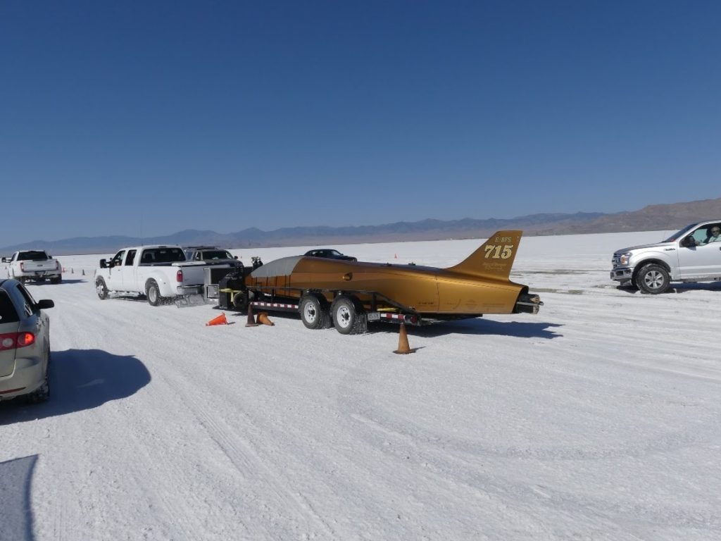
Links to the individual Part 1 articles on these airships are provided in Section 10.  Some individual articles cover more than one particular airship. Have fun exploring!

9. Assessment of near-term LTA market prospects

Among the new airships described in Part 1, the following advanced airship seems to be the best candidate for achieving type certification in the next five years:

  • LTA Research and Exploration (USA): Pathfinder 1 rigid airship, which is expected to make its first flight in 2024. The program appears to be well funded. 

The following airship manufacturers in Part 1 have advanced designs and they seem to be ready to manufacture a first commercial prototype if they can arrange adequate funding: 

  • AT2 Aerospace (USA): Their Z1 hybrid airship formerly was known as the Lockheed Martin LMH-1. In May 2023, Lockheed Martin exited the hybrid airship business without completing type certification and transitioned that business, including intellectual property and related assets, to the newly formed, commercial company ATAerospace.  In June, Straightline Aviation (a former LMH-1 customer) signed a Letter of Intent with ATAerospace, signaling commercial support for the Z1 hybrid airship.  
  • Aeros (USA): It seems that Aeros has been ready for more than a decade to begin type certification and manufacture a prototype of their Aeroscraft ML866 / Aeroscraft Gen 2 variable buoyancy / fixed volume airship.  The firm has reported successful subsystem tests.

Recent changes in European aviation regulations reduce some of the regulatory uncertainty for advanced airship type certification in the EU. The US FAA has not yet published comparable guidance for advanced airships, resulting in continuing regulatory uncertainty in the USA.

The promising airships in Part 1, as listed above, will be competing in the worldwide airship market with candidates identified in Modern Airships – Part 2, which potentially could enter the market in the same time frame. Among the airships described in Part 2, the following advanced airship seems to be the best candidate for achieving type certification in the next five years:

  • Flying Whales (France): The LCA60T rigid cargo airship was significantly redesigned in 2021, which resulted in a considerable schedule delay. In March 2023, Flying Whales reported that they expected to complete construction and flight testing of the first production prototype in the 2024 – 2025 timeframe, followed by EASA certification and start of industrial production in 2026.  The project appears to be well funded from diverse international sources in France, Canada, China and Morocco. Full-scale production facilities are planned in France, China and Canada and commercial airship operating infrastructure is being planned.
  • Hybrid Air Vehicles (UK): The Airlander 10 commercial passenger / cargo hybrid airship is being developed by HAV  based on their experience with the Airlander 10 prototype, which flew from 2016 to 2017. In 2022, Valencia, Spain-based Air Nostrum, which operates regional flights, ordered 10 Airlander 10 aircraft, with delivery scheduled for 2026. Also in 2022, Highlands and Islands Airport (HIAL) sponsored a study for introducing the Airlander 10 in Scotland. In April 2023, the regional UK government of South Yorkshire concluded a financial agreement that is expected to lead to the Airlander 10 being manufactured in Doncaster, in the north of England.  Things are moving in the right direction. However, FutureFlight reported that “the plan cannot proceed unless HAV secures a strategic investor. It needs at least £100 million to begin construction.”
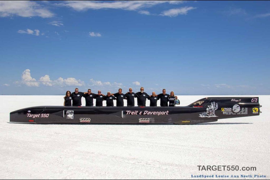
The following airship manufacturers in Part 2 have advanced designs and they seem to be ready to manufacture a first prototype if they can arrange funding: 

  • Aerovehicles (USA / Argentina): They claim their AV-10 non-rigid, multi-mission blimp can carry a 10 metric ton payload and be type certified within existing regulations for blimps. This should provide a lower-risk route to market for an airship with an operational capability that does not exist today.
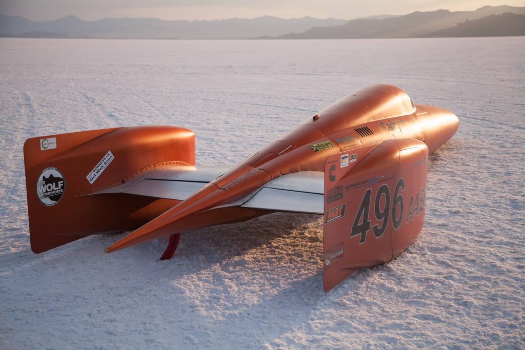
  • Atlas LTA Advanced Technology (Israel): After acquiring the Russian firm Augur RosAeroSystems in 2018, Atlas is continuing to develop the ATLANT variable buoyancy, fixed volume heavy lift airship.  They also are developing a new family of non-rigid Atlas-6 and -11 blimps and unmanned variants.  However, the development plans and schedules have not yet been made public.
  • BASI (Canada): The firm has a well-developed design in the MB-30T and a fixed-base operating infrastructure design that seems to be well suited for their primary market in the Arctic.
  • Euro Airship (France):  The firm reports having production-ready plans for their rigid airship designs. In June 2023, Euro Airship announced plans to build and fly a large rigid airship known as Solar Airship One around the world in 2026.
  • Millennium Airship (USA & Canada): The firm has well developed designs for their SF20T and SF50T SkyFreighters, has identified its industrial team for manufacturing, and has a business arrangement with SkyFreighter Canada, Ltd., which would become a future operator of SkyFreighter airships in Canada.  In addition, their development plan defines the work needed to build and certify a prototype and a larger production airship.

The 2020s will be an exciting time for the airship industry.  We’ll finally get to see if the availability of several different heavy-lift airships with commercial type certificates will be enough to open a new era in airship transportation. Aviation regulatory agencies need to help reduce investment risk by reducing regulatory uncertainty and putting in place an adequate regulatory framework for the wide variety of advanced airships being developed.  Customers with business cases for airship applications need to step up, place firm orders, and then begin the pioneering task of employing their airships and building a worldwide airship transportation network with associated ground infrastructure.  This will require consistent investment over the next decade or more before a basic worldwide airship transportation network is in place to support the significant use of commercial airships in cargo and passenger transportation and other applications. Perhaps then we’ll start seeing the benefits of airships as a lower environmental impact mode of transportation and a realistic alternative to fixed-wing aircraft, seaborne cargo vessels and heavy, long-haul trucks.

10.  Links to the individual articles

The following links will take you to the individual Modern Airships – Part 1 articles.  The organization of the following list matches the graphic table.

Note that several of these articles address more than one airship design from the same manufacturer / designer and they may be in different categories (i.e., Airship Industries, Ohio Airships, Walden Aerospace). These designs are listed separately in the above graphic tables and in the following index. The links listed below will take you to the correct article.

CONVENTIONAL AIRSHIPS

Conventional, rigid:

Conventional, semi-rigid airships:

Conventional, non-rigid airships (blimps):

VARIABLE BUOYANCY AIRSHIPS

Variable buoyancy, fixed volume airships:

SEMI-BUOYANT AIR VEHICLES

Semi-buoyant hybrid airships:

Semi-buoyant airplane / airship hybrids:

Helicopter / airship hybrids:

STRATOSPHERIC AIRSHIPS / HIGH-ALTITUDE PLATFORM STATIONS (HAPS)

PERSONAL GAS AIRSHIPS

THERMAL (HOT AIR) AIRSHIPS

HYBRID ROCKET / BALLOON (ROCKOON) AIRSHIPS

LTA DRONES

UNPOWERED AEROSTATS

Tethered aerostats (Kite balloons)

Tethered, heavy lift balloons:

Free-flying, high-altitude balloons:

Free-flying, manned, high-altitude balloons:

  • EosX – stratospheric passenger balloons: Coming soon
  • HaloSpace – stratospheric passenger balloons: Coming soon
  • Iwaya Giken – stratospheric passenger balloons: Coming soon
  • Space Perspective – stratospheric passenger balloons: Coming soon
  • StratoFlight – stratospheric passenger balloons: Coming soon
  • World View Enterprises Inc – stratospheric passenger balloons: Coming soon
  • Zephalto – stratospheric passenger balloons: Coming soon
  • Zero 2 Infinity – Bloon stratospheric passenger balloons: Coming soon