Peter Lobner, updated 17 November 2022
Kurzgesagt (German for “in a nutshell“) is a Munich-based design studio with a distinctive perspective on design and animation in the fields of education, science and commerce. For background information on Kurzgesagt, visit their website here: https://kurzgesagt.org/agency/
You’ll find their YouTube channel with a library of briefings at the following link: https://www.youtube.com/channel/UCsXVk37bltHxD1rDPwtNM8Q
From here you can navigate to many intriguing and entertaining animated briefings. Four Kurzgesagt briefings address the following questions regarding extraterrestrial life:
“The universe is unbelievably big – trillions of stars and even more planets. Soo… there just has to be life out there, right? But where is it? Why don’t we see any aliens? Where are they? And more importantly, what does this tell us about our own fate in this gigantic and scary universe?”
I hope you’ll enjoy these Kurzgesagt briefings:
The Fermi Paradox — Where Are All The Aliens? Part 1: https://www.youtube.com/watch?v=sNhhvQGsMEc

The Fermi Paradox — Where Are All The Aliens? Part 2: https://www.youtube.com/watch?v=1fQkVqno-uI
The Great Filter: Why Alien Life Would be our Doom: https://www.youtube.com/watch?v=UjtOGPJ0URM

What Do Alien Civilizations Look Like? The Kardashev Scale: https://www.youtube.com/watch?v=rhFK5_Nx9xY

Aliens under the Ice – Life on Rogue Planets: https://www.youtube.com/watch?v=M7CkdB5z9PY

For more information
- Matt Williams, “Beyond “Fermi’s Paradox” III: What is the Great Filter?,” Universe Today, 23 July 2020: https://www.universetoday.com/145512/beyond-the-fermi-paradox-iii-what-is-the-great-filter/
- Doug Adler, “The Great Filter: a possible solution to the Fermi Paradox,” Astronomy, 20 November 2020: https://astronomy.com/news/2020/11/the-great-filter-a-possible-solution-to-the-fermi-paradox
- Kelly Kizer Whitt & Deborah Byrd, “What is the Great Filter, and can we survive it?,” EarthSky, 17 November 2022: https://earthsky.org/space/avoiding-the-great-filter-earth-alien-civilizations/


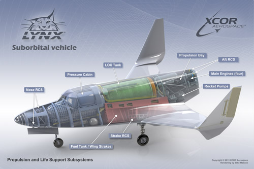
 Source: XCOR Aerospace
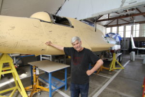 Build A Plane founder Lyn Freeman with unfinished Lynx prototype. Source: Douglas Messier/Space.com