All posts by Drummer

Landing a Reusable Booster Rocket on a Dime

Updated 18 March 2020

Peter Lobner

There are two U.S. firms that have succeeded in launching and recovering a booster rocket that was designed to be reusable. These firms are Jeff Bezos’ Blue Origin and Elon Musk’s SpaceX.   Their booster rockets are designed for very different missions.

  • Blue Origin’s New Shepard booster and capsule are intended for brief, suborbital flights for space tourism and scientific research. The booster and capsule will be “man-rated” for passenger-carrying suborbital missions.
  • In contrast, SpaceX’s Falcon 9 booster rocket is designed to deliver a variety of payloads to Earth orbit. The payload may be the SpaceX Dragon capsule or a different civilian or military spacecraft. Currently, the Falcon 9 booster and Dragon capsule are not “man-rated” for orbital missions. SpaceX is developing a crewed version of the Dragon capsule that, in the future, will be used to deliver and return crewmembers for the International Space Station (ISS).

Both firms cite a cost advantage of recovering and reusing an expensive booster rocket and space capsule. Let’s see how they’re doing.

Blue Origin

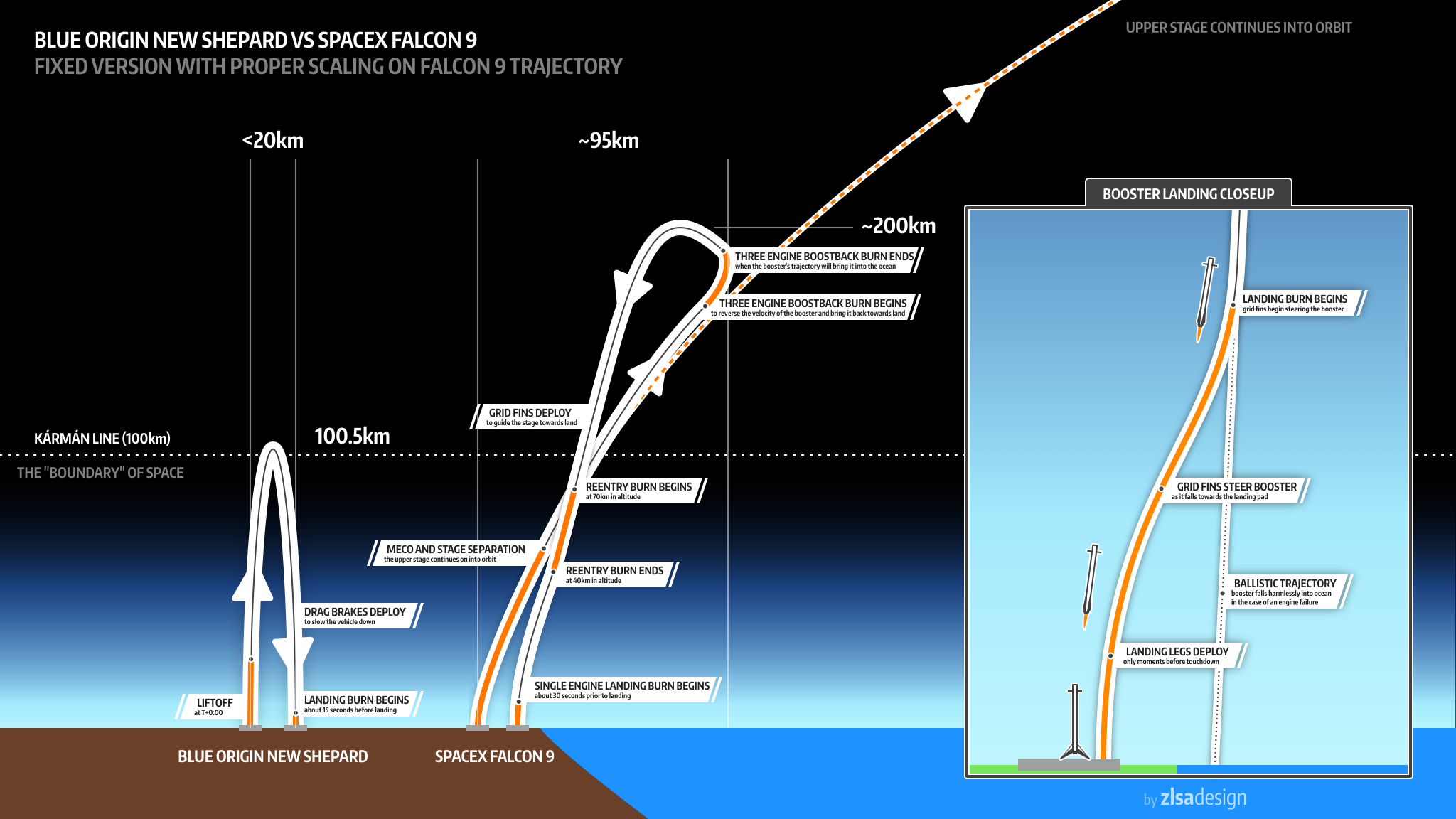
The basic flight profiles of a single-stage, single engine New Shepard booster and capsule are shown in the following diagram. The primary goals of each flight are to boost the capsule and passengers above 62.1 miles (100 km), safely recover the capsule and passengers, and safely recover the booster rocket. You can see in the diagram that the booster rocket and the capsule separate after the booster’s rocket engine is shutdown and they are recovered separately. At separation, the booster and capsule are traveling at about Mach 3 (about 1,980 mph, 3,186 kph). The orientation of the booster rocket is controlled during descent and the rocket engine is restarted once at low altitude to bring the booster to a soft, vertical landing. Both the booster rocket and the capsule are designed for reuse.
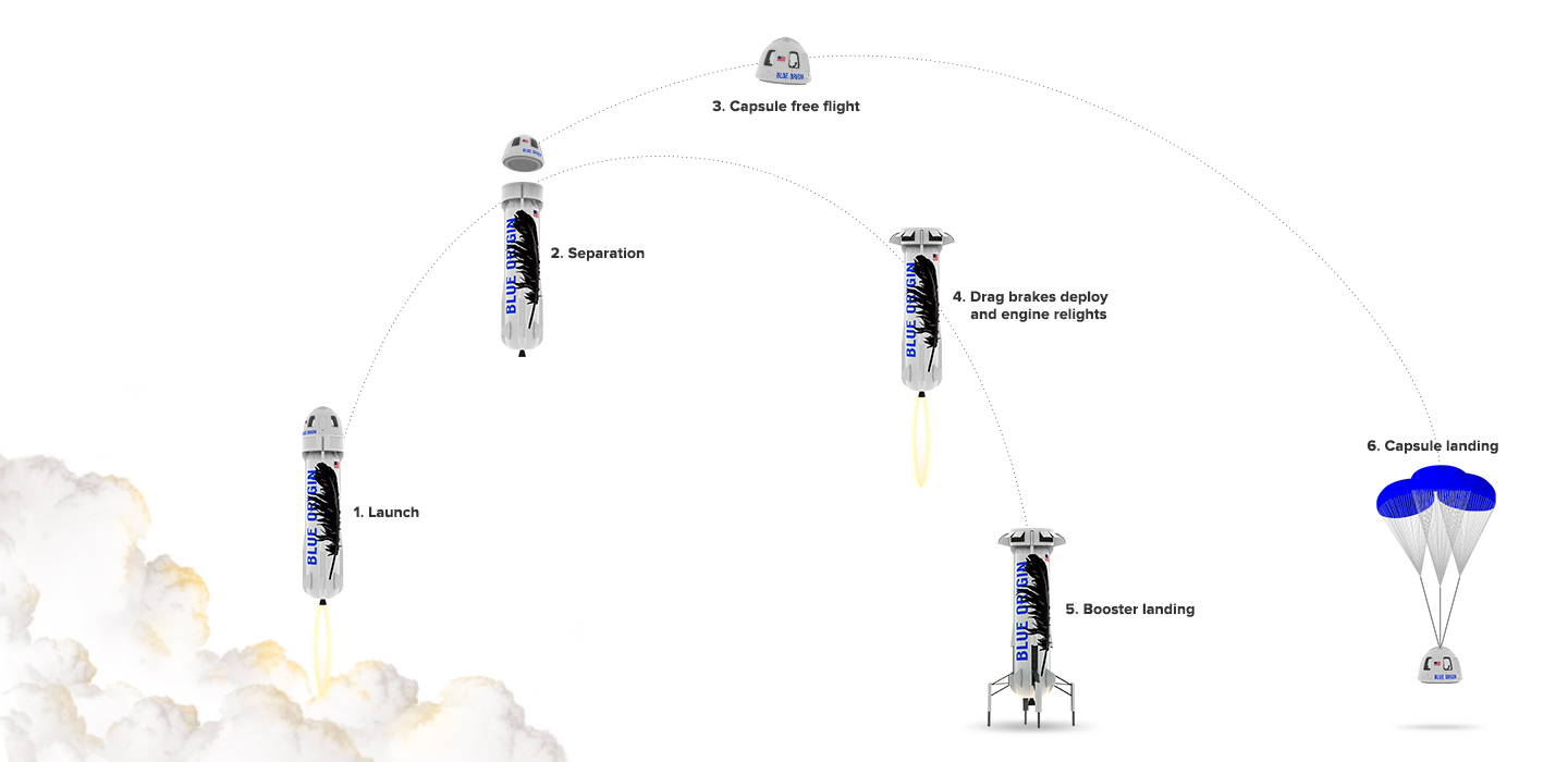
Blue-origin-flight-profileSource: Blue Origin

On 23 November 2015, Blue Origin made history when, on its first attempt, the New Shepard booster completed a suborbital flight that culminated with the autonomous landing of the booster rocket near the launch site in west Texas. The capsule landed nearby under parachutes. You can view a video of this historic flight at the following link:

https://www.youtube.com/watch?v=9pillaOxGCo

This same New Shepard booster was launched again on 22 January 2016, completed the planned suborbital flight, and again made an autonomous safe landing. This flight marked the first reuse of a booster rocket.

Again using the same hardware, New Shepard was launched on its third flight and safely recovered on 2 April 2016. On this flight, the rocket engine was re-started at a lower altitude (3,635 feet, 1,107 m) than on the previous flights to demonstrate the fast startup of the engine. The booster rocket made an on-target landing, touching down at a velocity of 4.8 mph (7.7 kph).
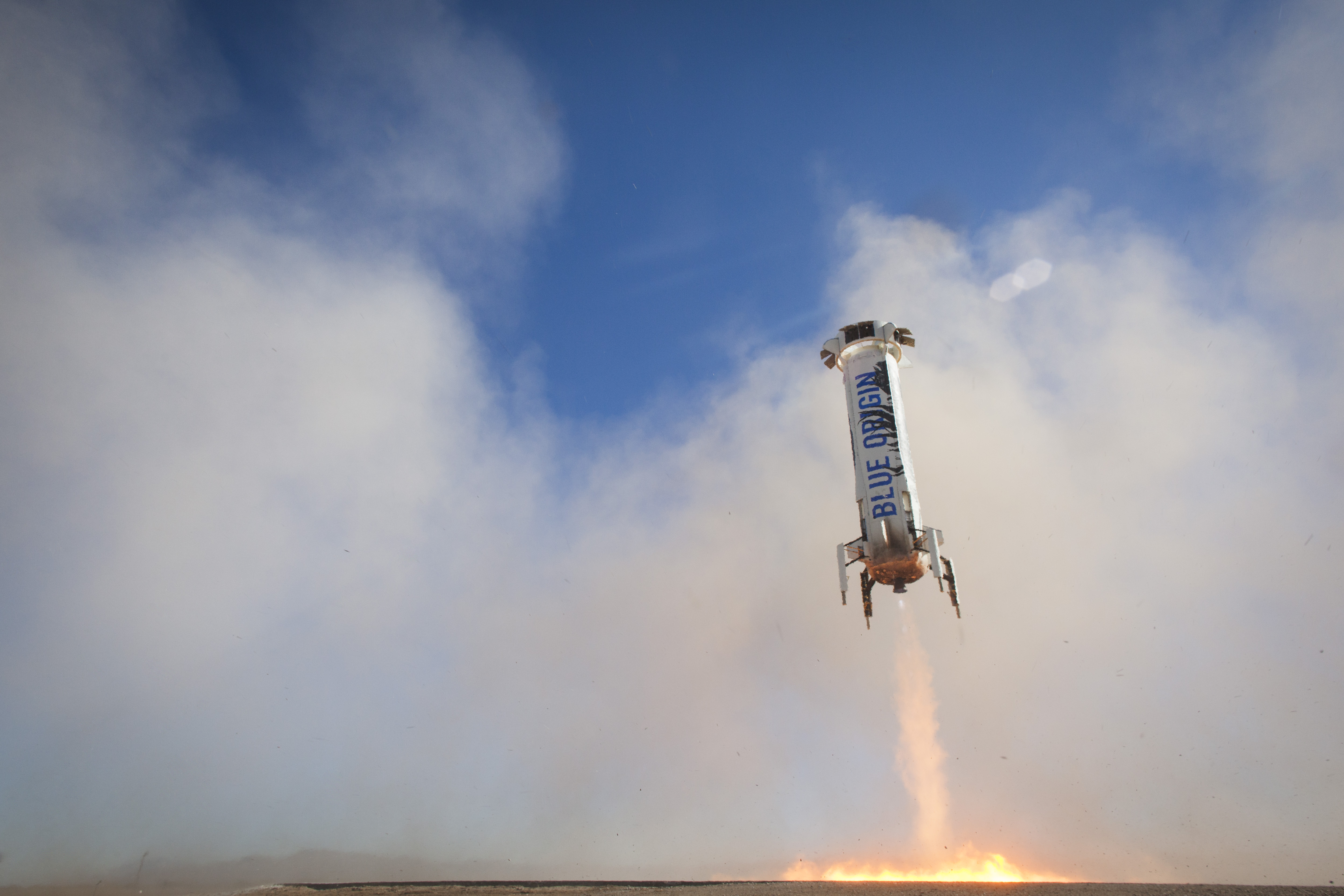
New Shepard landing 3Source: Blue Origin

You can view a short video of the third New Shepard flight at the following link:

https://www.blueorigin.com/news/news/pushing-the-envelope#youtubeYU3J-jKb75g

In this video, the view from the capsule at 64.6 miles (104 km) above the Earth is stunning. As the landing of the booster rocket approaches, it is dropping like a stone until the rocket engine powers up, quickly stops the descent, and brings the booster rocket in for an accurate, soft, vertical landing.

So, the current score for Blue Origin is 3 attempts and 3 successful soft, vertical landings in less than 5 months. The same New Shepard booster was used all three times (i.e., it has been reused twice).

Refer to the Blue Origin website at the following link for more information.

https://www.blueorigin.com

SpaceX Falcon 9 (F9R)

The basic flight profile for a two-stage Falcon 9 recoverable booster on an orbital mission is shown in the following diagram. For ISS re-supply missions, the target for the Dragon capsule is in a near-circular orbit at an altitude of about 250 miles (403 km) and an orbital velocity of about 17,136 mph (27,578 kph). The first stage shuts down and separates from the second stage at an altitude of about 62.1 miles (100 km) and a speed of about 4,600 mph (7,400 kph, Mach 7). These parameters are for illustrative purposes only and will vary as needed to meet the particular mission requirements. The second stage continues into orbit with a Dragon capsule or other payload.

The nine-engine first stage carries extra fuel to enable some of the booster rockets to re-start three times after stage separation to adjust trajectory, decelerate, and make a soft vertical landing on an autonomous recovery barge floating in the ocean 200 miles (320 km) or more downrange from the launch site.

The empty weight of the recoverable version of the Falcon 9 first stage (the F9R) is 56,438 pounds (25,600 kg,), which is about 5,511 pounds (2,500 kg) more than the basic, non-recoverable version (V1.1). The added fuel and structural weight to enable recovery of the first stage reduces the payload mass that can be delivered to orbit.

Falcon flight profile to barge landingSource: SpaceX

The autonomous “drone” barge is a very small target measuring about 170 ft. × 300 ft. (52 m × 91 m). It is equipped with azimuthal thrusters that provide precise positioning using GPS position data. The Falcon 9 booster knows where the drone barge should be. The Falcon 9’s four landing legs span 60 ft. (18 m), and all must land on the barge.
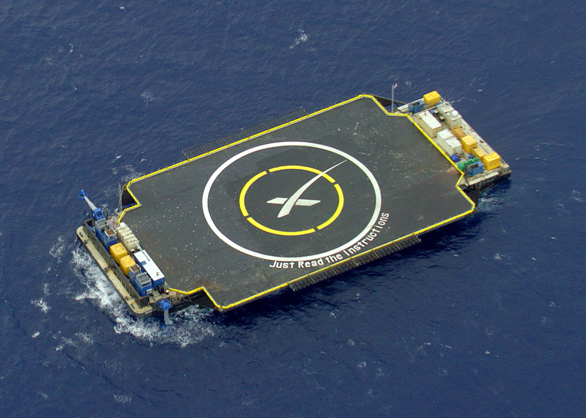
SpaceX_ASDSSource: SpaceX

SpaceX made a series of unsuccessful attempts to land on a drone barge before their first successful landing:

  • 10 January 2015: First attempt; hard landing; booster destroyed.
  • 11 February 2015: High seas prevented use of the barge. Instead, the Falcon 9 first stage was flown to a soft, vertical landing in the ocean, simulating a barge landing.
  • 14 April 2015: Second attempt; successful vertical landing but the booster toppled, likely due to remaining lateral momentum.
  • 7 January 2016: Third attempt; successful vertical landing but the booster toppled, likely due to a mechanical failure in one landing leg.
  • 4 March 2016: Fourth attempt, with low fuel reserve and using only three engines; hard landing; booster destroyed.

On 8 April 2016, a Falcon 9 booster was launched from Cape Canaveral on an ISS re-supply mission. The first stage of this booster rocket became the first to make a successful landing on the drone barge downrange in the Atlantic.
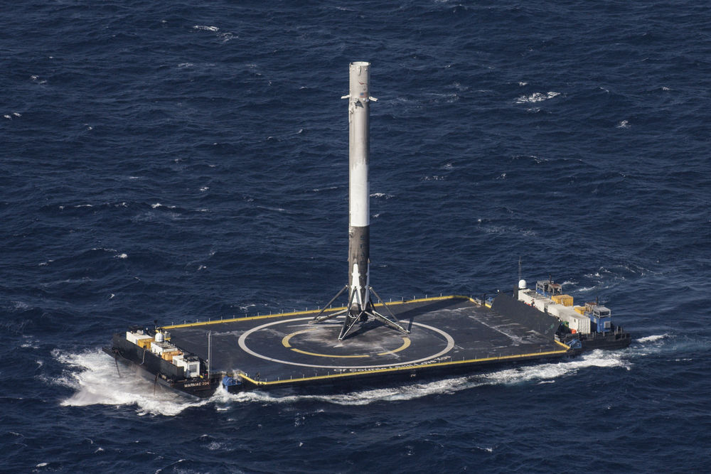
A002_C002_0408A9Source: SpaceX

You can view a short video of the Falcon 9 booster landing on the drone barge at the following link:

https://www.youtube.com/watch?v=RPGUQySBikQ

In the video, you will note the barge heaving in the moderate seas. After landing, the 156 foot (47.5 m) tall booster rocket is just balanced on its landing legs. Before the barge can be towed back to port, crew must board the barge and secure the booster. This is done by placing “shoes” over the landing feet and welding the shoes to the deck of the barge. Once back at Cape Canaveral, the booster will be examined and the rocket engine will be test fired to determine if the first stage can be reused.

Previously, on 21 December 2015, SpaceX successfully launched its Falcon 9 booster on an orbital mission and then landed the first stage back on the ground at Cape Canaveral. As shown in the diagram below, this involved a very different flight profile than for a Falcon 9 flight with a landing on the downrange drone barge. For the December 2015 flight, the Falcon 9 first stage had to reverse direction to fly back to Cape Canaveral from about 59 miles (95 km) downrange and then decelerate and maneuver for a soft, vertical landing about 10 minutes after launch.

Blue Origin-Falcon flight profile comparedSource: SpaceX

After recovering the booster, the Falcon 9 was inspected and the engines were successfully re-tested on 15 January 2016, on a launch pad at Cape Canaveral. I could not determine if this Falcon 9 first stage has been reused.

So, the current score for SpaceX is 6 attempts (not counting the February 2015 soft landing in the ocean) and 2 successes (one on land and one on the drone barge) in 15 months.

Refer to the SpaceX website at the following link for more information.

http://www.spacex.com

The bottom line

In the above diagram for the December 2015 Falcon 9 flight, the relative complexity of a typical New Shepard flight profile and the Falcon 9 flight profile with return to Cape Canaveral is clear. The Falcon 9 flight profile for a landing on the small, moving, down-range drone barge is even more complex.

The New Shepard sub-orbital mission is much less challenging than any Falcon 9 orbital mission. Nonetheless, both booster rockets face very similar challenges as they approach the landing site to execute an autonomous, soft, vertical landing.

Both Blue Origin and SpaceX have made tremendous technological leaps in demonstrating that a booster rocket can make an autonomous, soft, vertical landing and remain in a condition that allows its reuse in a subsequent mission. Blue Origin actually has reused their booster rocket and capsule twice, further demonstrating the maturity of reusable rocket technology.

It remains to be seen if this technology actually delivers the operating cost savings anticipated by Blue Origin and SpaceX. I hope it does. When space tourism becomes a reality, the hoped-for cost benefits of reusable booster rockets and spacecraft could affect my ticket price.

18 March 2020 Update:  Four years later

On 6 March 2020, SpaceX launched its 20th commercial resupply services mission (CRS-20) to the International Space Station (ISS).  The successful launch concluded with the 50thsuccessful landing of the first stage of a Falcon 9 launch vehicle.  On this mission, the first stage flew back for a landing at Cape Canaveral in the windiest conditions encountered to date, 25 to 30 mph.  This was the last launch with the original cargo-only version of the Dragon capsule. Subsequent launches will use 2nd-generation Dragon capsules that are roomier and designed to also accommodate astronauts.

About two weeks later, on 18 March 2020, SpaceX launched another successful Falcon 9 mission, for the first time using a first stage that had flown on four prior missions.  The satellite payload was launched into the intended orbit.  However, a malfunction in one of nine first stage engines prevented recovery of the booster rocket.

On 11 December 2019, Blue Origin reported that New Shepard mission NS-12 was successfully completed.  “This was the 6th flight for this particular New Shepard vehicle. Blue Origin has so far reused two boosters five times each consecutively, so today marks a record with this booster completing its 6th flight to space and back.”

Booster reusability has become a reality for SpaceX and Blue Origin, and other firms are following their lead by developing new reusable launch vehicles.  These are encouraging steps toward more economic access to Earth orbit and beyond.  Both SpaceX and Blue Origin have advanced reusable launch vehicle technology significantly in the past four years.  Both soon will begin human space flight using their respective launch vehicles and space capsules.

Polymagnets® will Revolutionize the Ways in Which Magnets are Used

Peter Lobner

The U.S firm Correlated Magnetics Research (CMR), Huntsville, AL, invented and is the sole manufacturer of Polymagnets®, which are precision-tailored magnets that enhance existing and new products with specific behaviors that go far beyond the simple attract-and-repel behavior of common magnets. Polymagnets have been granted over 100 patents, all held by CMR. You can visit their website at the following link:

http://www.polymagnet.com

CMR describes Polymagnets® as follows:

“Essentially programmable magnets, Polymagnets are the first fundamental advance in magnets in 180 years, since the introduction of electromagnets. With Polymagnets, new products can have softer ‘feel’ or snappier or crisper closing or opening behavior, and may be given the sensation of a spring or latch”.

On a conventional magnet, there is a North (N) pole on one surface and a South (S) pole on the opposite surface. Magnetic field lines flow around the magnetic from pole to pole. On a Polymagnet®, many small, polarized (N or S) magnetic pixels (“maxels”) are manufactured by printing in a desired pattern on the same surface. The magnetic field lines are completed between the maxels on that surface, resulting in a very compact, strong magnetic field. This basic concept is shown in the following figure.

Polymagnet field comparison

The mechanical 3-D behavior of a Polymagnet® is determined by the pattern and strength of the maxels embedded on the surface of the magnet. These customizable behaviors include spring, latch, shear, align, snap, torque, hold, twist, soften and release. The very compact magnetic field reduces magnetic interference with other equipment, opening new applications for Polymagnets® where a conventional magnet wouldn’t be suitable.

The above figure is a screenshot from the Smarter Every Day 153 video, which you can view at the following link. Thanks to Mike Spaeth for sending me this is a 10-minute video, which I think you will enjoy.

https://www.youtube.com/watch?v=IANBoybVApQ

More information on Polymagnet® technology, including short videos that demonstrate different mechanical behaviors, and a series of downloadable white papers, is available at the following link.

http://www.polymagnet.com/polymagnets/

This is remarkable new technology in search of novel applications. Many practical applications are identified on the Polymagnet® website. What are your ideas?

If you really want to look into this technology, you can buy a Polymagnet® demonstration kit at the following links:

https://www.magnetics.com/product.asp?ProductID=164

or,

http://www.mechanismsmarket.com/kits/

Polymagnet demo kit   Source: Mechanisms Market

Large Autonomous Vessels will Revolutionize the U.S. Navy

Peter Lobner

In this post, I will describe two large autonomous vessels that are likely to revolutionize the way the U.S. Navy operates. The first is the Sea Hunter, originally sponsored by Defense Advanced Projects Agency (DARPA), and the second is Echo Voyager developed by Boeing.

DARPA Anti-submarine warfare (ASW) Continuous Trail Unmanned Vessel (ACTUV)

ACTUV conceptSource: DARPA

DARPA explains that the program is structured around three primary goals:

  • Demonstrate the performance potential of a surface platform conceived originally as an unmanned vessel.
    • This new design paradigm reduces constraints on conventional naval architecture elements such as layout, accessibility, crew support systems, and reserve buoyancy.
    • The objective is to produce a vessel design that exceeds state-of-the art manned vessel performance for the specified mission at a fraction of the vessel size and cost.
  •  Advance the technology for unmanned maritime system autonomous operation.
    • Enable independently deploying vessels to conduct missions spanning thousands of kilometers of range and months of duration under a sparse remote supervisory control model.
    • This includes autonomous compliance with maritime laws and conventions for safe navigation, autonomous system management for operational reliability, and autonomous interactions with an intelligent adversary.
  • Demonstrate the capability of an ACTUV vessel to use its unique sensor suite to achieve robust, continuous track of the quietest submarine targets over their entire operating envelope.

While DARPA states that ACTUV vessel is intended to detect and trail quiet diesel electric submarines, including air-independent submarines, that are rapidly proliferating among the world’s navies, that detect and track capability also should be effective against quiet nuclear submarines. The ACTUV vessel also will have capabilities to conduct counter-mine missions.

The ACTUV program is consistent with the Department of Defense (DoD) “Third Offset Strategy,” which is intended to maintain U.S. military technical supremacy over the next 20 years in the face of increasing challenges from Russia and China. An “offset strategy” identifies particular technical breakthroughs that can give the U.S. an edge over potential adversaries. In the “Third Offset Strategy”, the priority technologies include:

  • Robotics and autonomous systems: capable of assessing situations and making decisions on their own, without constant human monitoring
  • Miniaturization: enabled by taking the human being out of the weapons system
  • Big data: data fusion, with advanced, automated filtering / processing before human involvement is required.
  • Advanced manufacturing: including composite materials and additive manufacturing (3-D printing) to enable faster design / build processes and to reduce traditionally long supply chains.

You can read more about the “Third Offset Strategy” at the following link:

http://breakingdefense.com/2014/11/hagel-launches-offset-strategy-lists-key-technologies/

You also may wish to read my 19 March 2016 post on Arthur C. Clarke’s short story “Superiority.” You can decide for yourself if it relates to the “Third Offset Strategy.”

Leidos (formerly SAIC) is the prime contractor for the ACTUV technology demonstrator vessel, Sea Hunter. In August 2012, Leidos was awarded a contract valued at about $58 million to design, build, and operationally test the vessel.

In 2014, Leidos used a 32-foot (9.8 meter) surrogate vessel to demonstrate the prototype maritime autonomy system designed to control all maneuvering and mission functions of an ACTUV vessel. The first voyage of 35 nautical miles (65.8 km) was conducted in February 2014. A total of 42 days of at-sea demonstrations were conducted to validate the autonomy system.

Sea Hunter is an unarmed 145-ton full load displacement, diesel-powered, twin-screw, 132 foot (40 meters) long, trimaran that is designed to a wide range of sea conditions. It is designed to be operational up to Sea State 5 [moderate waves to 6.6 feet (2 meters) height, winds 17 – 21 knots] and to be survivable in Sea State 7 [rough weather with heavy waves up to 20 feet (6 meters) height]. The vessel is expected to have a range of about 3,850 miles (6,200 km) without maintenance or refueling and be able to deploy on missions lasting 60 – 90 days.

Sea Hunter side view cropSource: DARPA

Raytheon’s Modular Scalable Sonar System (MS3) was selected as the primary search and detection sonar for Sea Hunter. MS3 is a medium frequency sonar that is capable of active and passive search, torpedo detection and alert, and small object avoidance. In the case of Sea Hunter, the sonar array is mounted in a bulbous housing at the end of a fin that extends from the bottom of the hull; looking a bit like a modern, high-performance sailboat’s keel.

Sea Hunter will include sensor technologies to facilitate the correct identification of surface ships and other objects on the sea surface. See my 8 March 2015 post on the use of inverse synthetic aperture radar (ISAR) in such maritime surveillance applications.

During a mission, an ACTUV vessel will not be limited by its own sensor suit. The ACTUV vessel will be linked via satellite to the Navy’s worldwide data network, enabling it to be in constant contact with other resources (i.e., other ships, aircraft, and land bases) and to share data.

Sea Hunter was built at the Vigor Shipyard in Portland, Oregon. Construction price of the Sea Hunter is expected to be in the range from $22 to $23 million. The target price for subsequent vessels is $20 million.

You can view a DARPA time-lapse video of the construction and launch of Sea Hunter at the following link:

http://www.darpa.mil/attachments/ACTUVTimelapseandWalkthrough.mp4

Sea Hunter launch 1Source: DARPA

Sea Hunter lauunch 2Source: DARPA

In the above photo, you can see on the bottom of the composite hull, just forward of the propeller shafts, what appears to be a hatch. I’m just speculating, but this may be the location of a retractable sonar housing, which is shown in the first and second pictures, above.

You can get another perspective of the launch and the subsequent preliminary underway trials in the Puget Sound in the DARPA video at the following link:

http://www.darpa.mil/attachments/ACTUVTimelapseandWalkthrough.mp4

During the speed run, Sea Hunter reached a top speed of 27 knots. Following the preliminary trials, Sea Hunter was christened on 7 April 2016. Now the vessel starts an operational test phase to be conducted jointly by DARPA and the Office of Naval Research (ONR). This phase is expected to run through September 2018.

DARPA reported that it expects an ACTUV vessel to cost about $15,000 – $20,000 per day to operate. In contrast, a manned destroyer costs about $700,000 per day to operate.

The autonomous ship "Sea Hunter", developed by DARPA, is shown docked in Portland, Oregon before its christening ceremonySource: DARPA

You can find more information on the ACTUV program on the DARPA website at the following link:

http://www.darpa.mil/news-events/2016-04-07

If ACTUV is successful in demonstrating the expected search and track capabilities against quiet submarines, it will become the bane of submarine commanders anywhere in the world. Imagine the frustration of a submarine commander who is unable to break the trail of an ACTUV vessel during peacetime. During a period of conflict, an ACTUV vessel may quickly become a target for the submarine being trailed. The Navy’s future conduct of operations may depend on having lots of ACTUV vessels.

28 July 2016 update: Sea Hunter ACTUV performance testing

On 1 May 2016, Sea Hunter arrived by barge in San Diego and then started initial performance trial in local waters.

ACTUV in San Diego BaySource: U.S. Navy

You can see a video of Sea Hunter in San Diego Bay at the following link:

https://news.usni.org/2016/05/04/video-navys-unmanned-sea-hunter-arrives-in-san-diego

On 26 July 2016, Leidos reported that it had completed initial performance trials in San Diego and that the ship met or surpassed all performance objectives for speed, maneuverability, stability, seakeeping, acceleration, deceleration and fuel consumption. These tests were the first milestone in the two-year test schedule.

Leidos indicated that upcoming tests will exercise the ship’s sensors and autonomy suite with the goals of demonstrating maritime collision regulations compliance capability and proof-of-concept for different Navy missions.

4 October 2018 update:  DARPA ACTUV program completed.  Sea Hunter testing and development is being continued by the Office of Naval Research

In January 2018, DARPA completed the ACTUV program and the Sea Hunter was transferred to the Office of Naval Research (ONR), which is continuing to operate the technology demonstration vessel under its Medium Displacement Unmanned Surface Vehicle (MDUSV) program.  You can read more about the transition of the DARPA program to ONR here:
 
 
It appears that ONR is less interested in the original ACTUV mission and more interested in a general-purpose “autonomous truck” that can be configured for a variety of missions while using the basic autonomy suite demonstrated on Sea Hunter.  In December 2017, ONR awarded Leidos a contract to build the hull structure for a second autonomous vessel that is expected to be an evolutionary development of the original Sea Hunter design.  You can read more about this ONR contract award here:
 

Echo Voyager Unmanned Underwater Vehicle (UUV)

Echo Explorer - front quarter viewSource: BoeingEcho Explorer - top openSource: Boeing

Echo Voyager is the third in a family of UUVs developed by Boeing’s Phantom Works. The first two are:

  • Echo Ranger (circa 2002): 18 feet (5.5 meters) long, 5 tons displacement; maximum depth 10,000 feet; maximum mission duration about 28 hours
  • Echo Seeker (circa 2015): 32 feet (9.8 meter) long; maximum depth 20,000 feet; maximum mission duration about 3 days

Both Echo Ranger and Echo Seeker are battery powered and require a supporting surface vessel for launch and recovery at sea and for recharging the batteries. They successfully have demonstrated the ability to conduct a variety of autonomous underwater operations and to navigate safely around obstacles.

Echo Voyager, unveiled by Boeing in Huntington Beach, CA on 10 March 2016, is a much different UUV. It is designed to deploy from a pier, autonomously conduct long-duration, long-distance missions and return by itself to its departure point or some other designated destination. Development of Echo Voyager was self-funded by Boeing.

Echo Voyager is a 50-ton displacement, 51 foot (15.5 meters) long UUV that is capable of diving to a depth of 11,000 feet (3,352 meters). It has a range of about 6,500 nautical miles (12,038 km), and is expected to be capable of autonomous operations for three months or more. The vessel is designed to accommodate various “payload sections” that can extend the length of the vessel up to a maximum of 81 feet (24.7 meters).

You can view a Boeing video on the Echo Voyager at the following link:

https://www.youtube.com/watch?v=L9vPxC-qucw

The propulsion system is a hybrid diesel-electric rechargeable system. Batteries power the main electric motor, enabling a maximum speed is about 8 knots. Electrically powered auxiliary thrusters can be used to precisely position the vessel at slow speed. When the batteries require recharging,

The propulsion system is a hybrid diesel-electric rechargeable system. Batteries power the main electric motor, enabling a maximum speed is about 8 knots. Electrically powered auxiliary thrusters can be used to precisely position the vessel at slow speed. When the batteries require recharging, Echo Voyager will rise toward the surface, extend a folding mast as shown in the following pictures, and operate the diesel engine with the mast serving as a snorkel. The mast also contains sensors and antennae for communications and satellite navigation.

Echo Explorer - mast extendingSource: screenshot from Boeing video at link aboveEcho Explorer - snorkelingSource: screenshot from Boeing video at link above

The following image, also from the Boeing video, shows deployment of a payload onto the seabed.Echo Explorer - emplacing on seabedSource: screenshot from Boeing video at link above

Initial sea trials off the California coast were conducted in mid-2016.

Boeing currently does not have a military customer for Echo Voyager, but foresees the following missions as being well-suited for this type of UUV:

  • Surface and subsurface intelligence, surveillance, and reconnaissance (ISR)
  • ASW search and barrier patrol
  • Submarine decoy
  • Critical infrastructure protection
  • Mine countermeasures
  • Weapons platform

Boeing also expects civilian applications for Echo Voyager in offshore oil and gas, marine engineering, hydrography and other scientific research.

4 October 2018 update:  Progress in Echo Voyager development

Echo Voyager is based at a Boeing facility in Huntington Beach, CA.  In June 2018, Boeing reported that Echo Voyager had returned to sea for a second round of testing.  You can read more on Echo Voyager current status and the Navy’s plans for future large UUVs here:

http://www.latimes.com/business/la-fi-boeing-echo-voyager-20180623-story.html

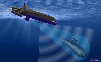
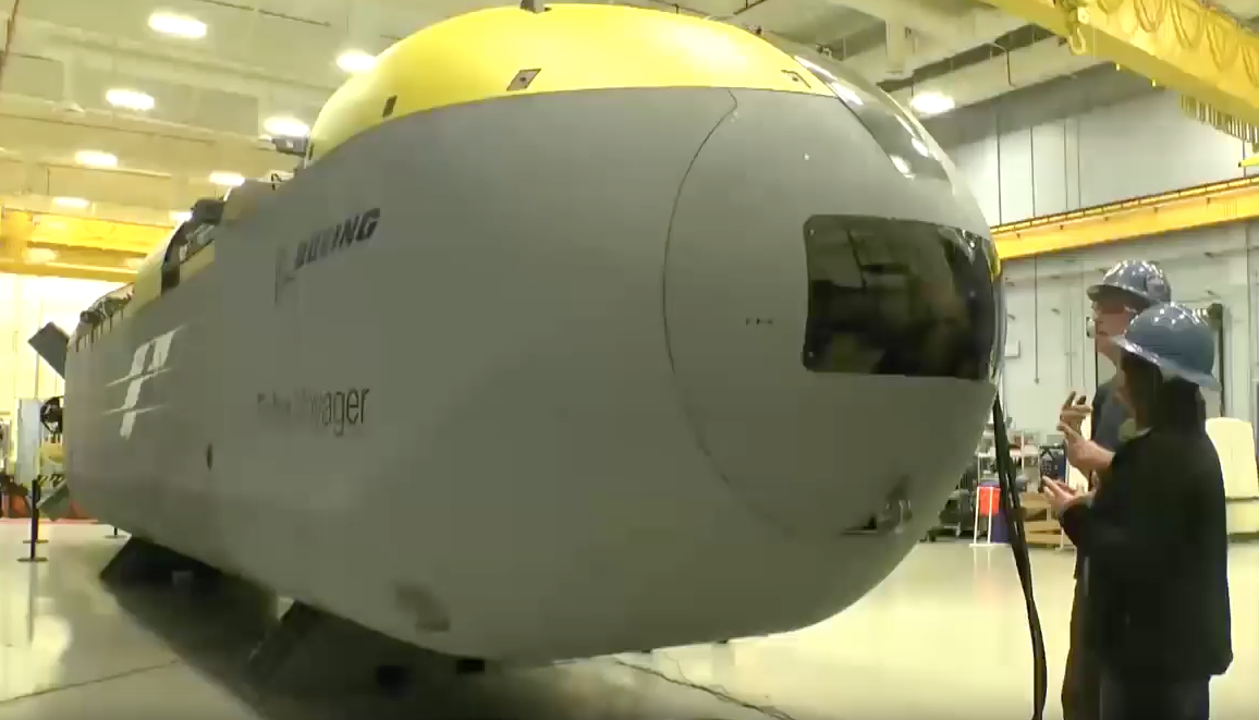
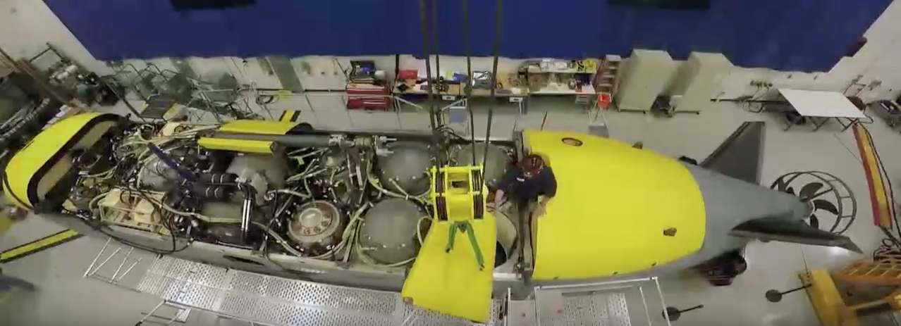
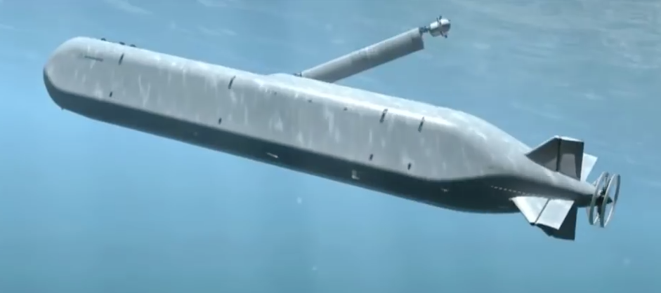
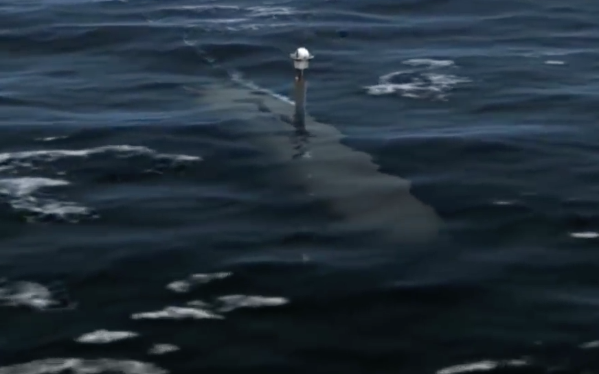
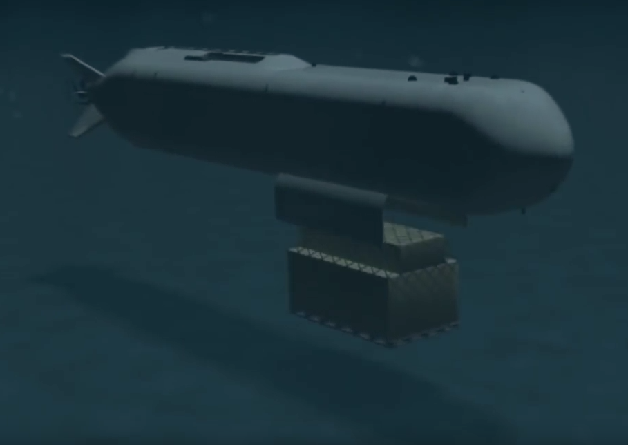
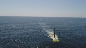
Echo Voyager operating near the surface with mast extended. Source.  Boeing

The Invisible Man may be Blind!

Peter Lobner

Metamaterials are a class of material engineered to produce properties that don’t occur naturally.

The first working demonstration of an “invisibility cloak” was achieved in 2006 at the Duke University Pratt School of Engineering using the complex metamaterial-based cloak shown below.

Duke 2006 metamaterial cloakSource: screenshot from YouTube link below.

The cloak deflected an incoming microwave beam around an object and reconstituted the wave fronts on the downstream side of the cloak with little distortion. To a downstream observer, the object inside the cloak would be hidden.

Effect of Duke metamaterial cloakSource: screenshot from YouTube link below.

You can view a video of this Duke invisibility cloak at the following link:

https://www.youtube.com/watch?v=Ja_fuZyHDuk

In a paper published in the 18 September 2015 issue of Science, researchers at UC Berkley reported creating an ultra-thin, metamaterial-based optical cloak that was successful in concealing a small scale, three-dimensional object. The abstract of this paper, “An ultrathin invisibility skin cloak for visible light”, by Ni et al., is reproduced below.

“Metamaterial-based optical cloaks have thus far used volumetric distribution of the material properties to gradually bend light and thereby obscure the cloaked region. Hence, they are bulky and hard to scale up and, more critically, typical carpet cloaks introduce unnecessary phase shifts in the reflected light, making the cloaks detectable. Here, we demonstrate experimentally an ultrathin invisibility skin cloak wrapped over an object. This skin cloak conceals a three-dimensional arbitrarily shaped object by complete restoration of the phase of the reflected light at 730-nanometer wavelength. The skin cloak comprises a metasurface with distributed phase shifts rerouting light and rendering the object invisible. In contrast to bulky cloaks with volumetric index variation, our device is only 80 nanometer (about one-ninth of the wavelength) thick and potentially scalable for hiding macroscopic objects.”

If you have a subscription to Science, you can read the full paper at the following link:

http://science.sciencemag.org/content/349/6254/1310

Eric Grundhauser writes on the Atlas Obscura website about an interesting quandary for users of an optical invisibility cloak.

“Since your vision is based on the light rays that enter your eyes, if all of these rays were diverted around someone under an invisibility cloak, the effect would be like being covered in a thick blanket. Total darkness.”

So, the Invisible Man is likely to be less of a threat than he appeared in the movies. You should be able to locate him as he stumbles around a room, bumping into everything he can’t see at visible light frequencies. However, he may be able to navigate and sense his adversary at other electromagnetic and/or audio frequencies that are less affected by his particular invisibility cloak.

You can read Eric Grundhauser’s complete article, “The Problem With Invisibility is Blindness,” at the following link:

http://www.atlasobscura.com/articles/the-problem-with-invisibility-is-the-blindness?utm_source=howtogeek&utm_medium=email&utm_campaign=newsletter

Recognizing this inconvenient aspect of an invisibility cloak, researchers from Yunnan University, China, have been investigating the concept of a “reciprocal cloak,” which they describe as, “an intriguing metamaterial device, in which a hidden antenna or a sensor can receive electromagnetic radiation from the outside but its presence will not be detected.” One approach is called an “open cloak,” which includes a means to, “open a window on the surface of a cloak, so that exchanging information and matter with the outside can be achieved.”

You can read the complete 2011 paper, “Electromagnetic Reciprocal Cloak with Only Axial Material Parameter Spatially Variant,” by Yang et al., at the following link:

http://www.hindawi.com/journals/ijap/2012/153086/

An all-aspect, broadband (wide range of operational frequencies) invisibility cloak is likely to remain in the realm of fantasy and science fiction. A 10 March 2016 article entitled, “Invisibility cloaks can never hide objects from all observers,” by Lisa Zyga, explains:

“….limitations imposed by special relativity mean that the best invisibility cloaks would only be able to render objects partially transparent because they would suffer from obvious visible distortions due to motion. The result would be less Harry Potter and more like the translucent creatures in the 1987 movie Predator.”

You can read the complete article at the following link:

http://phys.org/news/2016-03-invisibility-cloaks.html

Further complications are encountered when applying an invisibility cloak to a very high-speed vessel. A 28 January 2016 article, also by Lisa Zyga, explains:

“When the cloak is moving at high speeds with respect to an observer, relativistic effects shift the frequency of the light arriving at the cloak so that the light is no longer at the operational frequency. In addition, the light emerging from the cloak undergoes a change in direction that produces a further frequency shift, causing further image distortions for a stationary observer watching the cloak zoom by.”

You can read the complete article, “Fast-moving invisibility cloaks become visible,” at the following link:

http://phys.org/news/2016-01-fast-moving-invisibility-cloaks-visible.html

So, there you have it! The Invisible Man may be blind, the Predator’s cloak seems credible even when he’s moving, and a really fast-moving cloaked Klingon battlecruiser is vulnerable to detection.

Internet Archive: a Great Access Point to Many Web Resources and Vintage Science Fiction

Peter Lobner

Internet Archive is a non-profit library of millions of free books, audio books, movies, music, software and more, which you can access at the following link:

https://archive.org

It’s hard to navigate this site to find out what’s there. The home page presents icons for the “Top Collections in the Archive,” but you have to scroll through many pages to view hundreds of these icons, each of which links to a corresponding collection. Interesting collections I found include:

  • American Libraries
  • The Library of Congress
  • The LibriVox Free Audiobook Collection
  • Software Library: MS-DOS Games
  • Computer Magazine Archives
  • Television Archive
  • Grateful Dead
  • Metropolitan Museum of Art Gallery Images
  • Kahn Academy

Archive icons

There’s a Pulp Magazine Archive at the following link:

https://archive.org/details/pulpmagazinearchive

Once there, select Topic: “science fiction”, or use the following direct link:

https://archive.org/details/pulpmagazinearchive?and%5B%5D=subject%3A%22science+fiction%22&sort=-downloads&page=2

Then you’re on your way to libraries of vintage science fiction.  Below are results from my own searches.

Galaxy Science Fiction:

Galaxy Science Fiction was an American digest-size science fiction magazine published from 1950 to 1980. It was founded by an Italian company, World Editions, to help it break in to the American market. World Editions hired as editor H. L. Gold, who rapidly made Galaxy the leading science fiction magazine of its time, focusing on stories about social issues rather than technology.

The Galaxy Science Fiction archive, with 361 results, is located at the following link:

https://archive.org/details/galaxymagazine

Galaxy SF archive pic

If:

If was an American science fiction magazine launched in March 1952 by Quinn Publications. The magazine was moderately successful, though it was never regarded as one of the first rank of science fiction magazines. It achieved its greatest success under editor Frederik Pohl, winning the Hugo Award three years running from 1966 to 1968. If was merged into Galaxy Science Fiction after the December 1974 issue, its 175th issue overall.

The If science fiction archive, with 176 results, is located at the following link:

https://archive.org/details/ifmagazine

If SF archive pic

Amazing Stories

 Amazing Stories was an American science fiction magazine launched in April 1926 as the first magazine devoted solely to science fiction. Amazing Stories was published, with some interruptions, for almost 80 years. Although Amazing Stories was not considered an influential magazine in the genre, it was nominated for the Hugo award three times in the 1970s. It ceased publication in 2005

The Amazing Stories archive, with 160 results, is located at the following link:

https://archive.org/details/pulpmagazinearchive?and%5B%5D=amazing+stories&sort=-downloads&page=2

Amazing SF archive pic

The Skylark of Space is one of the earliest novels of interstellar travel and is considered a classic of pulp science fiction. Originally serialized in 1928, it is available as a 9-hour audiobook at the following link:

https://archive.org/details/skylark_space_2_1012_librivox

Skylark of Space

Good luck navigating the Internet Archive website. I hope you find some interesting things.

Is Arthur C. Clarke’s 1953 Short Story “Superiority” a Parable for Today?

Peter Lobner

Sir Arthur Charles Clarke was a British science fiction writer, science writer and futurist who became recognized worldwide for his great many short stories and novels, which have captivated readers since the early 1950s. You might know him best as the author of “Childhood’s End” and “2001: A Space Odyssey.

Sir-Arthur-C.-Clarke  Source: http://amazingstoriesmag.com

In the short story “Superiority,” which was published in his 1953 story collection, Expedition to Earth, Clarke describes a spacefaring federation of planets involved in a protracted war with a distant adversary, with both sides using comparable weaponry. The allure of advanced weaponry and “a revolution in warfare” led one side to allocate their resources away from traditional weaponry and invest instead in fewer vessels with advanced weapons systems that were sure to turn the tide of the war: the Sphere of Annihilation, the Battle Analyzer, and the Exponential Field.

As you might guess, the outcome was somewhat different, because:

  • The new systems was “almost perfected in the laboratory”
  • There were unforeseen complications and delays during development of the operational systems
  • There were unforeseen support and training requirements that compromised the operational use of the new systems and introduced new vulnerabilities
  • The new systems failed to deliver the expected “force multiplier” effect
  • There were unforeseen consequences from the operational use of some new weaponry

The adversary won the war with a numerically superior fleet using obsolete weapons based on inferior science.

Take time now to read this short story at the following link:

http://www.mayofamily.com/RLM/txt_Clarke_Superiority.html

Bill Sweetman has written an interesting commentary on Arthur C. Clarke’s “Superiority,“ in the 14 March 2016 issue of Aviation Week and Space Technology. His commentary, entitled, “Timeless Insight Into Why Military Programs Go Wrong – The history of defense program failures was foretold in 1953,” finds stunning parallels between the story line in “Superiority” and the history of many real-world defense programs from WW II to the present day. You can read Bill Sweetman’s commentary at the following link:

http://aviationweek.com/defense/opinion-timeless-insight-why-military-programs-go-wrong

Considering SAIC’s long-term, significant role in supporting many U.S. advanced war-fighting and intelligence system programs, many of us were the real-world analogs of the thousands of scientists, engineers, and managers working for Professor-General Norden, the Chief of the Research Staff, in “Superiority.” In Bill Sweetman’s commentary, he asks, “Is ‘Superiority’ a parable?” Based on your own experience at SAIC and elsewhere in the military – industrial complex, what do you think?

If you still haven’t read “Superiority,” please do it now. It’s worth your time.

Science is not Driving the Climate Change Debate

Peter Lobner

Thanks to Paul Fleming for sending me a thought provoking, well-documented paper entitled, “Global Warming and the Irrelevance of Science,” which was posted online on 17 February 2016 by Richard S. Lindzen, Alfred P. Sloan Professor of Atmospheric Sciences (Emeritus) Massachusetts Institute of Technology. This paper is the text of a lecture delivered on 20 August 2015 to the 48th Session: Erice International Seminars on Planetary Emergencies.

The basic premise of this paper is that, in many fields such as climate research, governments have a monopoly on the support of scientific research, and, through government-funded research contracts, influence the outcome of the very research being funded.

Lindzen starts his paper by observing that,

“Unfortunately, as anticipated by Eisenhower in his farewell speech from January 17, 1961 (the one that also warned of the military-industrial complex), ‘Partly because of the huge costs involved, a government contract becomes virtually a substitute for intellectual curiosity.’

Rather, the powers that be invent the narrative independently of the views of even cooperating scientists. It is, in this sense, that the science becomes irrelevant.”

Lindzen uses the term “iron triangle” to describe this closed-loop vicious cycle:

  • Vertex 1: Scientists perform research and make meaningless or ambiguous statements about the research (IPCC WG1)
  • Vertex 2: Advocates and media ‘translate’ these statements into alarmist declarations [IPCC WG2 (impacts) & WG3 (mitigation), some politicians]
  • Vertex 3: Politicians respond to alarm by feeding more money to the scientists in the first vertex

The net result is poor environmental decision-making that is not supportable by credible climate science. On this matter, Lindzen notes:

“The situation may have been best summarized by Mike Hulme, director of the Tyndall Centre at the University of East Anglia (a center of concern for global warming): “To state that climate change will be ‘catastrophic’ hides a cascade of value-laden assumptions, which do not emerge from empirical or theoretical science.”

Lindzen characterized the following three different narratives related to the global warming debate:

  • Narrative 1 – IPCC WG1:
    • Broadly supportive of the proposition that increasing greenhouse gas concentrations are a serious concern
    • Relatively open about the uncertainties and even contradictions associated with this position
    • Public pronouncements tend to be vague with ample room for denial, carefully avoiding catastrophist hyperbole while also avoiding outright rejection of such hyperbole
  • Narrative 2 – Skeptics:
    • Regard the fact that virtually all models ‘run hot’ (i.e., their projections for the most part greatly exceed observed warming) as strongly supporting the case for low climate sensitivity
    • Generally believe in testing the physics underlying the positive feedbacks in sensitive models rather than averaging models
    • Much more open to the numerous known causes of climate change (including long period ocean circulations, solar variability, impacts of ice, etc.), and do not regard CO2 as the climate’s ultimate ‘control knob’
    • Openly oppose catastrophism
  • Narrative 3 – Political promoters of climate alarm (including IPCC WG2 & WG3, many environmental NGOs and mass media)
    • Emphasize alleged consequences of the worst case scenarios presented by WG1
    • Claim virtually unanimous support
    • It is this narrative for which the science is largely irrelevant.

Lindzen notes that, “Unfortunately, for most people, the third narrative is all they will see.“

You can read Richard S. Lindzen’s complete paper at the following link:

http://euanmearns.com/global-warming-and-the-irrelevance-of-science/

Thanks also to Mike Spaeth for sending me the following link to an informative document entitled, “A Primer on Carbon Dioxide and Climate,” prepared by a recently formed organization known as the CO2 Coalition.

http://co2coalition.org/primer-carbon-dioxide-climate/

The CO2 Coalition, formed in 2015, represents itself as, “a new and independent, non-profit organization that seeks to engage thought leaders, policy makers, and the public in an informed, dispassionate discussion of how our planet will be affected by CO2 released from the combustion of fossil fuel.” Hopefully, they can help make some headway with the mass media, general public, and politicians that currently are entrenched in Narrative 3. Even cartoonists know that this will be an uphill battle.

Research & critical thinking

Source: http://www.gocomics.com/nonsequitur/2016/02/16

Simulating Extreme Spacetimes

Peter Lobner

Thanks to Dave Groce for sending me the following link to the Caltech-Cornell Numerical Relativity collaboration; Simulating eXtreme Spacetimes (SXS):

http://www.black-holes.org

Caltech SXSSource: SXS

From the actual website (not the image above), click on the yellow “Admit One” ticket and you’re on your way.

Under the “Movies” tab, you’ll find many video simulations that help visualizes a range of interactions between two black holes and between a black hole and a neutron star. Following is a direct link:

http://www.black-holes.org/explore/movies

A movie visualizing GW150914, the first ever gravitational wave detection on 14 September 2015, is at the following SXS link:

https://www.black-holes.org/gw150914

At the above link, you also can listen to the sound of the GW150914 “in-spiral” event (two black holes spiraling in on each other).  You can read more about the detection of GW150914 in my 11 February 2016 post.

On the “Sounds” tab on the SXS website, you’ll find that different types of major cosmic events are expected to emit gravitational waves with waveforms that will help characterize the original event. You can listen to the expected sounds from a variety of extreme cosmic events at the following SXS link:

http://www.black-holes.org/explore/sounds

Have fun exploring SXS.

Synthetic Aperture Radar (SAR) and Inverse SAR (ISAR) Enable an Amazing Range of Remote Sensing Applications

Peter Lobner

SAR Basics

Synthetic Aperture Radar (SAR) is an imaging radar that operates at microwave frequencies and can “see” through clouds, smoke and foliage to reveal detailed images of the surface below in all weather conditions. Below is a SAR image superimposed on an optical image with clouds, showing how a SAR image can reveal surface details that cannot be seen in the optical image.

Example SAR imageSource: Cassidian radar, Eurimage optical

SAR systems usually are carried on airborne or space-based platforms, including manned aircraft, drones, and military and civilian satellites. Doppler shifts from the motion of the radar relative to the ground are used to electronically synthesize a longer antenna, where the synthetic length (L) of the aperture is equal to: L = v x t, where “v” is the relative velocity of the platform and “t” is the time period of observation. Depending on the altitude of the platform, “L” can be quite long. The time-multiplexed return signals from the radar antenna are electronically recombined to produce the desired images in real-time or post-processed later.

SAR principle

Source: Christian Wolff, http://www.radartutorial.eu/20.airborne/pic/sar_principle.print.png

This principle of SAR operation was first identified in 1951 by Carl Wiley and patented in 1954 as “Simultaneous Buildup Doppler.”

SAR Applications

There are many SAR applications, so I’ll just highlight a few.

Boeing E-8 JSTARS: The Joint Surveillance Target Attack Radar System is an airborne battle management, command and control, intelligence, surveillance and reconnaissance platform, the prototypes of which were first deployed by the U.S. Air Force during the 1991 Gulf War (Operation Desert Storm). The E-8 platform is a modified Boeing 707 with a 27 foot (8 meter) long, canoe-shaped radome under the forward fuselage that houses a 24 foot (7.3 meters) long, side-looking, multi-mode, phased array antenna that includes a SAR mode of operation. The USAF reports that this radar has a field of view of up to 120-degrees, covering nearly 19,305 square miles (50,000 square kilometers).

E-8 JSTARSSource: USAF

Lockheed SR-71: This Mach 3 high-altitude reconnaissance jet carried the Advanced Synthetic Aperture Radar System (ASARS-1) in its nose. ASARS-1 had a claimed 1 inch resolution in spot mode at a range of 25 to 85 nautical miles either side of the flight path.  This SAR also could map 20 to 100 nautical mile swaths on either side of the aircraft with lesser resolution.

SR-71Source: http://www.wvi.com/~sr71webmaster/sr_sensors_pg2.htm

Northrop RQ-4 Global Hawk: This is a large, multi-purpose, unmanned aerial vehicle (UAV) that can simultaneously carry out electro-optical, infrared, and synthetic aperture radar surveillance as well as high and low band signal intelligence gathering.

Global HawkSource: USAF

Below is a representative RQ-4 2-D SAR image that has been highlighted to show passable and impassable roads after severe hurricane damage in Haiti. This is an example of how SAR data can be used to support emergency management.

Global Hawk Haiti post-hurricane image123-F-0000X-103Source: USAF

NASA Space Shuttle: The Shuttle Radar Topography Mission (SRTM) used the Space-borne Imaging Radar (SIR-C) and X-Band Synthetic Aperture Radar (X-SAR) to map 140 mile (225 kilometer) wide swaths, imaging most of Earth’s land surface between 60 degrees north and 56 degrees south latitude. Radar antennae were mounted in the Space Shuttle’s cargo bay, and at the end of a deployable 60 meter mast that formed a long-baseline interferometer. The interferometric SAR data was used to generate very accurate 3-D surface profile maps of the terrain.

Shuttle STRMSource: NASA / Jet Propulsion Laboratory

An example of SRTM image quality is shown in the following X-SAR false-color digital elevation map of Mt. Cotopaxi in Ecuador.

Shuttle STRM imageSource: NASA / Jet Propulsion Laboratory

You can find more information on SRTM at the following link:

https://directory.eoportal.org/web/eoportal/satellite-missions/s/srtm

ESA’s Sentinel satellites: Refer to my 4 May 2015 post, “What Satellite Data Tell Us About the Earthquake in Nepal,” for information on how the European Space Agency (ESA) assisted earthquake response by rapidly generating a post-earthquake 3-D ground displacement map of Nepal using SAR data from multiple orbits (i.e., pre- and post-earthquake) of the Sentinel-1A satellite.  You can find more information on the ESA Sentinel SAR platform at the following link:

http://www.esa.int/Our_Activities/Observing_the_Earth/Copernicus/Sentinel-1/Introducing_Sentinel-1

You will find more general information on space-based SAR remote sensing applications, including many high-resolution images, in a 2013 European Space Agency (ESA) presentation, “Synthetic Aperture Radar (SAR): Principles and Applications”, by Alberto Moreira, at the following link:

https://earth.esa.int/documents/10174/642943/6-LTC2013-SAR-Moreira.pdf

ISAR Basics

ISAR technology uses the relative movement of the target rather than the emitter to create the synthetic aperture. The ISAR antenna can be mounted in a airborne platform. Alternatively, ISAR also can be used by one or more ground-based antennae to generate a 2-D or 3-D radar image of an object moving within the field of view.

ISAR Applications

Maritime surveillance: Maritime surveillance aircraft commonly use ISAR systems to detect, image and classify surface ships and other objects in all weather conditions. Because of different radar reflection characteristics of the sea, the hull, superstructure, and masts as the vessel moves on the surface of the sea, vessels usually stand out in ISAR images. There can be enough radar information derived from ship motion, including pitching and rolling, to allow the ISAR operator to manually or automatically determine the type of vessel being observed. The U.S. Navy’s new P-8 Poseidon patrol aircraft carry the AN/APY-10 multi-mode radar system that includes both SAR and ISAR modes of operation.

The principles behind ship classification is described in detail in the 1993 MIT paper, “An Automatic Ship Classification System for ISAR Imagery,” by M. Menon, E. Boudreau and P. Kolodzy, which you can download at the following link:

https://www.ll.mit.edu/publications/journal/pdf/vol06_no2/6.2.4.shipclassification.pdf

You can see in the following example ISAR image of a vessel at sea that vessel classification may not be obvious to the casual observer. I can see that an automated vessel classification system is very useful.

Ship ISAR image

Source: Blanco-del-Campo, A. et al., http://ieeexplore.ieee.org/xpl/login.jsp?tp=&arnumber=5595482&url=http%3A%2F%2Fieeexplore.ieee.org%2Fiel5%2F7361%2F5638351%2F05595482.pdf%3Farnumber%3D5595482

Imaging Objects in Space: Another ISAR (also called “delayed Doppler”) application is the use of one or more large radio telescopes to generate radar images of objects in space at very long ranges. The process for accomplishing this was described in a 1960 MIT Lincoln Laboratory paper, “Signal Processing for Radar Astronomy,” by R. Price and P.E. Green.

Currently, there are two powerful ground-based radars in the world capable of investigating solar system objects: the National Aeronautics and Space Administration (NASA) Goldstone Solar System Radar (GSSR) in California and the National Science Foundation (NSF) Arecibo Observatory in Puerto Rico. News releases on China’s new FAST radio telescope have not revealed if it also will be able to operate as a planetary radar (see my 18 February 2016 post).

The 230 foot (70 meter) GSSR has an 8.6 GHz (X-band) radar transmitter powered by two 250 kW klystrons. You can find details on GSSR and the techniques used for imaging space objects in the article, “Goldstone Solar System Radar Observatory: Earth-Based Planetary Mission Support and Unique Science Results,” which you can download at the following link:

http://echo.jpl.nasa.gov/asteroids/Slade_Benner_Silva_IEEE_Proceedings.pdf

The 1,000 foot (305 meter) Arecibo Observatory has a 2.38 GHz (S-band) radar transmitter, originally rated at 420 kW when it was installed in 1974, and upgraded in 1997 to 1 MW along with other significant upgrades to improve radio telescope and planetary radar performance. You will find details on the design and upgrades of Arecibo at the following link:

http://www.astro.wisc.edu/~sstanimi/Students/daltschuler_2.pdf

The following examples demonstrate the capabilities of Arecibo Observatory to image small bodies in the solar system.

  • In 1999, this radar imaged the Near-Earth Asteroid 1999 JM 8 at a distance of about 5.6 million miles (9 million km) from Earth. The ISAR images of this 1.9 mile 3-km) sized object had a resolution of about 49 feet (15 meters).
  • In November 1999, Arecibo Observatory imaged the tumbling Main-Belt Asteroid 216 Kleopatra. The resulting ISAR images, which made the cover of Science magazine, showed a dumbbell-shaped object with an approximate length of 134.8 miles (217 kilometers) and varying diameters up to 58.4 miles (94 kilometers).

Asteroid image  Source: Science

More details on the use of Arecibo Observatory to image planets and other bodies in the solar system can be found at the following link:

http://www.naic.edu/general/index.php?option=com_content&view=article&id=139&Itemid=474

The NASA / Jet Propulsion Laboratory Asteroid Radar Research website also contains information on the use of radar to map asteroids and includes many examples of asteroid radar images. Access this website at the following link:

http://echo.jpl.nasa.gov

Miniaturization

In recent years, SAR units have become smaller and more capable as hardware is miniaturized and better integrated. For example, Utah-based Barnard Microsystems offers a miniature SAR for use in lightweight UAVs such as the Boeing ScanEagle. The firm claimed that their two-pound “NanoSAR” radar, shown below, weighed one-tenth as much as the smallest standard SAR (typically 30 – 200 pounds; 13.6 – 90.7 kg) at the time it was announced in March 2008. Because of power limits dictated by the radar circuit boards and power supply limitations on small UAVs, the NanoSAR has a relatively short range and is intended for tactical use on UAVs flying at a typical ScanEagle UAV operational altitude of about 16,000 feet.

Barnard NanoSARSource: Barnard Microsystems

ScanEagle_UAVScanEagle UAV. Source: U.S. Marine Corps.

Nanyang Technological University, Singapore (NTU Singapore) recently announced that its scientists had developed a miniaturized SAR on a chip, which will allow SAR systems to be made a hundred times smaller than current ones.

?????????????????????????????????????????????????????????Source: NTU

NTU reports:

“The single-chip SAR transmitter/receiver is less than 10 sq. mm (0.015 sq. in.) in size, uses less than 200 milliwatts of electrical power and has a resolution of 20 cm (8 in.) or better. When packaged into a 3 X 4 X 5-cm (0.9 X 1.2 X 1.5 in.) module, the system weighs less than 100 grams (3.5 oz.), making it suitable for use in micro-UAVs and small satellites.”

NTU estimates that it will be 3 to 6 years before the chip is ready for commercial use. You can read the 29 February 2016 press release from NTU at the following link:

http://media.ntu.edu.sg/NewsReleases/Pages/newsdetail.aspx?news=c7aa67e7-c5ab-43ae-bbb3-b9105a0cd880

With such a small and hopefully low cost SAR that can be integrated with low-cost UAVs, I’m sure we’ll soon see many new and useful radar imaging applications.

Remarkable Multispectral View of Our Milky Way Galaxy

Peter Lobner, updated 18 August 2023

Moody Blues cover - In search of the lost chordAlbum Album cover art credit: Deram Records

Some of you may recall the following lyrics from the 1968 Moody Blues song, “The Word,” by Graeme, Edge, from the album “In Search of the Lost Chord”:

This garden universe vibrates complete

Some, we get a sound so sweet

 Vibrations reach on up to become light

And then through gamma, out of sight

Between the eyes and ears there lie

The sounds of color and the light of a sigh

And to hear the sun, what a thing to believe

But it’s all around if we could but perceive

 To know ultraviolet, infrared and X-rays

Beauty to find in so many ways

On 24 February 2016, the European Southern Observatory (ESO) Consortium announced that it has completed the ATLASGAL Survey of the Milky Way. The survey mapped the entire galactic plane visible from the southern hemisphere at sub-millimeter wavelengths, between infrared light and radio waves, using the Atacama Pathfinder EXperiment (APEX) telescope located at 5,100 meters (16,732 ft.) above sea level in Chile’s Atacama region. The southern sky is particularly important because it includes the galactic center of our Milky Way. The Milky Way in the northern sky has already been mapped by the James Clerk Maxwell Telescope, which is a sub-millimeter wavelength telescope at the Mauna Kea Observatory in Hawaii.

The new ATLASGAL maps cover an area of sky 140 degrees long and 3 degrees wide. ESO stated that these are the sharpest maps yet made, and they complement those from other land-based and space-based observatories. The principal space-based observatories are the following:

  • European Space Agency’s (ESA) Plank satellite: Mission on-going, mapping anisotropies of the cosmic microwave background at microwave and infrared frequencies.
  • ESA’s Herschel Space Observatory: Mission on-going, conducting sky surveys in the far-infrared and sub-millimeter frequencies.
  • National Aeronautics and Space Administration (NASA) Spitzer Space Telescope: Mission on-going, conducting infrared observations and mapping as described in my 1 April 2015 post.
  • NASA’s Hubble Space Telescope: Mission on-going, observing and mapping at ultraviolet, optical, and infrared frequencies.
  • NASA’s Chandra X-Ray Observatory: Mission on-going, observing and mapping X-ray sources.
  • NASA’s Compton Gamma Ray Observatory: Mission ended in 2000. Observed and mapped gamma ray and x-ray sources.

ESO reported that the combination of Planck and APEX data allowed astronomers to detect emission spread over a larger area of sky and to estimate from it the fraction of dense gas in the inner galaxy. The ATLASGAL data were also used to create a complete census of cold and massive clouds where new generations of stars are forming.

You can read the ESO press release at the following link:

https://www.eso.org/public/news/eso1606/

Below is a composite ESO photograph that shows the same central region of the Milky Way observed at different wavelengths.

ESO Multispectral view of Milky WaySource: ESO/ATLASGAL consortium/NASA/GLIMPSE consortium/VVV Survey/ESA/Planck/D. Minniti/S. Guisard. Acknowledgement: Ignacio Toledo, Martin Kornmesser

  • The top panel shows compact sources of sub-millimeter radiation detected by APEX as part of the ATLASGAL survey, combined with complementary data from ESA’s Planck satellite, to capture more extended features.
  • The second panel shows the same region as seen in shorter, infrared wavelengths by the NASA Spitzer Space Telescope
  • The third panel shows the same part of sky again at even shorter wavelengths, the near-infrared, as seen by ESO’s VISTA infrared survey telescope at the Paranal Observatory in Chile. Regions appearing as dark dust tendrils in the third panel show up brightly in the ATLASGAL view (top panel).
  • The bottom panel shows the more familiar view in visible light, where most of the more distant structures are hidden from view

NASA’s Goddard Space Flight Center also  created a multispectral view of the Milky Way, which  is shown in the following composite photograph of the same central region of the Milky Way observed at different wavelengths.

NASA Goddard multispectralSource: NASA Goddard Space Flight Center

Starting from the top, the ten panels in the NASA image cover the following wavelengths.

  • Radio frequency (408 MHz)
  • Atomic hydrogen
  • Radio frequency (2.5 GHz)
  • Molecular hydrogen
  • Infrared
  • Mid-infrared
  • Near-infrared
  • Optical
  • X-ray
  • Gamma ray

The Moody Blues song, “The Word,” ends with the following lyrics:

 Two notes of the chord, that’s our full scope

But to reach the chord is our life’s hope

And to name the chord is important to some

So they give it a word, and the word is “Om”

While “Om” (pronounced or hummed “ahh-ummmm”) traditionally is a sacred mantra of Hindu, Jain and Buddhist religions, it also may be the mantra of astronomers as they unravel new secrets of the Milky Way and, more broadly, the Universe. I suspect that completing the ATLASGAL Survey of the Milky Way was an “Om” moment for the many participants in the ESO Consortium effort.

For more information