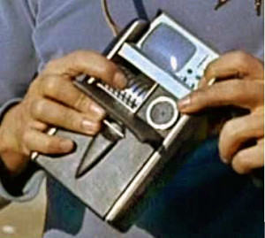
You probably remember scenes from Star Trek in which a Tricorder was used by Mr. Spock or Dr. McCoy to measure and analyze almost anything. That technology is closer than you may think.
Qualcomm is sponsoring the Tricorder XPRISE, which “is a $10 million global competition to stimulate innovation and integration of precision diagnostic technologies, helping consumers make their own reliable health diagnoses anywhere, anytime.”
Ten finalist teams have been selected. As part of the Final Round, teams will compete in both diagnostic experience evaluations and consumer testing, slated for mid-to-late 2015. The final judging and awards ceremony is scheduled to take place in early 2016.
Go to the Qualcomm Tricorder XPRISE website for details and, if you wish, sign up for their newsletter.
On 16 April 2014, Dr. Erik Viirre of the XPRISE organization spoke to the Lyncean Group about the Tricorder XPRISE. You can find more details on this talk on the Lyncean site, Past Meetings tab. Following is the direct link:
On 17 December 2014, Lambert Ninteman of San Diego State University (SDSU) spoke to Lyncean Group about their entry for the Tricorder XPRISE. You can find details on this talk and the associated presentation on the Lyncean site, Past Meetings tab. Following is the direct link:
XPRISE announced the Qualcomm Tricorder XPRIZE has been officially extended through early 2017, providing the seven finalist teams with additional time to make refine their tricorder devices to ensure they can succeed in the competition. You can read details at the following link:
A muon is an unstable elementary subatomic particle in the same class as an electron (they’re both leptons), but with a much greater mass (207 times greater). A useful property of muons is that they can penetrate matter much further than X-rays with the added benefit of causing essentially zero damage to the matter it passes through. Muons scatter and lose energy as they pass through matter, slowing down and eventually decaying, typically into three particles: an electron and two types of neutrinos. The higher the average density of the matter encountered along the muon’s flight path, the more quickly the muon slows down.
Muons are created by the interaction of high-energy cosmic rays with the upper regions of Earth’s atmosphere and they account for much of the cosmic radiation that reaches the Earth’s surface. This means that the existing flux of muon radiation at the Earth’s surface (about 10,000 muons/square meter/sec) is a free resource for clever researchers.
Muon tomography uses this free muon flux and the muon’s characteristic of slowing down more quickly in denser matter to create a density map of the field-of-view available to a muon detector. There are two types of muon imaging, transmission and scattering. The differences are addressed in LA-UR-15-24802, listed below. In both types of muon imaging, denser objects and structures in the detectors field of view appear as shadows (muon shadows) that are darker (fewer muons getting thru to the detectors) than less dense areas.
Muon tomography at the Fukushima Nuclear Power Plant
Tokyo Electric Power Company (TEPCO) supported the use of muon tomography at the Fukushima Nuclear Power Plant to help determine what damage was done to the reactor cores at Units 1, 2 and 3 during the 11 March 2011 accident, which was precipitated by a 9.0 magnitude earthquake followed by a 15-meter (49.2-ft) tsunami.
A 2013 muon tomography feasibility study (Hauro Miyadera, et al.) reported: “Muon scattering imaging has high sensitivity for detecting uranium fuel and debris even through thick concrete walls and a reactor pressure vessel. Technical demonstrations using a reactor mockup, a detector radiation test at Fukushima Daiichi, and simulation studies have been carried out. These studies establish feasibility for the reactor imaging. A few months of measurement will reveal the spatial distribution of the reactor fuel.”
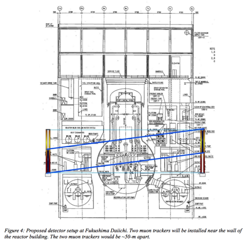
At Reactor #1, two 22 ton (20 metric ton), 21-foot by 21-foot (6.4 m by 6.4 m) muon detectors were installed and used to collect data over periods of months to develop high-resolution images of the damaged reactor core and surrounding areas. Placement of the muon detectors and the general scan geometry is shown in the following diagram.
Source: LA-UR-12-20494
Reactor #1 muon scan results
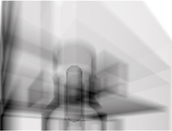
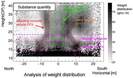
In March 2015, TEPCO announced that its muon tomography scanning efforts at Fukushima were successful, and confirmed that the nuclear plant’s Reactor #1 suffered a complete meltdown. The muon scans showed no corium (i.e., the lava-like product of a reactor core meltdown containing the melted nuclear fuel, fission products, control rods, and structural materials) remained in the reactor pressure vessel (RPV). The muon scans did not show the distribution of the corium that flowed out of the bottom of the reactor vessel into the primary containment vessel (PCV).
Muon tomography scan of Reactor #1. The corium, if present in the RPV, should have been visible as a dark shadow inside the RPV. Source: TEPCO via ExtremeTech (2015)
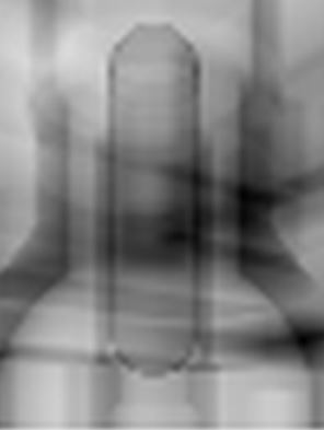
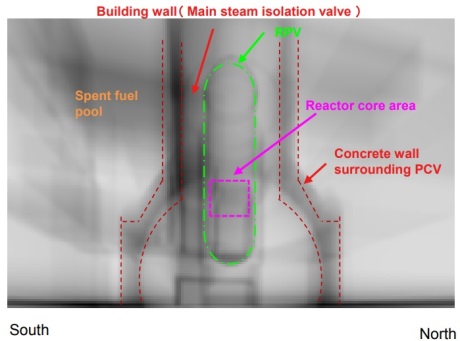
Muon tomography scan of Reactor #1, focusing on the RPV. Source: TEPCO via ExtremeTech (2015)
Reactor #2 muon scan results
World Nuclear News (WNN) reported (2016 & 2017), “TEPCO said analysis of muon examinations of the fuel debris shows that most of the fuel has melted and dropped from its original position within the core (and resolidified)…..Measurements taken between March and July 2016 at unit 2 showed high-density materials, considered to be fuel debris, in the lower area of the RPV.”
A muon tomography image of Reactor #2. Source: TEPCO via WNN (2016)
Reactor #3 muon scan results
In 2017, WNN reported, “Some of the fuel in the damaged unit 3 of the Fukushima Daiichi plant has melted and dropped into the primary containment vessel, initial results from using a muon detection system indicate. Part of the fuel, however, is believed to remain in the reactor pressure vessel.”
Muon tomography image of Reactor #3. Source: TEPCO via WNN (2017)
Summary of fuel debris status at Fukushima
Based on the results of the muon tomography program and other means of investigation, TEPCO created the following graphic summary showing the estimated distribution of core and containment vessel fuel debris in Fukushima Units 1, 2 & 3.
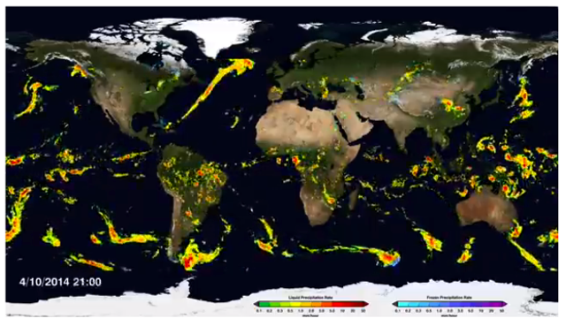
The Global Precipitation Measurement (GPM) Core Observatory – an initiative launched in 2014 as a collaboration between NASA and the Japan Aerospace Exploration Agency (JAXA) – acts as the standard to unify precipitation measurements from a network of 12 satellites. The result is NASA’s integrated multi-satellite retrievals for the GPM data product, called IMERG, which combines all of these data from 12 satellites into a single, seamless map. An example of this global map is shown below:
Check out the short article and watch a short video showing the synthesized global precipitation map in action at the following NASA link:
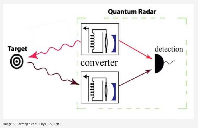
It’s also called “quantum illumination” using “entangled quantum particles”. I think I missed that class, so I found this relatively simple explanation to be helpful.
Image source: S. Barzanjeh et al., Phys. Rev. Lett.
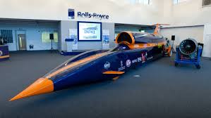
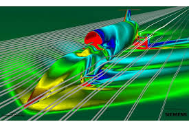
This land speed record project has gained national attention in the UK, not only for it’s ambitious goal of setting a 1,000 mph speed record on land, but also as a source of inspiration for a new generation of engineers. The “car” is propelled by a Rolls-Royce jet engine + a rocket engine.
I think you’ll find the main website for the Bloodhound Project to be well-designed and very engaging, Check it out at:
On the BLOODHOUND website, click on the “Education” tab to see how the project team is working to engage young engineers.
4 July 2016 Update: BLOODHOUND announces date for world record attempt in October 2017
On 3 July 2016, the BLOODHOUND team announced:
“We’re delighted to announce that the target date for BLOODHOUND’s 800mph world land speed record attempt in October 2017, 20 years after Thrust SSC set the existing record. Funding has been secured, with major deals recently signed, and race preparation is underway for high speed runs at the Hakskeen Pan, Northern Cape, South Africa, in Autumn next year.
BLOODHOUND SSC will travel under its own power for the first time at Newquay in June 2017, in a slow speed shakedown test at around 220mph (354km/h). This will also be an opportunity for the team to practice live-streaming data and imagery from the car.”
You can read their complete announcement at the following link:
Mark your calendar! March 18, 2015 marks the 50th anniversary of the very first extra-vehicular activity (EVA) in history, which was performed by Russian cosmonaut Alexei Leonov, who briefly left Voskhod 2 while in orbit in 1965.
This was a 12 minute spacewalk. Spacesuit over-inflation made it difficult for Leonov to re-enter the Voskhod 2 capsule and faulty hatch closure contributed to an off-course reentry.
You can read a brief article about this and other EVAs that did not go as planned at the following link:
Anyone interested in the current state of advanced nuclear reactor technology should enjoy a visit to the International Atomic Energy Agency’s ARIS website. Here’s a link to the ARIS home page:
Check out the “Publications” tab for several IAEA documents that can be downloaded as pdf files for free. I recommend one document in particular: “Status of Small and Medium Sized Reactor Designs, “ published in September 2011. This document contains 1-page summaries of 31 small and medium reactor designs from around the world, each with a small color picture. I was a bit surprised by the very large number of designs and the diverse technologies embodied in these nuclear power plants. If you’re really interested in how much small and medium reactors have advanced in the past 16 years, you can compare this 2011 document with the similar, but much more detailed, 1995 IAEA document: IAEA-TECDOC-881, “Design and Development of Small and Medium Reactor Systems 1995,” which you can download as a pdf file for free at the following link:
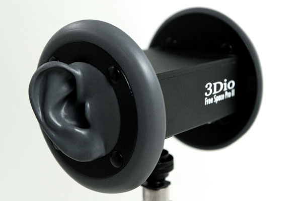
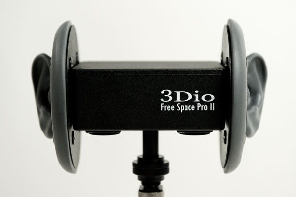
Binaural audio technology is not new, but so far, it is not common in audio systems. This technology will likely become more common as it becomes integrated in virtual reality headsets, and perhaps high-end audio recordings intended for listening with earphones. Check out the article at the following link:
In the above article, there is a link to another article that provides a more detailed description and examples for you to hear binaural audio (aka 3D audio) and compare it to conventional stereo audio. Have a set of headphones ready so you can really hear the difference. You can go directly to this article via the link below:
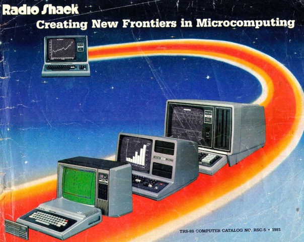
With Radio Shack in bankruptcy (again), it’s a good time for a nostalgic look at that company’s impressive product line of computers and peripheral devices before the introduction of IBM’s first personal computer (IBM 5150, introduced in August 1981) and the Apple Macintosh (introduced in a Ridley Scott TV commercial “1984”, most notably during the 3rd quarter of Super Bowl XVIII on January 22, 1984). In 1981, Radio Shack was considered by some to be the “number one microcomputer manufacturer.
1981 Radio Shack Catalog Cover
Take a trip down memory lane in Radio Shack’s 1981 TSR-80 computer catalog at the following link:
Here’s a great looking new German all-electric car that was introduced at the March 2014 Geneva Auto Show. It’s a “research” car, not for sale, but an interesting preview of a possible future application of this battery technology in production cars. The flow cell battery capacity in the e-Sportlimousine is reported to be 120 kWh. Compare this to current all-electric cars using lithium-ion battery technology: the Tesla Model S has an 85 kWh battery and a Nissan Leaf has a 24 kWh battery.
Image credit: aetherforce.com
Check out the article on the e-Sportlimousine at the following link, which includes two short videos:
A 2014 press release from NanoFLOWCELL AG describes their battery technology and it’s operational use in the e-Sportlimousine, including a description of the power train and how the car is refueled. See the following link:
Regarding the nano-network technology, Wikipedia reports: “In August 2014, the Quant e-Sportlimousine was approved for testing on public roads using the nanoFLOWCELL® system with a claimed energy or power density of 600 Wh per kilogram (per litre of salt water electrolyte).”
If you are interested in the Tesla lithium-ion battery, check out the Nov 2014, “The Tesla Battery Report”, at the following link: