All posts by Drummer

Near-Earth Object (NEO) Sky Surveys and Data Analysis are Refining our Understanding of the Risk of NEO Collisions with Earth

Peter Lobner

It seems that every week or two there is a news article about another small asteroid that soon will pass relatively close to the Earth. Most were detected while they were still approaching Earth. Some were first detected very shortly before or after their closest approach to Earth. That must have made the U.S. Planetary Defense Officer a bit nervous, but then, what could he do about it? (See my 21 January 2016 post, “Relax, the Planetary Defense Officer has the watch”).

While we currently can’t do anything to defend against NEOs, extensive worldwide programs are in place to identify and track NEOs and predict which NEOs may present a future hazard to the Earth. Here’s a brief overview of the following programs.

  • NASA Wide-field Infrared Survey Explorer (WISE)
  • International Astronomical Union’s (IAU’s) Minor Planet Center (MPC)
  • NASA’s Center for Near Earth Object Studies (CNEOS)
  • National Optical Astronomy Observatory (NOAO) NEO sky survey
  • University of Arizona Lunar and Planetary Laboratory

NASA’s Wide-field Infrared Survey Explorer (WISE)

WISE was an Earth orbiting infrared-wavelength astronomical space telescope with a 40 cm (16 in) diameter primary mirror. WISE operated from December 2009 to February 2011 and performed an “all-sky” astronomical imaging survey in the 3.4, 4.6, 12.0 and 22.0 μm wavelength bands. NASA’s home page for the WISE / NEOWISE mission is at the following link:

https://www.nasa.gov/mission_pages/neowise/mission/index.html

NEOWISE is the continuing NASA project to mine the WISE data set. An important data mining tool is the WISE Moving Object Processing System (WMOPS), which has been optimized to enable extraction of moving objects at lower signal-to-noise levels. A comet detection is shown in the following multiple images that have been combined to show the comet in four different positions relative to the fixed background stars.

Comet C/2013 A1 Siding Spring. Source: NASA/JPL-Caltech

To date, the NEOWISE data mining effort has resulted in the following:

  • Detection of ~158,000 asteroids at thermal infrared wavelengths, including ~700 near-Earth objects (NEOs) and ~34,000 new asteroids, 135 of which are NEOs.
  • Detection of more than 155 comets, including 21 new discoveries.
  • Determination of preliminary physical properties such as diameter and visible albedo for nearly all of these objects.
  • Estimation of the numbers, sizes, and orbital elements of NEOs, including potentially hazardous asteroids
  • Results have been published, enabling a range of other studies of the origins and evolution of the small bodies in our solar system.

The output from NEOWISE is delivered to NASA’s Planetary Data System (PDS), which NASA describes as follows:

“The PDS archives and distributes scientific data from NASA planetary missions, astronomical observations, and laboratory measurements. The PDS is sponsored by NASA’s Science Mission Directorate. Its purpose is to ensure the long-term usability of NASA data and to stimulate advanced research. All PDS data are publicly available and may be exported outside of United States under ‘Technology and Software Publicly Available’ (TSPA) classification.”

The link to the NASA Planetary Data System is here:

https://pds.nasa.gov

International Astronomical Union’s (IAU’s) Minor Planet Center (MPC)

The MPC describes itself as the “single worldwide location for receipt and distribution of positional measurements of minor planets, comets and other irregular natural satellites of the major planets. The MPC is responsible for the identification, designation and orbit computation for all of these objects.”

The MPC home page is here:

http://www.minorplanetcenter.net/iau/mpc.html

On this website, MPC lists the following 2017 summary statistics:
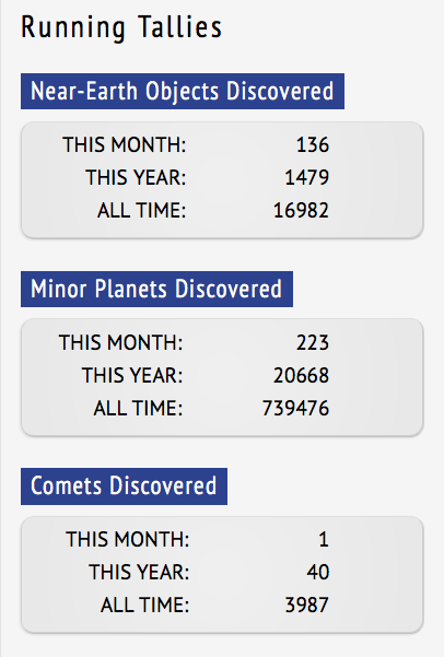
Source: MPC

The MPC website offers several short videos that explain the NEO hazard and the challenges of detecting these small objects and determining their orbital parameters with high precision. Key points made in the MPC videos include:

  • The Earth’s cross-section represents only 1/10,000th of the area of the near-Earth region. Earth is a relatively small target area for a NEO.
  • To determine if a NEO is a potential hazard, its orbital parameters must be established with a precision of greater than 1/100th of 1%.
  • There is a “zone of discoverability” (green area in the following diagram) that varies primarily by the size of the object and the aspect of its lighted side to observers on Earth. If an object is outside this rather small zone, then current sky survey instruments cannot detect the object. An example is the 15 February 2013 atmospheric blast that occurred near Chelyabinsk, Russia. This event was caused by a previously undetected NEO that approached Earth at a high relative velocity from the direction of the Sun and vaporized in the Earth’s atmosphere.

            Zone of discoverability (green area). Source: screenshot from MPC video “Asteroid Hazards, Part 2: The Challenge of Detection”

 NASA’s Center for Near Earth Object Studies (CNEOS)

CNEOS is NASA’s center for computing asteroid and comet orbits with high precision and estimating the probability of a future Earth impact. CNEOS is operated by the California Institute of Technology (Caltech) Jet Propulsion Laboratory (JPL) and supports NASA’s Planetary Defense Coordination Office.

The CNEOS home page is here:

http://cneos.jpl.nasa.gov/about/cneos.html

CNEOS is the home of JPL’s Sentry and Scout programs:

  • The Sentryimpact monitoring system performs long-term analyses of possible future orbits of hazardous asteroids, searching for impact possibilities over the next century.
  • TheScout system monitors the IAU’s MPC database for new potential asteroid discoveries and computes the possible range of future motions even before these objects have been confirmed as discoveries.

The average distance between the Earth and the moon is about 238,855 miles (384,400 km), which equals 1 LD. On the CNEOS website, you can view data on NEO close approaches to Earth at the following link:

https://cneos.jpl.nasa.gov/ca/neo_ca_intro.html

By adjusting the table settings and sorting by a specific column heading, you can create customized views of the close approach data. Just looking at data from the past year for NEOs that passed Earth within 1 LD yielded the following results:

  • 48 NEOs passed within 1 LD of Earth.
  • For these NEOs, object diameters were in the range from 1.8 to 83 meters (5.9 to 272 feet). The NEO that caused the 2013 Chelyabinsk blast was estimated to have a diameter of 10 to 20 meters (32.8 to 65.6 feet).
  • Their relative velocities were in the range from 4.02 to 23.97 km/s (8,992 to 53,620 mph). The NEO that caused the 2013 Chelyabinsk blast was estimated to have a relative velocity of 19.16 km/s (45,860 mph).
  • In the past year, the closest approach was by object 2017 GM, which had a “CA Distance Minimum” (3-signa estimate, measured from Earth center to NEO center) of 0.04 LD, or 15,376 km (9,554 miles). After subtracting Earth’s radius of 6,371 km (3,959 miles), object 2017 GM cleared the Earth’s surface by 9,005 km (5,595 miles).

Looking into the future, the CNEOS close approach data shows two objects that currently have values of “CA Distance Minimum” that are less than the radius of the Earth, indicating that impact is possible:

  • Object 2012 HG2: close approach date on 13 February 2047; modest size of 11 – 24 meters (36 – 79 feet); low relative velocity of 4.36 km/sec (9,753 mph)
  • Object 2010 RF12: close approach date of 6 September 2095; modest size of 6.4 – 14 meters (21 to 46 feet); modest relative velocity of 7.65 km/sec (17,112 mph)

So it looks like we have less than 30 years to refine the orbital data on object 2012 HG2, determine if it will impact Earth, and, if so, determine where the impact will occur and what mitigating actions can be taken. Hopefully, the U.S. Planetary Defense Officer is on top of this matter.

National Optical Astronomy Observatory (NOAO) NEO sky survey

On 30 August 2017, NOAO issued a press release summarizing the results of a survey of NEOs conducted using the Dark Energy Camera (DECam) on the 4 meter (157.5 inch) Blanco telescope at the Cerro Tololo Inter-American Observatory in northern Chile.

“Lori Allen, Director of the Kitt Peak National Observatory and the lead investigator on the study, explained, ‘There are around 3.5 million NEOs larger than 10 meters, a population ten times smaller than inferred in previous studies. About 90% of these NEOs are in the Chelyabinsk size range of 10-20 meters.’”

“David Trilling, the first author of the study,…explained…..‘If house-sized NEOs are responsible for Chelyabinsk-like events, our results seem to say that the average impact probability of a house-sized NEO is actually ten times greater than the average impact probability of a large NEO.’”

You can read the NOAO press release here:

https://www.noao.edu/news/2017/pr1704.php

You can read the draft paper, “The size distribution of Near Earth Objects larger than 10 meters,” (to be published in Astronomical Journal) here.

https://arxiv.org/pdf/1707.04066.pdf

University of Arizona Lunar and Planetary Laboratory

In October 2017, astronomer Vishnu Reddy presented data on an intriguing NEO known as 2016 HO3, that is a “quasi-satellite” of Earth. The announcement is here:

https://lbtonews.blogspot.com/2017/10/earths-new-traveling-buddy-is.html

As a “quasi-satellite,” 2016 HO3 is not gravitationally bound to Earth, but its solar orbit keeps 2016 HO3 in relatively close proximity to Earth, but in a slightly different orbital plane. As both bodies orbit the Sun, the motion of 2016 HO3 relative to the Earth gives the appearance that 2016 HO3 is in a distant halo orbit around Earth. The approximate geometry of this three body system is shown in the following diagram, with 2016 HO3’s solar orbit represented in red and the halo orbit as seen from Earth represented in yellow.

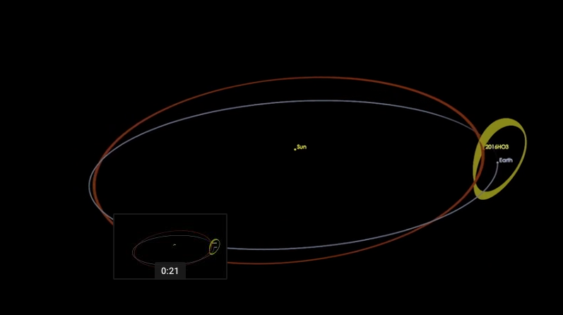
Source: www.EarthSky.org

You’ll find a video showing the dynamics of 2016 HO3’s halo orbit on the EarthSky website at the following link:

http://earthsky.org/space/near-earth-quasi-satellite-2016-ho3-confirmation?mc_cid=4d2056208e&mc_eid=19a1fde155

Observations of 2016 HO3 were made from the Large Binocular Telescope Observatory (LBTO), which is located on Mt. Graham in Arizona. You’ll find details on LBTO at the following link:

http://www.lbto.org/overview.html

Key parameters for 2016 HO3 are: diameter: 100 meters (330 feet); distance from Earth: 38 to 100 LD; composition appears to be the same material as other asteroid NEOs. With its stable halo orbit, there is no risk that 2016 HO3 will collide with Earth.

For additional reading on NEO discovery:

Myhrvold, “Comparing NEO Search Telescopes,” Astronomical Society of the Pacific, April 2016

Abstract:

“I use simple physical principles to estimate basic performance metrics for the ground-based Large Synoptic Survey Telescope and three space-based instruments— Sentinel, NEOCam, and a Cubesat constellation.”

http://iopscience.iop.org/article/10.1088/1538-3873/128/962/045004/pdf

S.R. Chesley & P. Vereš, “Projected Near-Earth Object Discovery Performance of the Large Synoptic Survey Telescope,” JPL Publication 16-11, CNEOS, April 2017

Abstract:

“LSST is designed for rapid, wide-field, faint surveying of the night sky ….The baseline LSST survey approach is designed to make two visits to a given field in a given night, leading to two possible NEO detections per night. These nightly pairs must be linked across nights to derive orbits of moving objects…… Our simulations revealed that in 10 years LSST would catalog 60% of NEOs with absolute magnitude H < 22, which is a proxy for 140 m and larger objects.”

https://cneos.jpl.nasa.gov/doc/JPL_Pub_16-11_LSST_NEO.pdf

60th Anniversary of Sputnik 1, the World’s First Man-made Earth-orbiting Satellite

Peter Lobner

4 October 1957 was a major milestone in aerospace history, marking the first launch of an artificial satellite into Earth orbit.  Since 1955, a relatively low-key “space race” between the U.S. and the Soviet Union had been underway, with the U.S. openly developing the small Vanguard booster rocket and satellite and planning to launch the first satellite into orbit during the International Geophysical Year (1 July 1957 to 31 December 1958).  Secrecy surrounding the Soviet Union’s space program made the successful launch of Sputnik 1 a significant political coup.  This event served to greatly energized the lagging U.S. space program and prompted calls for more technical education in the U.S.

Source:  The New York Tines

The small spherical Sputnik 1 satellite had a diameter of 23 inches (58 cm) and a weight of 184 pounds (83.6 kg).  Functionally, Sputnik 1 was very simple, consisting of a battery power supply, a radio transmitter, a thermal control system and a remote control switch housed within the nitrogen-pressurized sphere. You’ll find a description of how Sputnik 1 worked at the following link:

http://www.popularmechanics.com/space/satellites/news/a28496/how-sputnik-worked/

The satellite transmitted a continuous “beep-beep-beep…” on two frequencies until 28 October 1957, when it went silent.

The four whip antennae provided a spherical radiation pattern for the broadcast radio signals.  Source:  Smithsonian Air and Space Museum

Sputnik 1 interior arrangement. The silver-zinc batteries were in the hexagonal enclosure.  The radio transmitters were in the center of that hexagon.  Source: Space.com

Sputnik 1’s low Earth orbit decayed over the next three months and the satellite reentered the Earth’s atmosphere and was destroyed on 4 January 1958, after about 1,400 orbits.

Sputnik 1 was launched by an R-7 liquid-fueled booster rocket, which was a version of the Soviet Union’s first intercontinental ballistic missile (ICBM), the SS-6.  The R-7 booster rocket, which consisted of a liquid-fueled core stage surrounded by four liquid-fueled strap-on boosters, was developed by the design bureau headed by Sergei Pavlovitch Korolev (1906-1966). The strap-on boosters separated about 116 seconds after launch.  The core stage achieved orbit along with the Sputnik 1 satellite and the payload fairing.  The core stage reentered the atmosphere in December 1957.

R-7 booster.  Source: Space.com

The R-7 booster evolved into the launch vehicle for future Soviet Vostok, Voskhod and Soyuz missions, and a version continues in use today as the Russian launch vehicle taking astronauts and supplies to the International Space Station (ISS) aboard updated Soyuz spacecraft.

Evolution of the R-7 booster.  Source:  NASA  / Peter Gorin / Emmanuel Dissais

The R-7 booster launched the larger Sputnik 2 satellite into earth orbit on 3 November 1957, before any satellite launch attempt by the U.S.  Sputnik 2 carried the first living thing into orbit, the “space dog” named Laika. The even larger Sputnik 3 was launched on 15 May 1958.  These first three Sputnik launches had lasting effects on the civilian space race and the military missile race between the U.S. and the Soviet Union.

The U.S. civilian Earth Satellite Program (aka Project Vanguard) favored by President Dwight Eisenhower, planned to launch the first U.S. earth-orbiting satellite during the International Geophysical Year (IGY, 1 July 1957 – 31 December 1958) using a Vanguard rocket being developed by Naval Research Laboratory (NRL).  Vanguard was quickly eclipsed by the Army Ballistic Missile Agency’s satellite program, which was hastily mobilized after the Sputnik 1 launch. The Army – Jet Propulsion Laboratory (JPL) team, led by Dr. Werner von Braun (Army) and Dr. William Pickering (JPL), was successful on their first attempt and placed the first U.S. satellite, Explorer I, in orbit on 31 January 1958.  After two launch failures, the first Vanguard satellite reached orbit on 17 March 1958.

Thereafter, the Soviet – U.S. space race was a focus of national and international attention, with President John F. Kennedy setting a seemingly optimistic national goal in 1961: “…before this decade is out, of landing a man on the Moon and returning him safely to the Earth….”  The U.S. Apollo 11 mission met this goal when the astronauts Neil Armstrong and Edwin “Buzz” Aldrin, Jr. landed on the Moon on 20 July 1969, just 12 years after Sputnik 1 first reached earth orbit.

Sputnik 1 60thanniversary artwork.Source:  http://photobucket.com/gallery/user/fontman1962/media/

Update 24 September 2018:

This post was updated with additional content.

Remote Sensing Shows the Extent of Flooding from Hurricane Harvey and Other Large Flooding Events

Peter Lobner

Dartmouth Flood Observatory, at the University of Colorado, Boulder, CO, integrates international satellite data to develop a worldwide view of surface water issues, and can provide regional maps that show the extent of flooding in areas of interest. Data from many satellite sources are used, including NASA’s MODIS (Moderate Resolution Imaging Spectrometer) and Landsat, European Space Agency’s (ESA) Sentinel 1, ASI (Agenzia Spaziale Italiana) Cosmos-SkyMed, and Canadian Space Agency’s Radarsat 2.

The Dartmouth Flood Observatory homepage is here:

http://floodobservatory.colorado.edu

The world view of large flooding events as of 26 August 2017 is shown in the graphic.

Source: Dartmouth Flood Observatory

The following 31 August 2017 maps show the areas in Texas and Louisiana that were flooded by Hurricane Harvey also known as DFO flood event 4510). Red represents flooded areas, blue represents normal water extent, and dark grey represents urban areas.

Area mapSource: Dartmouth Flood Observatory

Here’s the link to these detailed flooding maps for Hurricane Harvey:

http://floodobservatory.colorado.edu/Events/2017USA4510/2017USA4510.html

This webpage also provides links to other information sources related to Hurricane Harvey.

The Dartmouth Flood Observatory maintains an archive of large flood events from 1985 to present. This archive is accessible online at the following link:

http://floodobservatory.colorado.edu/Archives/index.html

Dartmouth Flood Observatory is a member of the Global Flood Partnership (GFP), which describes itself as, “a cooperation framework between scientific organizations and flood disaster managers worldwide to develop flood observational and modeling infrastructure, leveraging on existing initiatives for better predicting and managing flood disaster impacts and flood risk globally.” For more information on the Global Flood Partnership, visit their homepage and portal at the following links:

https://gfp.jrc.ec.europa.eu/about-us

http://portal.gdacs.org/Global-Flood-Partnership

The Importance of Baseload Generation and Real-Time Control to Grid Stability and Reliability

Peter Lobner

On 23 August 2017, the Department of Energy (DOE) issued a report entitled, “Staff Report to the Secretary on Energy Markets and Reliability.” In his cover letter, Energy Secretary Rick Perry notes:

“It is apparent that in today’s competitive markets certain regulations and subsidies are having a large impact on the functioning of markets, and thereby challenging our power generation mix. It is important for policy makers to consider their intended and unintended effects.”

Among the consequences of the national push to implement new generation capacity from variable renewable energy (VRE) resources (i.e., wind & solar) are: (1) increasing grid perturbations due to the variability of the output from VRE generators, and (2) early retirement of many baseload generating plants because of several factors, including the desire of many states to meet their energy demand with a generating portfolio containing a greater percentage of VRE generators. Grid perturbations can challenge the reliability of the U.S. bulk power systems that comprise our national electrical grid. The reduction of baseload capacity reduces the resilience of the bulk power system and its ability dampen these perturbations.

The DOE staff report contains the following typical daily load curve. Baseload plants include nuclear and coal that operate at high capacity factor and generally do not maneuver in response to a change in demand. The intermediate load is supplied by a mix of generators, including VRE generators, which typically operate at relatively low capacity factors. The peak load generators typically are natural gas power plants that can maneuver or be cycled (i.e., on / off) as needed to meet short-term load demand. The operating reserve is delivered by a combination of power plants that can be reliably dispatched if needed.

The trends in new generation additions and old generation retirements is summarized in the following graphic from the DOE staff report.

Here you can see that recent additions (since 2006) have focused on VRE generators (wind and solar) plus some new natural gas generators. In that same period, retirements have focused on oil, coal and nuclear generators, which likely were baseload generators.

The DOE staff report noted that continued closure of baseload plants puts areas of the country at greater risk of power outages. It offered a list of policy recommendations to reverse the trend, including providing power pricing advantages for baseload plants to continue operating, and speeding up and reducing costs for permitting for baseload power and transmission projects.

Regarding energy storage, the DOE staff report states the following in Section 4.1.3:

“Energy storage will be critical in the future if higher levels of VRE are deployed on the grid and require additional balancing of energy supply and demand in real time.”

“DOE has been investing in energy storage technology development for two decades, and major private investment is now active in commercializing and the beginnings of early deployment of grid-level storage, including within microgrids.”

Options for energy storage are identified in the DOE staff report.

You can download the DOE staff report to the Secretary and Secretary Perry’s cover letter here:

https://energy.gov/downloads/download-staff-report-secretary-electricity-markets-and-reliability

Lyncean members should recall our 2 August 2017 meeting and the presentation by Patrick Lee entitled, “A fast, flexible & coordinated control technology for the electric grid of the future.” This presentation described work by Sempra Energy and its subsidiary company PXiSE Energy Solutions to address the challenges to grid stability caused by VRE generators.   An effective solution has been demonstrated by adding energy storage and managing the combined output of the VER generators and the energy storage devices in real-time to match supply and demand and help stabilize the grid. This integrated solution, with energy storage plus real-time automated controls, appears to be broadly applicable to VRE generators and offers the promise, especially in Hawaii and California, for resilient and reliable electrical grids even with a high percentage of VRE generators in the state’s generation portfolio.

You can download Patrick Lee’s 2 August 2017 presentation to the Lyncean Group of San Diego at the following link:

https://lynceans.org/talk-113-8217/

Return of the Stellarator

Updated 19 March 2020

Peter Lobner

Background

Dr. Lyman Spitzer invented the stellarator in 1951 and built several versions of this magnetic plasma confinement machine at Princeton University during the 1950s and 1960s, establishing the world famous Princeton Plasma Physics Laboratory (PPPL) in the process. Dr. Spitzer’s earliest Stellarators were figure-eight devices as shown in the following photo.

Example of an early stellarator at the 1958 Atoms for Peace Conference, Geneva

In these first-generation stellarators, field coils wrapped around the figure-eight vacuum vessel provided the basic plasma confinement field. The physical twist in the stellarator’s structure twisted the internal magnetic confinement field and cancelled the effects of plasma ion drift during each full circuit around the device. You can download Dr. Spitzer’s historic 1958 IAEA conference paper, “The Stellarator Concept,” at the following link:

http://www-naweb.iaea.org/napc/physics/2ndgenconf/data/Proceedings%201958/papers%20Vol32/Paper23_Vol32.pdf

The next generation of stellarators adopted a simpler torus shape and created the twist in the magnetic confinement field with helical field coils outside the vacuum vessel.

While stellarators achieved many important milestones in magnetic confinement, by the late 1960s, the attention of the fusion community was shifting toward a different type of magnetic confinement machine: the tokamak. Since then, this basic design concept has been employed in many of the world’s major fusion devices, including the Alcator-C Mod (MIT, USA), Doublet III-D (DIII-D at General Atomics, USA), Tokamak Fusion Test Reactor (TFTR at PPPL, USA), Joint European Torus (JET, UK), National Spherical Torus Experiment Upgrade (NSTX-U at PPPL, USA) and the International Thermonuclear Experimental Reactor (ITER, France).

Now, almost 50 years later, there is significant renewed interest in stellarators. The newest device, the Wendelstein 7-X stellarator, became operational in 2016. It may help determine if modern technology has succeeded in making the stellarator a more promising path to fusion power than the tokamak.

Comparison of Tokamaks and Stellarators

Modern tokamaks and stellarators both implement plasma confinement within a (more or less) toroidal vacuum vessel that operates at very high vacuum conditions, on the order of 10-7 torr. Both types of machines use the combined effects of two or more magnetic fields to create and control helical field lines (HFL) that enable plasma confinement and reduce particle drift in the circulating plasma.

In the following description, the simple “classical” tokamak configuration shown below will be the point of reference.

Source: Hans-Jürgen Hartfuß, Thomas Geist, “Fusion Plasma Diagnostics With mm-Waves: An Introduction”

The main features of a tokamak are summarized below.

  • The vacuum vessel in a modern tokamak typically is an azimuthally-symmetric torus of revolution (donut-shaped), typically with a vertically elongated, D-shaped cross section. Modern “spherical” tokomaks maintain the D-shaped cross section, but minimize the diameter of the hole in the center of the torus.
  • Plasma confinement within the vacuum vessel is accomplished by the combined effects of a toroidal magnetic field and an induced poloidal magnetic field. Together, these fields create the helical field lines for plasma confinement. In the following diagram, the toroidal field is represented by the blue arrow and the poloidal field is represented by the red arrow.

By Dave Burke – Own work, CC BY 2.5, https://commons.wikimedia.org/w/index.php?curid=1169843

  • The toroidal field (blue) is generated by a set of external toroidal field coils (TFCs) that surround the vacuum vessel.
  • The poloidal field (red) is generated by a strong induced plasma current (Iplasma), on the order of 106 amperes, flowing within the plasma inside the vacuum vessel. An external coil in the center of the tokamak serves as the primary coil of a transformer and the circulating plasma serves as the secondary coil of the transformer. To create the poloidal field, the transformer primary coil is charged at a controlled rate (i.e. to yield the desired rate of flux increase), thereby inducing a current in the plasma and heating the plasma by ohmic heating. When the primary coil reaches maximum flux, current is no longer induced in the plasma and the tokamak “pulse” is over.
  • A pair of vertical field coils (VFC), one above and one below the plane of the torus, provide the ability to radially position the plasma within the vacuum vessel.
  • Divertors inside the vacuum vessel define the maximum extent of the magnetically confined plasma, remove impurities from the edge of the plasma, and help minimize plasma-wall interactions.
  • The high current in the plasma can falter unexpectedly, resulting in a “disruption”, which is a sudden losses of plasma confinement that can unleash magnetic forces powerful enough to damage the machine.
  • A tokamak is mechanically simpler than a stellarator.
  • The physics characteristics of a tokamak typically yield better confinement capabilities than a stellarator.
  • While the “pulse” in a modern tokamak can last several tens of minutes, a pulsed mode of operation may not be suitable for a commercial fusion reactor.
  • Pulsed magnetic and thermal loads create mechanical fatigue issues that must be accommodated in the design of tokamak structures.

The simple “classical” stellarator configuration shown below will be the point of reference for the following discussion.

Source: Hans-Jürgen Hartfuß, Thomas Geist, “Fusion Plasma Diagnostics With mm-Waves: An Introduction”

The main features of a stellarator are summarized below.

  • There are many variants of devices called stellarators, with names such as Torsatron, Heliotron, Heliac, and Helias. All create the plasma confinement field with external magnet systems in various configurations and none depend on the existence of a toroidal plasma current.
  • In the classical stellarator in the above diagram, the plasma confinement field is created by a set of planar (flat) TFCs and external pairs (1, 2 or 3) of twisting helical field coils (HFC) with opposite currents in each conductor in the pair.
  • A stellarator is mechanically more complex and more difficult to manufacture than a tokamak.
  • Stellarators may use a divertor or a simpler “limiter” to define the outer extent of the plasma.
  • While a stellarator has no induced plasma current, other small currents, known as “pressure-driven” or “bootstrap” currents, exist. These small currents do not cause plasma disruptions as may occur in a tokamak, but complicate plasma confinement.
  • A stellarator is intrinsically capable of steady-state operation.
  • For a variety of reasons, a classical stellarator tends to lose energy at a higher rate than a tokamak. Advanced, modular stellarators are making progress in improving confinement performance.

You’ll find more comparative information in the July 2016 paper by Y. XU, “A general comparison between tokamak and stellarator plasmas,” which is available at the following link:

http://ac.els-cdn.com/S2468080X16300322/1-s2.0-S2468080X16300322-main.pdf?_tid=7d9ff748-c680-11e6-9909-00000aacb35d&acdnat=1482216764_912e05c8d6b4957207a2e7ae31c30f03

Modern stellarators

In the last two decades, dramatic improvements in computer power and 3-dimensional modeling capabilities have enabled researchers and designers to accurately model a stellarator’s complex magnetic fields, plasma behavior, and mechanical components (i.e., vacuum vessel, magnet systems and other structures). This has enabled implementation of a “plasma first” design process in which the initial design focus is on optimizing plasma equilibrium based on selected physics conditions. Key goals of this optimization process are to define plasma equilibrium conditions that reduce heat transport and particle loss from the plasma. As you might suspect, there are different technical bases for approaching the plasma optimization process. The stellarator’s magnet systems are designed to produce the confinement field needed for the specified, optimized plasma design.

This class of modern, optimized stellarators is characterized by complex, twisting plasma shapes and non-planar, modular toroidal coils that are individually designed, built and assembled. The net result is a stellarator with significantly better confinement performance that earlier stellarator designs. In this post, we’ll look in more detail at the following three advanced stellarators:

  • Wendelstein 7-AS [Max Planck Institute for Plasma Physics (IPP), Garching, Germany]
  • Helically Symmetric eXperiment (HSX, University of Wisconsin – Madison, USA)
  • Wendelstein 7-X [Max Planck Institute for Plasma Physics (IPP), Griefswald, Germany]

 Wendelstein 7-AS Stellarator (1988 – 2002)

The Wendelstein 7-AS (W7-AS) was the first modular, advanced stellarator and was the first stellarator equipped with a divertor. It was used to test and validate basic elements of stellarator optimization.  Basic physical parameters of W7-AS are:

  • Major radius 2 m
  • Minor radius 0.2 m
  • Magnetic field 2.5 – 3 T

The physical layout and scale of the W7-AS machine is shown in the first diagram, below, with more details on the magnet system in the following diagram.

Above & below: Wendelstein 7-AS. Source: Max Planck IPP, I. Weber

The W7-AS operated from 1988 to 2002.   The IPP reported the following results:

  • Demonstrated that the innovative modular magnet coil system can be manufactured to exacting specifications.
  • Demonstrated improved plasma equilibrium and transport behavior because of the improved magnetic field structure.
  • Confirmed the effectiveness of the optimization criteria.
  • Demonstrated the effectiveness of a divertor on a stellarator (a common feature in tokamaks).

You’ll find more details on the W7-AS on the IPP website at the following link:

http://www.ipp.mpg.de/2665443/w7as?page=1

Its successor is the Wendelstein 7-X.

Helically Symmetric eXperiment (HSX)

HSX is a small modular coil advanced stellarator that began operation in 1999 at the Electrical and Computer Engineering Department at the University of Wisconsin-Madison. HSX basic design parameters are:

  • Major radius 1.2 m
  • Minor radius 0.15 m
  • Magnetic field 1T

The physical arrangement of HSX is shown in the following diagram.

HSX physical configuration. Source: University of Wisconsin – Madison

The HSX was the first stellarator to be optimized to deliver a “quasi-symmetric” magnetic field. While the magnetic field strength is usually a two-dimensional function on the magnetic surfaces traced out by the field lines, quasi-symmetry is achieved by making it one-dimensional in so-called “magnetic coordinates” (Boozer coordinates).

Author Masayuki Yokoyama’s paper, “Quasi-symmetry Concepts in Helical Systems,” provides a description of quasi-symmetry.

“A key point of quasi-symmetry is that the drift trajectories of charged particles depend on the absolute value of the magnetic field (B) expressed in terms of magnetic field coordinates (Boozer coordinates). The plasma can be optimized in terms of the Boozer coordinates instead of the vector components of the field.”

You can read Yokoyama’s complete paper at the following link:

https://www.jstage.jst.go.jp/article/jspf/78/3/78_3_205/_pdf

The HSX main magnetic field is generated by a set of 48 non-planar, modular coils, arranged in four field periods, yielding the twisting flux shape shown below.


HSX plasma configuration. Source: University of Wisconsin – Madison

The HSX team reported that “this is the first demonstration that quasi-symmetry works, and you can actually measure the reduction in transport that you get.”

The home page for this project is at the following link:

http://www.hsx.wisc.edu

You can download a description of the HSX here:

http://www.hsx.wisc.edu/wp-uploads/2016/04/A-helically-symmetric-stellarator-HSX_Almagri_Anderson-DT_Anderson-FSB_Probert_Shohet_Talmadge_1999.pdf

 Wendelstein 7-X Stellarator

The Wendelstein 7-X (W7-X) is a Helias (helical advanced stellarator) and is the first large-scale optimized stellarator; significantly larger than Wendelstein 7-AS and HSX. The complete W7-X machine weighs about 750 tons, with about 425 tons operating under cryogenic conditions. The superconducting magnet system is designed for steady-state, high-power operation; nominally 30 minutes of plasma operation at 10 MW power. W7-X basic design parameters are:

  • Major radius 5.5m
  • Minor radius 0.52m
  • Magnetic field 2.5 T (up to 3T)

The IPP home page for this project is here:

http://www.ipp.mpg.de/w7x

The W7-X is drift optimized for improved thermal and fast ion confinement by: (a) implementing quasi-symmetry to reduce transport losses, (b) minimizing plasma currents (Pfirsch-Schluter & bootstrap currents) to improve equilibrium, and (c) designing a large magnetic well in the plasma cross-section to avoid plasma pressure instabilities.

The primary purpose of the Wendelstein 7-X is to investigate the new stellarator’s suitability for extrapolation to a fusion power plant design. The IPP website provides the following clarification:

“It is expected that plasma equilibrium and confinement will be of a quality comparable to that of a tokamak of the same size. But it will avoid the disadvantages of a large current flowing in a tokamak plasma: With plasma discharges lasting up to 30 minutes, Wendelstein 7-X is to demonstrate the essential stellarator property, viz. continuous operation.”

The main assembly of Wendelstein 7-X was completed in 2014. An IPP presentation on the manufacturing and assembly of W7-X is at the following link:

https://www.iter.org/doc/www/content/com/Lists/Stories/Attachments/680/ITER_W7X.pdf

You’ll also find a good video, “Wendelstein 7-X — from concept to reality,” which provides an overview of the design and construction of the W7-X stellarator and the associated research facility, at the following link:

https://www.youtube.com/watch?v=lyqt6u5_sHA

After engineering tests, the first plasma was produced at W7-X on 10 December 2015. A November 2016 article in Nature summarized on the results of initial operation of W7-X.  The article, entitled, “Confirmation of the topology of the Wendelstein 7-X magnetic field to better than 1:100,000,” confirmed that the W7-X is producing the intended confinement field. This article includes the following 3-D rendering and description of the complex magnetic coil sets that establish the twisting plasma confinement fields in the W7-X.

“Some representative nested magnetic surfaces are shown in different colors in this computer-aided design (CAD) rendering, together with a magnetic field line that lies on the green surface. The coil sets that create the magnetic surfaces are also shown, planar coils in brown, non-planar coils in grey. Some coils are left out of the rendering, allowing for a view of the nested surfaces (left) and a Poincaré section of the shown surfaces (right). Four out of the five external trim coils are shown in yellow. The fifth coil, which is not shown, would appear at the front of the rendering.”

You can read the complete article at the following link:

http://www.nature.com/articles/ncomms13493

A more detailed mechanical view of the W7-X, with a scale (gold) human figure is shown in the following diagram:

Source: IPP presentation, “Stellarators difficult to build? The construction of Wendelstein 7-X”

The large scale of the W7-X vacuum vessel is even more apparent in the following photo.

A segment of W7-X vacuum vessel.  Source: adapted from IPP by C. Bickel and A. Cuadra/Science

Most of the wall protection components are uncooled. Operational limits on the W7-X (i.e., pulse duration, various temperatures) help protect the integrity of wall components.

The status of the W7-X as of February 2017 is outlined in a presentation by the W7-X team to the Fusion Energy Science Advisory Committee (FESAC), entitled “Recent results and near-term plans for Wendelstein 7-X,” which is available at the following link:

http://www.firefusionpower.org/FESAC_W7-X_Pedersen_02.2017.pdf

Update 19 March 2020:  Proof of principal and a new upgrade campaign

 In February 2020, Princeton Plasma Physics Laboratory (PPPL) reported on the SciTechDaily website that W7-X operation through the end of 2018 had successfully demonstrated the expected capability to moderate plasma leakage and improve plasma confinement.  W7-X operation had achieved hundred-second pulses with heating powers of two megawatts and plasma energies of 200 megajoules.  PPPL physicist Novimir Pablant stated, “This research validates predictions for how well the optimized design of the W7-X reduces neoclassical transport….,” and, “The research marks the first step in showing that high-performance stellarator designs such as W-7X are an attractive way to produce a clean and safe fusion reactor.”

You’ll find the PPPL report here:  https://scitechdaily.com/cutting-edge-w7-x-nuclear-fusion-device-overcomes-obstacles/

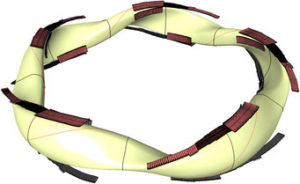
Wide angle view of the interior of the Wendelstein 7-X plasma vessel, showing the different armor materials designed to take up the heat from the plasma. The surface contour of the wall follows the shape of the plasma. On average, the radius of the plasma is 55 cm. Credit: Bernhard Ludewig, Max Planck Institute of Plasma Physics

At the end of 2018, operation of the W7-X ceased and a new round of modifications was started.  Key upgrades being implemented now for the W7-X are:

  • Installation of new water-cooled inner cladding on large sections of the plasma vessel to enable the W7-X to handle higher heating loads and longer plasma pulses, up to 30 minutes.
  • Installation of ten double strip, water-cooled divertor plates on the inner wall of the plasma vessel. Divertors are the parts of the new cladding system used to regulate the interaction between plasma and the inner wall of the plasma vessel.  Without water cooling, the heat-resistant divertor tiles made of carbon-fiber-reinforced carbon could not withstand the heat load for the intended 30-minute plasma pulses.

In ten curved double strips, the divertor plates (brown) follow the shape of the twisted plasma (yellow).  Source: IPP

IPP reports that this upgrade work is expected to continue until the end of 2021.  You’ll find more details on the upgrade work, including the design of the divertors, on the IPP website at the following link:  https://www.ipp.mpg.de/4828222/01_20

Conclusion

Following the success of two Wendelstein 7-X experimental campaigns from March 2016 to October 2018, a promising path forward is being pursued by the Max Planck Institute for Plasma Physics.  Nonetheless, I believe my previous conclusion (below, from the original post in 2017) still stands.  We’ll know a lot more after the W7-X upgrade work is completed and operations resume in late 2021.

So the jury is still out on the ability of advanced, optimized stellarators to take the lead over tokamaks in the long, hard journey toward the goal of delivering usable power from a fusion machine.  Hopefully, the advanced stellarators will move the fusion community closer to that goal.  No doubt, we still have a very long way to go before fusion power becomes a reality.

For more background information on stellarators:

A summary of Dr. Spitzer’s pioneering work at PPPL is documented in the following presentation:

There are good briefings on the basics of stellarator design and operation in the following two documents:

Manufacturing the Reactor Vessel for an RITM-200 PWR for Russia’s new LK-60 Class of Polar Icebreakers

Peter Lobner

The first ship in the new LK-60 class of nuclear powered icebreakers, named Arktika, was launched on 16 June 2016 at the Baltic Shipyard in St. Petersburg, Russia. LK-60 class icebreakers are powered by two RITM-200 integral pressurized water reactors (PWR), each rated at 175 MWt, and together delivering 60 MW (80,460 hp) to an electric motor propulsion system driving three shafts.

LK-60 class icebreakers are the most powerful icebreakers in the world. Contracts for two additional LK-60 icebreakers were placed in May 2014. They are scheduled for delivery in 2020 (Sibr) & 2021 (Ural).

The general arrangement of the nuclear reactors in these ships is shown in the following two diagrams.

Two RITM-200 reactors installed on an LK-60 class icebreaker. Source: Atomenergomash

The basic design of the RITM-200 integral primary system is shown in the following diagram. The reactor and steam generators are in the same vessel. The four primary pumps are connected directly to the reactor vessel, creating a very compact primary system unit.

The two reactor vessels were installed in Arktika in September 2016, which is scheduled to be service-ready in mid-2019, and will operate from the Atomflot icebreaker port in Murmansk. Manufacturing of the reactor vessels for the second LK-60 icebreaker, Sibr, is in progress.

Above: Second integral reactor vessel for Arktika, with the primary pump housings installed. Source: Rosatom

Below: Integral reactor vessel at an earlier stage of manufacturing for Sibr.  Source: Atomenergomash

Below: Complete RITM-200 integral reactor vessel. Source: Atomenergomash

You can watch an Atomenergomash video (in Russian) showing how the RITM-200 reactor vessel is manufactured at the following link:

The U.S. has no nuclear powered icebreakers and only one, older polar-class icebreaker. See my 3 September 2015, “The Sad State of Affairs of the U.S. Icebreaking Fleet and Implications for Future U.S. Arctic Operations,” for more information on the U.S. icebreaker fleet.

Preliminary Design of an Experimental World-Circling Spaceship

Peter Lobner

The title of this post also is the title of the first RAND report, SM-11827, which was issued on 5 May 1946 when Project RAND still was part of the Douglas Aircraft Company. The basic concept for an oxygen-alcohol fueled multi-stage world-circling spaceship is shown below.

Source: RAND

Source: RAND

Now, more than 70 years later, it’s very interesting to read this report to gain an appreciation of the state of the art of rocketry in the U.S. in 1946, which already was benefiting from German experience with the V-2 and other rocket programs during WW II.

RAND offers the following abstract for SM-11827:

“More than eleven years before the orbiting of Sputnik, history’s first artificial space satellite, Project RAND — then active within Douglas Aircraft Company’s Engineering Division — released its first report: Preliminary Design of an Experimental World-Circling Spaceship (SM-11827), May 2, 1946. Interest in the feasibility of space satellites had surfaced somewhat earlier in a Navy proposal for an interservice space program (March 1946). Major General Curtis E. LeMay, then Deputy Chief of the Air Staff for Research and Development, considered space operations to be an extension of air operations. He tasked Project RAND to undertake a feasibility study of its own with a three-week deadline. The resulting report arrived two days before a critical review of the subject with the Navy. The central argument turns on the feasibility of such a space vehicle from an engineering standpoint, but alongside the curves and tabulations are visionary statements, such as that by Louis Ridenour on the significance of satellites to man’s store of knowledge, and that of Francis Clauser on the possibility of man in space. But the most riveting observation, one that deserves an honored place in the Central Premonitions Registry, was made by one of the contributors, Jimmy Lipp (head of Project RAND’s Missile Division), in a follow-on paper nine months later: ‘Since mastery of the elements is a reliable index of material progress, the nation which first makes significant achievements in space travel will be acknowledged as the world leader in both military and scientific techniques. To visualize the impact on the world, one can imagine the consternation and admiration that would be felt here if the United States were to discover suddenly that some other nation had already put up a successful satellite.’”

You can buy the book from several on-line sellers or directly from RAND. However you also can download the complete report for free in three pdf files that you’ll find on the RAND website at the following link:

https://www.rand.org/pubs/special_memoranda/SM11827.html

Qualcomm Tricorder XPrize Winners Announced

Peter Lobner

In my 24 December 2016 post, I reported that the Qualcomm Tricorder XPrize committee had selected two teams to continue into the finals: Dynamical Biomarkers Group and Final Frontier Medical Devices.   On 12 April 2017, the Qualcomm Tricorder XPrize committee announced the winners…and yes, there were two winners:

“Of the 300 teams that joined the pursuit of the Qualcomm Tricorder XPRIZE, Final Frontier Medical Devices and Dynamical Biomarkers Group were both announced winners at the Qualcomm Tricorder XPRIZE awards ceremony on April 12, 2017.

Final Frontier Medical Devices was announced the highest performing team and received $2.5M for their achievement and Dynamical Biomarkers Group received $1M for 2nd place. Both teams exceeded the competition requirements for user experience, nearly met the challenging audacious benchmarks for diagnosing the 13 disease states, and with their prototypes, have taken humanity one step closer to realizing Gene Roddenberry’s 23rd century sci-fi vision. XPRIZE congratulates Final Frontier Medical Devices and Dynamical Biomarkers Group on their amazing achievements.”

Learn more about Final Frontier Medical Devices and their winning tricorder named DxtER here:

http://tricorder.xprize.org/teams/final-frontier-medical-devices

Learn more about Dynamical Biomarkers Group and their 2nd place tricorder system comprised of three modules here:

http://tricorder.xprize.org/teams/dynamical-biomarkers-group

OK, neither XPrize tricorder prototype looks like Dr. McCoy’s hand-held tricorder seen on Star Trek (the original series), but the automated diagnostic capabilities offered by the XPrize tricorder prototypes really are a giant leap forward in the development of tricorder technology for the real world. The Qualcomm Tricorder XPrize competition has been successful in making this happen on an accelerated schedule.

McCoy and his tricorder. Source: Star Trek (the original series), Desilu Productions

Star Trek Tricorder replica. Source: Amazon.com

56 Years Ago: Yuri Gagarin Became the First Person in Space

Peter Lobner

On 12 April 1961, the Soviet Union launched the Vostok 1 (“East” 1) spacecraft and astronaut Major Yuri Gagarin from a launch site in Kazakhstan on the first ever manned space mission. Gagarin became the first person to fly above the Karman line that marks the beginning of space, at 62 miles (330,000 feet, 100 km) above the Earth. He also became the first person to achieve Earth orbit.

Yuri Gagarin. Source: Daily Mail

Basic orbital parameters for Vostok 1 were: apogee: 203 miles (327 km), perigee: 117 miles (189 km), and orbital period: 89.1 minutes. Gagarin completed one orbit. After re-entry, Gagarin ejected from the Vostok capsule at an altitude of about 4.3 miles (7 km) and parachuted to the ground. The capsule descended under its own parachute and was recovered near Engels, Russia. Gagarin’s total flight time was 1 hour, 48 minutes.

The path of Gagarin’s historic flight, including important flight milestones, is shown on the following map:

Source: http://space.stackexchange.com/

The configuration of the Vostok spacecraft is shown in the following diagram. The reentry vehicle is the spherical capsule, which on the left is shown attached to the instrument module.

Vostok 1 configuration.  Source: Pinterest

The complete spacecraft had a mass of 4.73 tons (4,300 kg) and measured 14.4 feet (4.4 meters) in length and 8 feet (2.43 meters) in diameter. The placement of the spacecraft inside the nose shroud of the launch vehicle is shown in the following diagram.

Source: http://www.rocketryforum.com/showthread.php?49802-Dr-Zooch-Vostok-build-thread

Yuri Gagarin’s Vostok I capsule is on display at the RKK Energiya museum, which is on the grounds of the RKK Energiya factory in Korolyov, near Moscow. Gagarin died in a jet training flight on 27 March 1968.

Vostok 1 capsule. Source: SiefkinDR – Own work, CC BY-SA 3.0, https://commons.wikimedia.org/w/index.php?curid=12403404

The Soviet’s Vostok launch vehicle was unveiled to the public at the June 1967 Paris Air Show. This was a big launch vehicle for the time, with a length of 126 feet (38.4 m) and a diameter of about 35 feet (10.7 m).

Soviet Vostok launcher mockup at 1976 Paris Air Show. Source: http://www.theaviationhistorian.com

The Vostok launcher, designed by Sergei Korolov, was based on the Soviet R-7 (Semyorka) intercontinental ballistic missile (ICBM). Earlier versions of the R-7 were used to put the first man-made satellite, Sputnik 1, in Earth orbit on 4 October 1957 and to launch the early Luna spacecraft that, in 1959, achieved the milestones of first spacecraft to escape Earth’s gravity and enter a solar orbit (Luna 1) and first spacecraft to impact the Moon (Luna 2).

About one month after Gagarin’s milestone orbital flight, U.S. Project Mercury astronaut Alan Shepard was launched on 5 May 1961 by a Mercury-Redstone booster on a 15-minute suborbital flight. In the Freedom 7 capsule, Shepard reached a maximum altitude of 116.5 miles (187.5 km) and was recovered about 302 miles (487 km) downrange from Cape Canaveral after landing in the Atlantic Ocean. The Freedom 7 capsule is on display in the museum at the John F. Kennedy Presidential Library on Columbia Point in Boston, on loan from the Smithsonian National Air and Space Museum. Alan Shepard died on 21 July 1998.

On 20 February 1962, astronaut John Glenn became the first American to reach Earth orbit. The Mercury-Atlas booster placed the Friendship 7 capsule and Glenn into a low Earth orbit with the following basic parameters: apogee: 154 miles (248 km), perigee: 87 miles (140 km), and orbital period: 88.5 minutes. Glenn completed three orbits in a flight lasting 4 hours and 55 minutes, with recovery in the Atlantic Ocean. The Friendship 7 capsule is on display at the Smithsonian National Air and Space Museum, Washington D.C. John Glenn died on 8 December 2016.

A comparison of the Mercury and Vostok reentry capsules is shown in the following scale diagram.

Source: http://abyss.uoregon.edu/~js/space/lectures/lec08.html

So here we are, 56 years later and some things haven’t changed. Just as in 1961, the U.S. has no means of its own to send astronauts into Earth orbit. The first orbital test of an unmanned SpaceX Dragon 2 spacecraft, launched by a SpaceX Falcon booster, is scheduled for November 2017, with the first crewed mission occurring in 2018. When it occurs, this manned Dragon 2 mission will be the first U.S. manned spacecraft to reach orbit since the last Space Shuttle flight in 2011. Dragon 2 will provide regular service to replace International Space Station (ISS) crews and to perform other orbital missions requiring a crew. In the meantime, the U.S. depends on Russia and their Soyuz spacecraft to deliver and return crews from the ISS. Soyuz is a larger, more modern version of the basic Vostok spacecraft and spherical reentry capsule. You can find out more about the Soyuz spacecraft currently serving the ISS on the National Aeronautics and Space Administration (NASA) website at the following link:

https://www.nasa.gov/audience/forstudents/k-4/stories/nasa-knows/what-is-the-soyuz-spacecraft-k-4

NASA’s manned space program will take even longer to resume manned spaceflight missions. The first launch of NASA’s Space Launch System (SLS) with the new Orion multi-purpose crew vehicle currently is expected to occur in 2018. As currently planned, the Exploration Mission 1 (EM-1) will be an unmanned mission. NASA is considering making EM-1 a manned mission and launching in 2019.

Reusable Space Launch Vehicles are Becoming a Reality

Peter Lobner

In my 12 April 2016 post, “Landing a Reusable Booster Rocket on a Dime,” I discussed the first successful flights and recoveries of the SpaceX Falcon 9 orbital booster rocket and Blue Origin’s New Shepard suborbital booster rocket. In the past year, both SpaceX and Blue Origin have successfully launched and recovered several rockets. In addition, SpaceX and Blue Origin both have reused one or more booster rockets that were flown on previous missions.

Here’s a quick look at the SpaceX and Blue Origin track records and their future plans for even more ambitious recoverable launch vehicles. We’ll also take a brief look at what competitors are doing with their existing and planned launch vehicles.

SpaceX reusable booster rockets: Falcon 9 v1.2, Falcon Heavy, and Interplanetary Transport System

The Falcon 9 v1.2 is the current, operational version of this commercial, medium-lift, two-stage family of launch vehicles. This booster has a length of 230 ft (70 m) with the payload fairing and a booster diameter of 12 ft (3.66 m). The first stage generates 1.7 million pounds of thrust from seven Merlin engines burning liquid oxygen (LOX) and RP-1 kerosene. The second stage uses a single Merlin engine optimized for vacuum conditions. The Falcon 9 v1.2 specified payload mass is:

  • 50,265 pounds (22.8 metric tons, 22,800 kg) to Low Earth Orbit (LEO),
  • 18,298 pounds (8.3 metric tons, 8,300 kg) to Geosynchronous Transfer Orbit (GTO), or
  • 8,862 pounds (4.02 metric tons, 4,020 kg) to escape velocity.

Falcon Heavy is an advanced heavy-lift, two-stage launch vehicle with a first stage comprised of three Falcon 9 booster rockets. The first stage generates 5.1 million pounds of thrust from 21 Merlin engines. The Falcon Heavy specified payload mass is:

  • 119,931 pounds (54.4 metric tons, 54,400 kg) to LEO,
  • 48,942 pounds (22.2 metric tons, 22,200 kg) to GTO, or
  • 29,983 pounds (13.6 metric tons, 13,600) kg to escape velocity.

The first Falcon Heavy is expected to be launched in late 2017.

The Falcon 9 v1.2 family and the Falcon Heavy launch vehicles are shown in the following diagram. The scale-up from Falcon 9 V1.2 to Falcon Heavy is relatively straightforward. Versions designed for recovering the first stage include four extendable landing legs near the base of the rocket. In the diagram below, you can see that one version of the Falcon 9 does not include the landing legs, sacrificing booster recovery for greater booster performance.

  Source: SpaceX   

SpaceX describes their Falcon 9 booster recovery process as follows:

“After being jettisoned, the first stage (autonomously) initiates a flip maneuver and begins a powered return back to Earth. Using a combination of reaction control thrusters, forward-mounted grid fins, and thrust from one to three of the main engines, the first stage flies either to a remotely-operated ship in the Atlantic (or Pacific) Ocean, or to land. Upon arrival, the vehicle deploys a set of landing legs and sets itself down upright.”

In practice, SpaceX expects to recover about 1/3 of its boosters on land, back near the launch site. Boosters for most of the remaining missions (primarily the higher-energy missions) will be recovered on a downrange drone ship. You can watch a short video explaining these two mission profiles at the following link:

https://www.youtube.com/watch?v=lEr9cPpuAx8

A recovered Falcon 9 first stage booster rocket is very large:

  • overall length of about 151 ft (46 m) in landing configuration,
  • dry mass is about 50,706 pounds (23,000 kg), and
  • estimated total mass is 94,578 pounds (42,900 kg) with 5% residual fuel after landing.

The large scale of the Falcon 9 booster is apparent in the following photo taken after a landing on the stationary drone ship.

Source: SpaceXSource: Ken Kremer/kenkremer.com

You can see a video of the January 2017 Falcon 9 v1.2 launch and booster recovery at the following link:

https://www.youtube.com/watch?v=c8wy5sQ2JDE

The SpaceX mission on 30 March 2017 marked two important milestones:

  • The first reuse of a Falcon 9 booster stage, which was recovered on the drone barge and will be available again for reuse.
  • The first recovery of the costly (about $6 million) payload fairing, which was jettisoned during ascent and returned under parachute for an ocean splashdown.  The payload fairing will be reused.

As of 3 April 2017, the SpaceX Falcon 9 scorecard is:

  • Thirteen booster recoveries attempted
  • Three successful recoveries on land; first in December 2015
  • Six successful recoveries on a drone ship at sea, first in April 2016
  • Four drone ship recovery failures
  • One booster stage reused

The number of times a Falcon 9 first stage can be re-flown is not clearly specified. However, Elon Musk placed that number at 10 – 20 additional missions, and, with minor refurbishment, up to 100 missions.

Falcon Heavy missions will involve considerably more complex, simultaneous, autonomous booster recovery operations. The port and starboard Falcon 9 boosters will separate first and fly to designated recovery points, likely on land. The core booster will burn longer before separating from the second stage, which will take the payload into orbit. After separation, the core Falcon 9 booster also will fly to a designated recovery point, likely on a downrange drone ship. After a Falcon Heavy launch, it literally will be raining Falcon 9 boosters. This will be a spectacular demonstration of autonomous flight control and range safety.

You’ll find a list of Falcon 9 and Falcon Heavy launches, booster recovery status, and future missions at the following link:

https://en.wikipedia.org/wiki/List_of_Falcon_9_and_Falcon_Heavy_launches

SpaceX has been developing the recoverable Dragon space capsule as a family of spacecraft to be launched by the Falcon booster to conduct a variety of orbital and interplanetary missions. Like the recoverable Falcon booster, the Dragon capsule uses aerodynamic forces to slow its descent into the atmosphere and rocket propulsion for the final landing phase.

  • Dragon CRS: Since October 2012, this unmanned cargo version of the Dragon space capsule has been conducting Commercial Resupply Service (CRS) missions to the International Space Station (ISS) and returning cargo to Earth.
  • Dragon CRS “free-flyer”: The Dragon capsule also can operate independently in Earth orbit carrying a variety of payloads and returning them to Earth.
  • Dragon 2: This is a human-rated version of the Dragon space capsule. The first manned orbital flight in expected 2018.
  • Red Dragon: This is an unmanned version of Dragon 2 adapted for a mission to Mars and launched by a Falcon Heavy. Red Dragon is designed to make a propulsive landing on Mars’ surface with a 2,200 pound (1,000 kg) payload. The first launch of a Red Dragon mission could occur as early as 2018. Thereafter, SpaceX plans to conduct “regular “ (as suitable launch windows occur) Red Dragon missions to Mars.

The SpaceX Interplanetary Transport System (ITS) is a concept for an enormous launch vehicle, a manned interplanetary spacecraft, and a tanker spacecraft for refueling the interplanetary spacecraft in Earth orbit before starting the interplanetary phase of the mission. ITS will enable transportation of a large crew and equipment to Mars starting in the late 2020s. Later, when propellant plants have been established on distant bodies in the solar system, the ITS interplanetary spacecraft will be able to refuel in deep space and journey beyond Mars. The ITS is “conceptualized to be fully reusable with 1,000 uses per booster, 100 uses per tanker and 12 round trips to Mars with one spacecraft over a period of over 25 years.”

As shown in the following diagram, the ITS booster rocket carrying the interplanetary spacecraft is much larger than the National Aeronautics and Space Administration’s (NASA) Saturn V used in the 1960s and 1970s on the Apollo lunar missions. At launch, the ITS will be 400 ft (122 m) tall and 39.4 ft (12 m) in diameter.

  ITS & Saturn V. Source: SpaceX

 With 42 Raptor sub-cooled liquid methane / liquid oxygen engines, the first stage will have a liftoff thrust of about 26 million pounds, which is more than three times the thrust of Saturn V. This engine configuration is reminiscent of the Soviet N-1 moon rocket, (circa late 1960s), which clustered 30 engines in a similar configuration.

  ITS 1st stage Raptor engines. Source: SpaceX

The ITS specified payload mass is:

  • 1 million pounds (500 metric tons, 500,000 kg) to LEO with a fully expendable booster, or
  • 661,000 pounds (300 metric tons, 300,000 kg) to LEO with a reusable booster

ITS can lift ten times the payload of the Falcon Heavy booster.

The first stage of the ITS launch vehicle will be designed to fly back to the launch site for rapid servicing and reuse (i.e., to launch the refueling tanker spacecraft). In landing configuration, the ITS booster stage will be about 254 ft (77.5 m) long with a dry mass of about 275 tons (25 metric tons, 250,000 kg).

You can watch Elon Musk’s briefing on the ITS concept, including a short video of the ITS launch and interplanetary mission profile, at the following link.

http://www.spacex.com/mars

Can you spell A M B I T I O U S? The SpaceX ITS concept certainly is ambitious, but it offers a much more compelling vision of future manned spaceflight than anything NASA has offered over the past decade.

Blue Origin reusable booster rockets: New Shepard and New Glenn

New Shepard is a small, single stage, suborbital rocket intended for research and commercial passenger service to the fringe of space, above the Karman line at 62 miles (330,000 ft, 100 km) above the Earth. New Shepard is named for Project Mercury astronaut Alan Shepard, who, on 5 May 1961, made the first U.S. suborbital flight in the Freedom 7 capsule launched from Cape Canaveral by a Redstone rocket. The New Shepard, in launch and recovery configurations, is shown in the following figure.

Source: https://www.stlfinder.com/3dmodels/Besos

You can see a short video showing the June 2016 fourth launch and recovery of the New Shepard booster and capsule at the following link:

https://www.youtube.com/watch?v=nNRs2gMyLLk

As of 3 April 2017, the New Shepard scorecard is:

  • Six booster recoveries attempted
  • Five successful recoveries on land; first in November 2015
  • One booster recovery failure
  • One booster stage recovered and used five times

In all of these New Shepard unmanned test flights, the passenger capsule was recovered.

Blue Origin expects to conduct the first manned tests of New Shepard in late 2017. Commercial passenger flights, with up to six people in the space capsule, could begin in 2018.  Blue Origin has stated that they may be able to conduct as many as 50 New Shepard flights per year.

You’ll find a list of New Shepard launches and booster recovery status, at the following link:

https://en.wikipedia.org/wiki/Blue_Origin

On 29 March 2017, the National Aeronautic Association (NAA) announced that it selected Blue Origin New Shepard to receive the prestigious 2016 Robert J. Collier Trophy. The award reads:

“… for successfully demonstrating rocket booster reusability with the New Shepard human spaceflight vehicle through five successful test flights of a single booster and engine, all of which performed powered vertical landings on Earth.”

You can read the complete NAA press release at the following link:

https://naa.aero/userfiles/files/documents/Press%20Releases/Collier%20Trophy%202016.pdf

On 12 September 2016, Jeff Bezos announced Blue Origin’s plans to develop New Glenn, which is a very large, heavy-lift, 2- or 3-stage reusable launch vehicle. New Glenn is named for Project Mercury astronaut John Glenn, who, on 20 February 1962, became the first U.S. astronaut to reach orbit. John Glenn flew in the Friendship 7 capsule launched from Cape Canaveral by an Atlas rocket.

The size of New Glenn is apparent n the following diagram. The two-stage version will be 270 ft (82 m) tall, and the three-stage version will be 313 ft (95 m) tall, approaching the size of NASA’s Saturn V.

Source: Blue Origin

 The New Glenn first stage is powered by seven BE-4 methane / LOX engines rated at a combined 3.85 million pounds of thrust (about ½ of the Saturn V), the second stage is powered by a single BE-4 engine optimized for vacuum conditions and rated at 550,000 pounds of thrust, and the third stage is powered by one BE-3 liquid hydrogen / LOX engine rated at 110,000 pounds thrust. The BE-4 engines in the reusable first stage are designed with a 100-flight lifetime.

A more detailed size comparison between New Shepard, Falcon 9 and New Glenn is shown in the following diagram.

  Source: zisadesign I /u/zisa

The scale-up from New Shepard, which is not yet operational, to New Glenn is tremendous. The specified payload mass for the two-stage version of New Glenn is:

  • 99,000 pounds (45 metric tons, 45,000 kg) to LEO,
  • 29,000 pounds (13 metric tons, 13,000 kg) to GTO

The three-stage New Glenn will carry heavier payloads.

The first stage of the New Glenn booster is being designed to fly to a designated landing site to be recovered. Aerodynamic surfaces on the first stage will give New Glenn more aerodynamic maneuvering capability than the SpaceX Falcon during the descent to landing. On 7 March 2017, Jeff Bezos gave the following details on the recovery of the first stage.

“Those aerodynamic surfaces allow us to operate with very high availability in very high wind conditions……..We don’t want to constrain the availability of launch based on the availability of the landing of the reusable booster. We put a lot of effort into letting the vehicle fly back with aerodynamic surface control instead of with propulsion.”

Of course, rocket propulsion is needed for the final phase of landing on a large, moving platform at sea. The first stage has six extendable landing legs, and can land safely if only five deploy.

New Glenn landing. Source: Blue Origin

You’ll find a short animated video showing the launch and recovery process for New Glenn at the following link:

https://www.blueorigin.com/#youtubeBTEhohh6eYk

New Glenn flights are expected to start in 2020, about three years after the first SpaceX Falcon Heavy flight.

What are other launch vehicle competitors doing?

No other operational or planned launch vehicles offer the extent of reusability found in the SpaceX Falcon and ITS and the Blue Origin New Shepard and New Glenn. The following launch vehicles will offer only partial reusability.

NASA: partially-reusable Space Launch System (SLS)

 NASA is developing the SLS to launch heavy payloads into Earth orbit and to launch the Orion manned spacecraft on a variety of near-Earth and deep space missions. As shown in the following diagram,  the SLS booster rocket has a large, liquid-fueled, two-stage core flanked by two large solid rocket boosters manufactured by Orbital ATK.

SLS is designed to put 150,000 to 290,000 pounds (70,000 to 130,000 kg) into LEO.

SLS launch vehicle: Source: NASA

As with the NASA Space Shuttle, the solid rocket boosters are designed to be recovered and reused. However, the liquid-fueled first stage booster is expendable; not designed for reuse.

United Launch Alliance (ULA): partially-reusable Vulcan

ULA currently provides medium- and heavy-lift launch with the expendable Atlas V, Delta III and Delta IV boosters. In April 2015, ULA announced that they were developing Vulcan as their Next-Generation Launch System (NGLS) to support a wide variety of Earth-orbital and interplanetary missions. In August 2016, ULA announced plans to qualify Vulcan for manned space missions.

As shown in the following diagram, Vulcan is comprised of a liquid-fueled, two-stage core rocket that can be augmented with up to six solid rocket boosters as needed for the specific mission. This basic architecture is quite similar to ULA’s current Delta III booster, but on a larger scale.

Vulcan launch vehicle. Source: ULA

Vulcan’s maximum payload capacity is expected to fall between ULA’s current Atlas V and Delta IV boosters. ULA expects that “bare bones” Vulcan launch services will sell for half the price of an Atlas V, which is less costly to fly than the Delta IV.

The Vulcan first stage is not designed to be recovered as a unit and reused like the SpaceX Falcon. Instead, ULA is planning a future version that will be partially reusable. In this version, the engines will be designed to detach from the booster after engine cutoff, descend through the atmosphere inside a heat shield, and deploy a parachute for final descent and recovery.

European Space Agency (ESA): expendable Ariane 5 & partially-reusable Ariane 6

ESA’s current Ariane 5 medium- to heavy-lift booster has a two-stage, liquid-fueled core rocket flanked by two large solid rocket boosters. The basic configuration of Ariane 5 is shown in the following diagram. Ariane V is an expendable booster, not designed for reuse.

Ariane 5. Source: Arianespace

Ariane 5 first flew in June 1996 and has been employed on a wide variety of Earth orbital and interplanetary missions. Versions of Ariane 5 can deliver a payload of more than 44,000 pounds (20,000 kg) to LEO or 23,100 pounds (10,735 kg) to GTO.

In 2014, ESA announced the basic configuration of the Ariane 6 launch vehicle. Like Ariane 5, Arian 6 will have a two-stage, liquid-fueled core rocket flanked by solid rocket boosters.

Ariane 6.  Source: adapted from BBC

Two versions are being developed:

  • Ariane 62, with two solid rocket boosters capable of launching about 11,000 pounds (5,000 kg) to GTO
  • Ariane 64, with four solid rocket boosters capable of launching about 24,000 pounds (11,000 kg) to GTO

Ariane 62 and 64 are expendable boosters, not designed for reuse.

In 2015, Airbus Defense and Space announced plans to develop a partially reusable first stage named Adeline that could enter service on a future version of Ariane 6 in the 2025 – 2030 time frame. Like ULA’s plans for Vulcan, only the Ariane 6 first stage high-value parts (i.e., the engine) would be recovered for reuse.

Stratolaunch Systems: giant aircraft plus potentially reusable, air-launched rocket booster

Paul Allen’s firm Stratolaunch Systems is building what will become the world’s largest aircraft, for use as an airborne launch platform for a variety of booster rockets that will take small-to-medium payloads into Earth orbit. The Stratolaunch Carrier will have two fuselages, six jet engines, a length of 238 feet (72 m), and a wingspan of 385 feet (117 m). The giant plane is designed to carry a rocket and payload with a combined weight of up to 550,000 pounds (250,000 kg) to a launch altitude of about 30,000 ft (9,144 m). Payloads up to 13,500 pounds (6,136 kg) can be delivered to LEO. The Stratolaunch Carrier can fly more than 1,000 miles to reach the launch point, giving it unprecedented operational flexibility for delivering payloads to orbit. An example mission profile is shown in the following figure.

Source: Stratolaunch

In 2014, Sierra Nevada Corporation (SNC) announced that it planned to use Stratolaunch as the launch platform for a scaled version of its Dream Chaser reusable spacecraft, initially for unmanned missions and later for manned missions with up to three astronauts. As shown in the following concept drawing, Dream Chaser appears to mounted on a winged, recoverable booster rocket.  For more information on the Dream Chaser reusable spacecraft, visit the SNC website at the following link:

https://www.sncorp.com

Stratolauncher Carrier with Dream Chaser. Source: Sierra Nevada

In 2014, a planned partnership between Stratolaunch Systems and SpaceX for an air-dropped version of the Falcon booster failed to materialize. In October 2016, Stratolaunch announced a partnership with Orbital ATK, which will provide Pegasus XL expendable boosters for use in launching small satellites into Earth orbit from the Stratolaunch aircraft.

The Stratolaunch Carrier was reported to be 76% complete in 2016. Stratolaunch Systems expects the aircraft to be operational by the end of this decade. You’ll find more information on Stratolaunch here:

http://www.stratolaunch.com

Other launch systems

You’ll find a list of worldwide orbital launch systems at the following link.  Most of these are expendable launch systems.

https://en.wikipedia.org/wiki/List_of_orbital_launch_systems

A comparison of these orbital launch systems is available here:

https://en.wikipedia.org/wiki/Comparison_of_orbital_launch_systems

Not included in the above list is the new Next Generation Launch (NGL) System announced by Orbital ATK on 6 April 2017. Two versions of this new, expendable, three-stage booster will be developed to handle medium-to-large payloads, roughly comparable to the payload capability of the SpaceX Falcon 9 reusable booster. The first two stages of the NGL System will be solid fueled.   First flight is planned for 2021. You’ll find a fact sheet on the NGL system at the following link:

http://www.orbitalatk.com/flight-systems/space-launch-vehicles/NGL/docs/BR17001_3862%20NGL_Final%20and%20Approved.pdf

In conclusion

In the highly competitive launch vehicle market, booster reusability should yield a significant economic advantage. In the long run, demonstrating better launch service economies will determine the success or failure of reusable launch vehicles.

While SpaceX and Blue Origin have demonstrated the technical ability to recover and reuse the first stage of a launch vehicle, they have not yet demonstrated the long-term economic value of that capability. In 2017, SpaceX plans to re-fly about six Falcon 9 v1.2 boosters, with even more recycled boosters to be launched in 2018. Blue Origin will likely start New Shepard passenger flights in 2018.

I’m betting that SpaceX and Blue Origin will be successful and reusable boosters will find a permanent role in reducing the price for delivering cargo and people into space.