Category Archives: All Posts

Strange Things are Happening Underground

Peter Lobner

In the last month, there have been reports of some very unexpected things happening under the surface of the earth. I’m talking about subduction plates that maintain their structure as they dive toward the Earth’s core and “jet streams” in the Earth’s core itself. Let’s take a look at these interesting phenomena.

What happens to subduction plates?

Oceanic tectonic plates are formed as magma wells up along mid-ocean ridges, forming new lithospheric rock that spread away from both sides of the ridge, building two different tectonic plates. This is known as a divergent plate boundary.

As tectonic plates move slowly across the Earth’s surface, each one moves differently than the adjacent plates. In simple terms, this relative motion at the plate interfaces is either a slipping, side-by-side (transform) motion, or a head-to-head (convergent) motion.

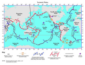
A map of the Earth showing the tectonic plates and the nature of the relative motion at the plate interfaces is shown below (click on the image to enlarge).

ESRT Page5

Source: http://www.regentsearth.com/

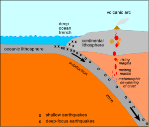
When two tectonic plate converge, one will sink under (subduct) the other. In the case of an oceanic plate converging with a continental plate, the heavier oceanic plate always sinks under the continental plate and may cause mountain building along the edge of the continental plate. When two oceanic plates converge, one will subduct the other, creating a deep mid-ocean trench (i.e., Mariana trench) and possibly forming an arc of islands on the overriding plate (i.e., Aleutian Islands and south Pacific island chains). In the diagram above, you can see that some subduction zones are quite long.

subd_zoneSource: http://www.columbia.edu/~vjd1/subd_zone_basic.htm

The above diagram shows the subducting material from an oceanic plate descending deep into the Earth beneath the overriding continental plate.  New research indicates that the subducting plates maintain their structure to a considerable depth below the surface of the Earth.

On 22 November 2016, an article by Paul Voosen, “’Atlas of the Underworld’ reveals oceans and mountains lost to Earth’s history,” was posted on the sciencemag.org website. The author reports:

“A team of Dutch scientists will announce a catalog of 100 subducted plates, with information about their age, size, and related surface rock records, based on their own tomographic model and cross-checks with other published studies.”

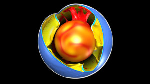
“…geoscientists have begun ….peering into the mantel itself, using earthquake waves that pass through Earth’s interior to generate images resembling computerized tomography (CT) scans. In the past few years, improvements in these tomographic techniques have revealed many of these cold, thick slabs as they free fall in slow motion to their ultimate graveyard—heaps of rock sitting just above Earth’s molten core, 2900 kilometers below.”

The following concept drawing illustrates how a CT scan of the whole Earth might look, with curtains of subducting material surrounding the molten core.

Atlas_1121_1280x720Source: Science / Fabio Crameri

The author notes that research teams around the world are using more than 20 different models to interpret similar tomographic data. As you might expect, results differ. However, a few points are consistent:

  • The subducting slabs in the upper mantle appear to be stiff, straight curtains of lithospheric rock
  • These slabs may flex but they don’t crumble.
  • These two features make it possible to “unwind” the geologic history of individual tectonic slabs and develop a better understanding of the route each slab took to its present location.
  • The geologic history in subducting slabs only stretches back about 250 million years, which is the time it takes for subducting material to fall from the surface to the bottom of the mantle and be fully recycled.

You can read the fill article by Paul Voosen at the following link:

http://www.sciencemag.org/news/2016/11/atlas-underworld-reveals-oceans-and-mountains-lost-earths-history

Hopefully, the “Atlas of the Underworld” will help focus the dialogue among international research teams toward collaborative efforts to improve and standardize the processes and models for building an integrated CT model of our Earth.

A “jet stream” in the Earth’s core

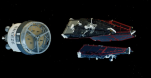
The European Space Agency (ESA) developed the Swarm satellites to make highly accurate and frequent measurements of Earth’s continuously changing magnetic field, with the goal of developing new insights into our planet’s formation, dynamics and environment. The three-satellite Swarm mission was launched on 22 November 2013.

3 satellite SWARMSwarm satellites separating from Russian booster. Source: ESA

ESA’s website for the Swarm mission is at the following link:

http://www.esa.int/Our_Activities/Observing_the_Earth/Swarm/From_core_to_crust

Here ESA explains the value of the measurements made by the Swarm satellites.

“One of the very few ways of probing Earth’s liquid core is to measure the magnetic field it creates and how it changes over time. Since variations in the field directly reflect the flow of fluid in the outermost core, new information from Swarm will further our understanding of the physics and dynamics of Earth’s stormy heart.

The continuous changes in the core field that result in motion of the magnetic poles and reversals are important for the study of Earth’s lithosphere, also known as the ‘crustal’ field, which has induced and remnant magnetized parts. The latter depend on the magnetic properties of the sub-surface rock and the history of Earth’s core field.

We can therefore learn more about the history of the magnetic field and geological activity by studying magnetism in Earth’s crust. As new oceanic crust is created through volcanic activity, iron-rich minerals in the upwelling magma are oriented to magnetic north at the time.

These magnetic stripes are evidence of pole reversals so analyzing the magnetic imprints of the ocean floor allows past core field changes to be reconstructed and also helps to investigate tectonic plate motion.”

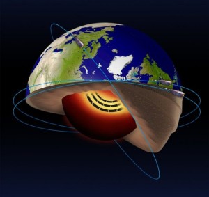
Data from the Swarm satellites indicates that the liquid iron part of the Earth’s core has an internal, 420 km (261 miles) wide “jet stream” circling the core at high latitude at a current speed of about 40 km/year (25 miles/year) and accelerating. In geologic terms, this “jet stream” is significantly faster than typical large scale flows in the core. The basic geometry of this “jet stream” is shown in the following diagram.

jet-stream-earth-core-ESA-e1482190909115Source: ESA

These results were published on 19 December 2016 in the article, An accelerating high-latitude jet in Earth’s core,” on the Nature Geoscience website at the following link:

http://www.nature.com/ngeo/journal/vaop/ncurrent/full/ngeo2859.html

A subscription is required for access to the full paper.

The Swarm mission is ongoing. Watch the ESA’s mission website for more news.

Airbus Delivers its 10,000th Aircraft

Peter Lobner

Airbus was founded on 18 December 1970 and delivered its first aircraft, an A300B2, to Air France on 10 May 1974. This was the world’s first twin-engine, wide body (two aisles) commercial airliner, beating Boeing’s 767, which was not introduced into commercial service until September 1982. The A300 was followed in the early 1980s by a shorter derivative, the A310, and then, later that decade, by the single-aisle A320. The A320 competed directly with the single-aisle Boeing 737 and developed into a very successful family of single-aisle commercial airliners: A318, A319, A320 and A321.

On 14 October 2016, Airbus announced the delivery of its 10,000th aircraft, which was an A350-900 destined for service with Singapore Airlines.

EVE-1236Source: Airbus

In their announcement, Airbus noted:

“The 10,000th Airbus delivery comes as the manufacturer achieves its highest level of production ever and is on track to deliver at least 650 aircraft this year from its extensive product line. These range from 100 to over 600 seats and efficiently meet every airline requirement, from high frequency short haul operations to the world’s longest intercontinental flights.”

You can read the complete Airbus press release at the following link:

http://www.airbus.com/presscentre/pressreleases/press-release-detail/detail/-9b32c4364a/

As noted previously, Airbus beat Boeing to the market for twinjet, wide-body commercial airliners, which are the dominant airliner type on international and high-density routes today. Airbus also was an early adopter of fly-by-wire flight controls and a “glass cockpit”, which they first introduced in the A320 family.

In October 2007, the ultra-large A380 entered service, taking the honors from the venerable Boeing 747 as the largest commercial airliner.   Rather than compete head-to-head with the A380, Boeing opted for stretching its 777 and developing a smaller, more advanced and more efficient, all-composite new airliner, the 787, which was introduced in airline service 2011.

Airbus countered with the A350 XWB in 2013. This is the first Airbus with fuselage and wing structures made primarily of carbon fiber composite material, similar to the Boeing 787.

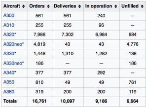
The current Airbus product line comprises a total of 16 models in four aircraft families: A320 (single aisle), A330 (two aisle wide body), A350 XWB (two aisle wide body) and A380 (twin deck, two aisle wide body). The following table summarizes Airbus commercial jet orders, deliveries and operational status as of 30 November 2016.

Airbus orders* Includes all models in this family. Source: https://en.wikipedia.org/wiki/Airbus

Boeing is the primary competitor to Airbus. Boeing’s first commercial jet airliner, the 707, began commercial service Pan American World Airways on 26 October 1958. The current Boeing product line comprises five airplane families: 737 (single-aisle), 747 (twin deck, two aisle wide body), 767 (wide body, freighter only), 777 (two aisle wide body) and 787 (two aisle wide body).

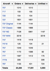
The following table summarizes Boeing’s commercial jet orders, deliveries and operational status as of 30 June 2016. In that table, note that the Boeing 717 started life in 1965 as the Douglas DC-9, which in 1980 became the McDonnell-Douglas MD-80 (series) / MD-90 (series) before Boeing acquired McDonnell-Douglas in 1997. Then the latest version, the MD-95, became the Boeing 717.

Boeing commercial order status 30Jun2016

Source: https://en.wikipedia.org/wiki/Boeing_Commercial_Airplanes

Boeing’s official sales projections for 2016 are for 740 – 745 aircraft. Industry reports suggest a lower sales total is more likely because of weak worldwide sales of wide body aircraft.

Not including the earliest Boeing models (707, 720, 727) or the Douglas DC-9 derived 717, here’s how the modern competition stacks up between Airbus and Boeing.

Single-aisle twinjet:

  • 12,805 Airbus A320 family (A318, A319, A320 and A321)
  • 14,527 Boeing 737 and 757

Two-aisle twinjet:

  • 3,260 Airbus A300, A310, A330 and A350
  • 3,912 Boeing 767, 777 and 787

Twin aisle four jet heavy:

  • 696 Airbus A340 and A380
  • 1,543 Boeing 747

These simple metrics show how close the competition is between Airbus and Boeing. It will be interesting to see how these large airframe manufacturers fare in the next decade as they face more international competition, primarily at the lower end of their product range: the single-aisle twinjets. Former regional jet manufacturers Bombardier (Canada) and Embraer (Brazil) are now offering larger aircraft that can compete effectively in some markets. For example, the new Bombardier C Series is optimized for the 100 – 150 market segment. The Embraer E170/175/190/195 families offer capacities from 70 to 124 seats, and range up to 3,943 km (2,450 miles).  Other new manufacturers soon will be entering this market segment, including Russia’s Sukhoi Superjet 100 with about 108 seats, the Chinese Comac C919 with up to 168 seats, and Japan’s Mitsubishi Regional Jet with 70 – 80 seats.

At the upper end of the market, demand for four jet heavy aircraft is dwindling. Boeing is reducing the production rate of its 747-8, and some airlines are planning to not renew their leases on A380s currently in operation.

It will be interesting to watch how Airbus and Boeing respond to this increasing competition and to increasing pressure for controlling aircraft engine emissions after the Paris Agreement became effective in November 2016.

Qualcomm Tricorder XPrize Competition Down to Two Finalists

Peter Lobner

I described the Qualcomm Tricorder XPrize competition in my 10 March 2015 post, “Medical Tricorder Technology is Closer Than you Think.” The goal of the competition is to develop a real-world equivalent of the Star Trek Tricorder, with the following basic capabilities and features:

  • Diagnose at least 13 different health conditions including the following nine required conditions: anemia, atrial fibrillation, chronic obstructive pulmonary disease, diabetes, leukocytosis, pneumonia, ottis media, sleep apnea and urinary tract infection.
  • Weigh less than five pounds

At the time of my last update in December 2015, the following seven teams had been selected to compete in the extended Final Round for $10 million in prize money.

  • Aezon (U.S.)
  • Clouddx (Canada)
  • Danvantri (India)
  • DMI (U.S.)
  • Dynamical Biomarkers Group (Taiwan)
  • Final Frontier Medical Devices (U.S.)
  • Intellesens-Scanadu (UK)

Each of these teams submitted their final working prototypes for evaluation in Q3 2016. On 13 December 2016, Qualcomm Tricorder XPrize announced that they had selected two teams to continue into the finals:

“Congratulations to our two final teams, Dynamical Biomarkers Group and Final Frontier Medical Devices, who will proceed to the final phase in the $10M Qualcomm Tricorder XPRIZE. Both teams’ devices will undergo consumer testing over the next few months at the Altman Clinical Translational Research Institute at the University of California San Diego, and the winner will be announced in Q2, 2017.”

Both teams are required to deliver 45 kits for testing.

The XPrize will be split with $6 million going to the winning team, $2 million going to the runner-up, and $1 million for the team that receives the highest vital signs score in the final round. An additional $1M already has been awarded in milestone prizes.

The two competing devices are briefly described below. For more information, visit the Qualcomm Tricorder XPrize website at the following link:

http://tricorder.xprize.org

Dynamical Biomarkers Group

DBG_TricorderSource: Qualcomm Tricorder XPrize

 Key system features:

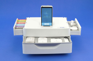
  • Comprised of three modules: Smart Vital-Sense Monitor; Smart Blood-Urine Test Kit; Smart Scope Module.
  • Includes technologies for physiologic signal analysis, image processing, and biomarker detection.
  • Smartphone app executes simple, interactive screening process that guides the users to carry out specific tests to generate disease diagnosis. The phone’s on-board camera is used to capture images of test strips. The smartphone communicates to the base unit via Bluetooth.
  • The base unit uploads collected data to a remote server for analysis.

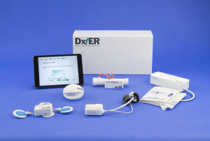
Final Frontier Medical Devices: DxtER

DexTR_TricorderSource: Qualcomm Tricorder XPrize

Key system features:

  • DxtER is designed as a consumer product for monitoring your health and diagnosing illnesses in the comfort of your own home.
  • Non-invasive sensors collect data about your vital signs, body chemistry, and biological functions.
  • An iPad Mini with an on-board AI diagnostic app synthesizes the health data to generate a diagnosis.
  • While DxtER functions autonomously, it also can share data with a remote healthcare provider.

Best wishes to both teams as they enter the final round of this challenging competition, which could significantly change the way some basic medical services are delivered in the U.S. and around the world.

First Ever Antimatter Spectroscopy in ALPHA-2

Peter Lobner

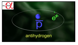
ALPHA-2 is a device at the European particle physics laboratory at CERN, in Meyrin, Switzerland used for collecting and analyzing antimatter, or more specifically, antihydrogen.  A common hydrogen atom is composed of an electron and proton.  In contrast, an  antihydrogen atom is made up of a positron bound to an antiproton.

Screen Shot 2016-12-22 at 4.19.01 PMSource: CERN

The ALPHA-2 project homepage is at the following link:
http://alpha.web.cern.ch

On 16 December 2016, the ALPHA-2 team reported the first ever optical spectroscopic observation of the 1S-2S (ground state – 1st excited state) transition of antihydrogen that had been trapped and excited by a laser.

“This is the first time a spectral line has been observed in antimatter. ……..This first result implies that the 1S-2S transition in hydrogen and antihydrogen are not too different, and the next steps are to measure the transition’s lineshape and increase the precision of the measurement.”

In the ALPHA-2 online news article, “Observation of the 1S-2S Transition in Trapped Antihydrogen Published in Nature,” you will find two short videos explaining how this experiment was conducted:

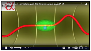
  • Antihydrogen formation and 1S-2S excitation in ALPHA
  • ALPHA first ever optical spectroscopy of a pure anti atom

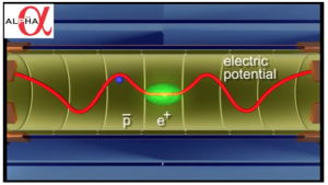
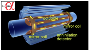
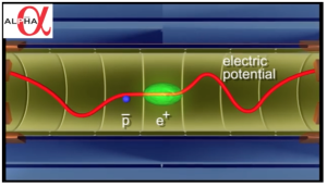
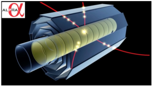
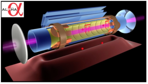
These videos describe the process for creating antihydrogen within a magnetic trap (octupole & mirror coils) containing positrons and antiprotons. Selected screenshots from the first video are reproduced below to illustrate the process of creating and exciting antihydrogen and measuring the results.

Alpha2 mirror trap

The potentials along the trap are manipulated to allow the initially separated positron and antiproton populations to combine, interact and form antihydrogen.

Combining positron & antiproton 1Combining positron & antiproton 2Combining positron & antiproton 3

If the magnetic trap is turned off, the antihydrogen atoms will drift into the inner wall of the device and immediately be annihilated, releasing pions that are detected by the “annihilation detectors” surrounding the magnetic trap. This 3-layer detector provides a means for counting antihydrogen atoms.

Detecting antihydrogen

A tuned laser is used to excite the antihydrogen atoms in the magnetic trap from the 1S (ground) state to the 2S (first excited) state. The interaction of the laser with the antihydrogen atoms is determined by counting the number of free antiprotons annihilating after photo ionization (an excited antihydrogen atom loses its positron) and counting all remaining antihydrogen atoms. Two cases were investigated: (1) laser tuned for resonance of the 1S-2S transition, and (2) laser detuned, not at resonance frequency. The observed differences between these two cases confirmed that, “the on-resonance laser light is interacting with the antihydrogen atoms via their 1S-2S transition.”

Exciting antihydrogen

The ALPHA-2 team reported that the accuracy of the current antihydrogen measurement of the 1S-2S transition is about “a few parts in 10 billion” (1010). In comparison, this transition in common hydrogen has been measured to an accuracy of “a few parts in a thousand trillion” (1015).

For more information, see the 19 December 2016 article by Adrian Cho, “Deep probe of antimatter puts Einstein’s special relativity to the test,” which is posted on the Sciencemag.org website at the following link:

http://www.sciencemag.org/news/2016/12/deep-probe-antimatter-puts-einstein-s-special-relativity-test?utm_campaign=news_daily_2016-12-19&et_rid=215579562&et_cid=1062570

Polyhedral Projections Improve the Accurately of Mapping the Earth on a 2D Surface

Peter Lobner

Representing the Earth’s 3-dimensional surface on a 2-dimensional map is a problem that has vexed cartographers through the ages. The difficulties in creating a 2D map of the world include maintaining continental shapes, distances, areas, and relative positions so the 2D map is useful for its intended purpose.

Old world mapWorld map circa 1630. Source: World Maps Online

In this article, we’ll look at selected classical projection schemes for creating a 2D world map followed by polyhedral projection schemes, the newest of which, the AuthaGraph World Map, may yield the most accurate maps of the world.

1. Classical Projections

To get an appreciation for the large number of classical projection schemes that have been developed to create 2D world maps, I suggest that you start with a visit to the Radical Cartography website at the following link, where you’ll find descriptions of 31 classical projections (and 2 polyhedral projections).

http://www.radicalcartography.net/?projectionref

Now let’s take a look at the following classical projection schemes.

  • 1569 Mercator projection
  • 1855 Gail equal-area projection & 1967 Gail-Peters equal-area projection
  • 1805 Mollweide equal-area projection
  • 1923 Goode homolosine projection

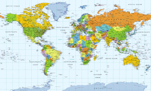
Mercator projection

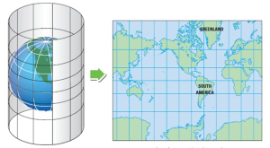
The Mercator world map is a cylindrical projection that is created as shown in the following diagram.

Cylindrical projection

Source: adapted from http://images.slideplayer.com/15/4659006/slides/slide_17.jpg

Mercator map

Source:https://tripinbrooklyn.files.wordpress.com/2008/04/new_world60_small.gif?w=450

Important characteristics of a Mercator map are:

  • It represents a line of constant course (rhumb line) as a straight line segments with a constant angle to the meridians on the map. Therefore, Mercator maps became the standard map projection for nautical purposes.
  • The linear scale of a Mercator map increases with latitude. This means that geographical objects further from the equator appear disproportionately larger than objects near the equator. You can see this in the relative size comparison of Greenland and Africa, below.

Greenland & AfricaThe size distortion on Mercator maps has led to significant criticism of this projection, primarily because it conveys a distorted perception of the overall geometry of the planet.

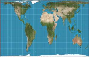
Gail equal-area projection & Gail-Peters equal-area projection

James Gail developed a cylindrical “equal area” projection that attempted to rectify the significant area distortions in Mercator projections. There are several similar cylindrical “equal-area” projection schemes that differ mainly in the scaling factor (standard parallel) used.

In 1967, German filmmaker Arno Peters “re-invented” the century old Gail equal-area projection and claimed that it better represented the interests of the many small nations in the equatorial region that were marginalized (at least in terms of area) in the Mercator projection.   Arno’s focus was on the social stigma of this marginalization. UNESCO favors the Gail-Peters projection.

Gall–Peters_projection_SWSource: By Strebe – Own work, CC BY-SA 3.0, https://commons.wikimedia.org/w/index.php?curid=16115242

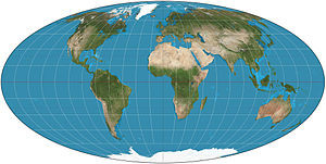
Mollweide equal-area projection

The key strength of this projection is in the accuracy of land areas, but with compromises in angle and shape. The central meridian is perpendicular to the equator and one-half the length of the equator.  The whole earth is depicted in a proportional 2:1 ellipse

This projection is popular in maps depicting global distributions. Astronomers also use the Mollweide equal-area projection for maps of the night sky.

Mollweide_projection_SW

Source: Wikimedia Commons

An interrupted Mollweide map addresses the issue of shape distortion, while preserving the relative accuracy of land areas.

Interrupted Mollweide

Source: http://www.progonos.com/furuti/MapProj/Normal/ProjInt/ProjIntC/projIntC.html

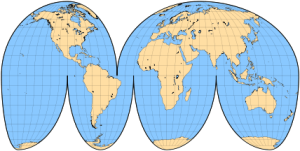
Goode homolosine projection

This projection is a combination of sinusoidal (to mid latitudes) and Mollweide at higher latitudes. It has no distortion along the equator or the vertical meridians in the middle latitudes. It was developed as a teaching replacement for Mercator maps. It is used by the U.S. Geologic Service (USGS) and also is found in many school atlases. The version shown below includes extensions repeating a few portions in order to show Greenland and eastern Russia uninterrupted.

Goode Homolosine Projection

Source: http://www.progonos.com/furuti/MapProj/Normal/ProjInt/ProjIntC/projIntC.html

2. Polyhedral Projections

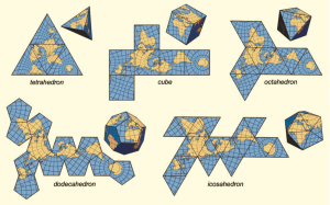
In his 1525 book, Underweysung der Messung (Painter’s Manual), German printmaker Abrecht Durer presented the earliest known examples of how a sphere could be represented by a polyhedron that could be unfolded to lie flat for printing. The polyhedral shapes he described included the icosahedron and the cuboctahedron.

While Durer did not apply these ideas at the time to cartography, his work laid the foundation for the use of complex polyhedral shapes to create 2D maps of the globe. Several examples are shown in the following diagram.

Polygom globes & mapsSource: J.J. van Wijk, “Unfolding the Earth: Myriahedral Projections”

Now we’ll take a look at the following polyhedral maps:

  • 1909 Bernard J. S. Cahill’s butterfly map
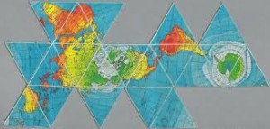
  • 1943 & 1954 R. Buckminster Fuller’s Dymaxion globe & map
  • 1975 Cahill-Keyes World Map
  • 1996 Waterman polyhedron projections
  • 2008 Jarke J. van Wijk myriahedral projection
  • 2016 AuthaGraph World Map

Bernard J. S. Cahill’s Butterfly Map

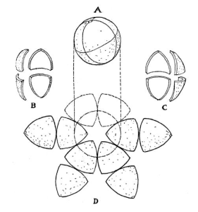
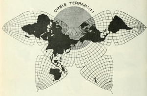
Cahill was the inventor of the “butterfly map,” which is comprised of eight symmetrical triangular lobes. The basic geometry of Cahill’s process for unfolding a globe into eight symmetrical octants and producing a butterfly map is shown in the following diagram made by Cahill in his original 1909 article on this mapping process.

Cahill mapping process

The octants were arrayed four above and four below the equator. As shown below, the octant starting point in longitude (meridian) was strategically selected so all continents would be uninterrupted on the 2D map surface. This type of projection offered a 2D world map with much better fidelity to the globe than a Mercator projection.

Cahill butterfly mapCahill’s 1909 map. Source: genekeys.com

You can read Cahill’s original 1909 article in the Scottish Geographical Magazine at the following link:

http://www.genekeyes.com/CAHILL-1909/Cahill-1909.html

R. Buckminster Fuller’s Dymaxion Globe & Map

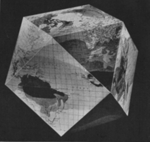
In the 1940s, R. Buckminster Fuller developed his approach for mapping the spherical globe onto a polyhedron. He first used a 14-sided cuboctahedron (8 triangular faces and 6 square faces), with each edge of the polyhedron representing a partial great circle on the globe. For each polyhedral face, Fuller developed his own projection of the corresponding surface of the globe. Fuller first published this map in Life magazine on 1 March 1943 along with cut-outs and instructions for assembling a polygonal globe.

Dymaxion map 1943Fuller’s 1943 Dymaxion map. Source: Life magazine

RBF 1st Dymaxion globeFuller’s 1943 cuboctahedron Dymaxion globe.  Source: Life magazine

You can see the complete Life magazine article, “R. Buckminster Fuller’s Dymaxion World,” at the following link:

https://books.google.co.uk/books?id=WlEEAAAAMBAJ&pg=PA41&source=gbs_toc_r&redir_esc=y&hl=en#v=onepage&q&f=false

A later, improved version, known as the Airocean World Map, was published in 1954. This version of Fuller’s Dymaxion map, shown below, was based on a regular icosahedron, which has 20 triangular faces with each edge representing a partial great circle on a globe.

Dymaxion mapSource: http://www.genekeyes.com/FULLER/1972-BF-BNS-.25-.95.1-Sc-1.jpg

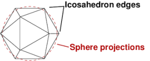
You can see in the diagram below that there are relatively modest variations between the icosahedron’s 20 surfaces and the surface of a sphere.

Sphere vs icosahedron

Source: https://sciencevspseudoscience.files.wordpress.com/2013/09/embedded_icosahedron.png

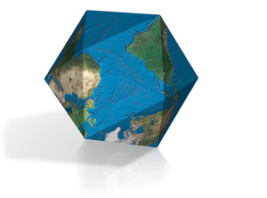
Dymaxion globe2

Fuller’s icosahedron Dymaxion globe.   Source: http://workingknowledge.com/blog/wp-content/uploads/2012/03/DymaxionPic.jpg

You can watch an animation of a spherical globe transforming into an icosahedron and then unfolding into a 2D map at the following link:

https://upload.wikimedia.org/wikipedia/commons/b/bb/Dymaxion_2003_animation_small1.gif

Cahill-Keyes World Map

The Cahill–Keyes World Map developed in 1975 is an adaptation of the 1909 Cahill butterfly map. The Cahill-Keyes World map also is a polyhedral map comprised of eight symmetrical octants with a compromise treatment for Antarctica. Desirable characteristics include symmetry of component maps (octants) and scalability, which allows the map to continue to work well even at high resolution.

Cahill-KeyesSource: http://imgur.com/GICCYmz

Waterman polyhedron projection maps

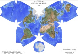
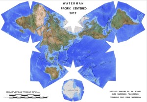
The Waterman polyhedron projection is another variation of the “butterfly” projection that is created by unfolding the globe into eight symmetric, truncated octahedrons plus a separate eight-sided piece for Antarctica.  The Atlantic-centered projection and the comparable Pacific-centered projection are shown below.

Waterman Atlantic

Waterman Pacific

Source, two maps: watermanpolyhedron.com

The Waterman home page is at the following link:
http://watermanpolyhedron.com/deploy/

Here the developers make the following claims:

“Shows the equator clearly, as well as continental shapes, distances (within 10 %), areas (within 10 %) angular distortions (within 20 degrees), and relative positions, as a compromise: statistically better than all other World maps.”

Myriahedral projection maps

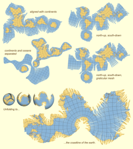
A myriahedron is a polyhedron with a myriad of faces. This projection was developed in 2008 by Jarke J. van Wijk and is described in detail in the article, “Unfolding the Earth: Myriahedral Projections,” in the Cartographic Journal, which you can read at the following link:

https://www.win.tue.nl/~vanwijk/myriahedral/

Examples of myriahedral projections are shown below. As you can see, there are many different ways to define a 2D map using a myriahedral projection.

Myriahedral projectionSource: https://www.win.tue.nl/~vanwijk/myriahedral/geo_aligned_maps.png

AuthaGraph World Map

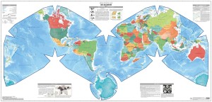
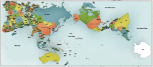
The latest attempt to accurately map the globe on a 2D surface is the AuthaGraph World Map, made by equally dividing a spherical surface into 96 triangles, transferring it to a tetrahedron while maintaining areas proportions and unfolding it to be a rectangle. The developers explain the basic process as follows:

“…we developed an original world map called ‘AuthaGraph World Map’ which represents all oceans, continents including Antarctica which has been neglected in many existing maps in substantially proper sizes. These fit in a rectangular frame without interruptions and overlaps. The idea of this projection method was developed through an intensive research by modeling spheres and polyhedra. And then we applied the idea to cartography as one of the most useful applications.”

 AuthaGraph World Map 2The AuthaGraph World Map. Source: AuthaGraph

For detailed information on this mapping process, I suggest that you start at the AuthaGraph home page:

http://www.authagraph.com/top/?lang=en

From here, select “Details” for a comprehensive review of the mapping technology behind the AuthaGraph World Map.

Also check out the 4 November 2016 article on the AuthaGraph World Map, “This Might Be the Most Accurate Map of the World,” at the following link:

http://motherboard.vice.com/read/this-might-be-the-most-accurate-world-map-we-have?utm_source=howtogeek&utm_medium=email&utm_campaign=newsletter

What to do with Carbon Dioxide

Peter Lobner

In my 17 December 2016 post, “Climate Change and Nuclear Power,” there is a chart that shows the results of a comparative life cycle greenhouse gas (GHG) analysis for 10 electric power-generating technologies. In that chart, it is clear how carbon dioxide capture and storage technologies can greatly reduce the GHG emissions from gas and coal generators.

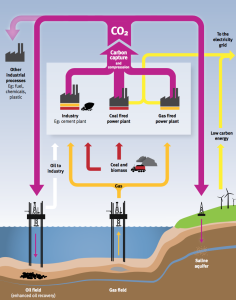
An overview of carbon dioxide capture and storage technology is presented in a December 2010 briefing paper issued by the London Imperial College. This paper includes the following process flow diagram showing the capture of CO2 from major sources, use or storage of CO2 underground, and use of CO2 as a feedstock in other industrial processes. Click on the graphic to enlarge.

Carbon capture and storage process

You can download the London Imperial College briefing paper at the following link:

https://www.imperial.ac.uk/media/imperial-college/grantham-institute/public/publications/briefing-papers/Carbon-dioxide-storage—-Grantham-BP-4.pdf

Here is a brief look at selected technologies being developed for underground storage (sequestration) and industrial utilization of CO2.

Store in basalt formations by making carbonate rock

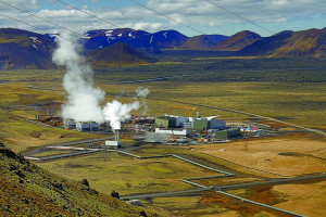
Iceland generates about 85% of its electric power from renewable resources, primarily hydro and geothermal. Nonetheless, Reykjavik Energy initiated a project called CarbFix at their 303 MWe Hellisheidi geothermal power plant to control its rather modest CO2 emissions along with hydrogen sulfide and other gases found in geothermal steam.

Hellisheidi geothermal power plantHellisheidi geothermal power plant. Source: Power Technology

The process system collects the CO2 and other gases, dissolves the gas in large volumes of water, and injects the water into porous, basaltic rock 400 – 800 meters (1,312 – 2,624 feet) below the surface. In the deep rock strata, the CO2 undergoes chemical reactions with the naturally occurring calcium, magnesium and iron in the basalt, permanently immobilizing the CO2 as environmentally benign carbonates. There typically are large quantities of calcium, magnesium and iron in basalt, giving a basalt formation a large CO2 storage capacity.

The surprising aspect of this process is that the injected CO2 was turned into hard rock very rapidly. Researchers found that in two years, more that 95% of the CO2 injected into the basaltic formation had been turned into carbonate.

For more information, see the 9 June 2016 Washington Post article by Chris Mooney, “This Iceland plant just turned carbon dioxide into solid rock — and they did it super fast,” at the following link:

https://www.washingtonpost.com/news/energy-environment/wp/2016/06/09/scientists-in-iceland-have-a-solution-to-our-carbon-dioxide-problem-turn-it-into-stone/?utm_term=.886f1ca92c56

The author notes,

“The researchers are enthusiastic about their possible solution, although they caution that they are still in the process of scaling up to be able to handle anything approaching the enormous amounts of carbon dioxide that are being emitted around the globe — and that transporting carbon dioxide to locations featuring basalt, and injecting it in large volumes along with even bigger amounts of water, would be a complex affair.”

Basalt formations are common worldwide, making up about 10% of continental rock and most of the ocean floor. Iceland is about 90% basalt.

Detailed results of this Reykjavik Energy project are reported in a May 2016 paper by J.M. Matter, M. Stute, et al., Rapid carbon mineralization for permanent disposal of anthropogenic carbon dioxide emissions,” which is available on the Research Gate website at the following link:

https://www.researchgate.net/publication/303450549_Rapid_carbon_mineralization_for_permanent_disposal_of_anthropogenic_carbon_dioxide_emissions

Similar findings were made in a separate pilot project in the U.S. conducted by Pacific Northwest National Laboratory and the Big Sky Carbon Sequestration Partnership. In this project, 1,000 tons of pressurized liquid CO2 were injected into a basalt formation in eastern Washington state in 2013. Samples taken two years later confirmed that the CO2 had been converted to carbonate minerals.

These results were published in a November 2016 paper by B. P McGrail, et al., “Field Validation of Supercritical CO2 Reactivity with Basalts.” The abstract and the paper are available at the following link:

http://pubs.acs.org/doi/pdf/10.1021/acs.estlett.6b00387

Store in fractures in deep crystalline rock

Lawrence Berkeley National Laboratory has established an initiative dubbed SubTER (Subsurface Technology and Engineering Research, Development and Demonstration Crosscut) to study how rocks fracture and to develop a predictive understanding of fracture control. A key facility is an observatory set up 1,478 meters (4,850 feet) below the surface in the former Homestake mine near Lead, South Dakota (note: Berkeley shares this mine with the neutrino and dark matter detectors of the Sanford Underground Research Facility). The results of the Berkeley effort are expected to be applicable both to energy production and waste storage strategies, including carbon capture and sequestration.

You can read more about this Berkeley project in the article, “Underground Science: Berkeley Lab Digs Deep For Clean Energy Solutions,” on the Global Energy World website at the following link:

http://www.newswise.com/articles/view/663141/?sc=rssn&utm_source=feedburner&utm_medium=feed&utm_campaign=Feed%3A+NewswiseScinews+%28Newswise%3A+SciNews%29

Make ethanol

Researchers at the Department of Energy’s Oak Ridge National Laboratory (ORNL) have defined an efficient electrochemical process for converting CO2 into ethanol. While direct electrochemical conversion of CO2 to useful products has been studied for several decades, the yields of most reactions have been very low (single-digit percentages) and some required expensive catalysts.

Key points about the new process developed by ORNL are:

  • The electro-reduction process occurs in CO2 saturated water at ambient temperature and pressure with modest electrical requirements
  • The nanotechnology catalyst is made from inexpensive materials: carbon nanospike (CNS) electrode with electro-nucleated copper nanoparticles (Cu/CNS). The Cu/CNS catalyst is unusual because it primarily produces ethanol.
  • Process yield (conversion efficiency from CO2 to ethanol) is high: about 63%
  • The process can be scaled up.
  • A process like this could be used in an energy storage / conversion system that consumes extra electricity when it’s available and produces / stores ethanol for later use.

You can read more on this process in the 19 October 2016 article, “Scientists just accidentally discovered a process that turns CO2 directly into ethanol,” on the Science Alert website at the following link

http://www.sciencealert.com/scientists-just-accidentally-discovered-a-process-that-turns-co2-directly-into-ethanol

The full paper is available on the Chemistry Select website at the following link:

http://onlinelibrary.wiley.com/doi/10.1002/slct.201601169/full

Emergent Gravity Theory Passes its First Test

Peter Lobner

In 2010, Prof. Erik Verlinde, University of Amsterdam, Delta Institute for Theoretical Physics, published the paper, “The Origin of Gravity and the Laws of Newton.” In this paper, the author concluded:

 “The results of this paper suggest gravity arises as an entropic force, once space and time themselves have emerged. If the gravity and space time can indeed be explained as emergent phenomena, this should have important implications for many areas in which gravity plays a central role. It would be especially interesting to investigate the consequences for cosmology. For instance, the way redshifts arise from entropy gradients could lead to many new insights.

The derivation of the Einstein equations presented in this paper is analogous to previous works, in particular [the 1995 paper by T. Jacobson, ‘Thermodynamics of space-time: The Einstein equation of state.’]. Also other authors have proposed that gravity has an entropic or thermodynamic origin, see for instance [the paper by T. Padmanabhan, ‘Thermodynamical Aspects of Gravity: New insights.’]. But we have added an important element that is new. Instead of only focusing on the equations that govern the gravitational field, we uncovered what is the origin of force and inertia in a context in which space is emerging. We identified a cause, a mechanism, for gravity. It is driven by differences in entropy, in whatever way defined, and a consequence of the statistical averaged random dynamics at the microscopic level. The reason why gravity has to keep track of energies as well as entropy differences is now clear. It has to, because this is what causes motion!”

You can download Prof. Verlinde’s 2010 paper at the following link:

https://arxiv.org/pdf/1001.0785.pdf

On 8 November 2016, Delta Institute announced that Prof. Verlinde had published a new research paper, “Emergent Gravity and the Dark Universe,” expanding on his previous work. You can read this announcement and see a short video by Prof. Verlinde on the Delta Institute website at the following link:

http://www.d-itp.nl/news/list/list/content/folder/press-releases/2016/11/new-theory-of-gravity-might-explain-dark-matter.html

You can download this new paper at the following link:

https://arxiv.org/abs/1611.02269

I found it helpful to start with Section 8, Discussion and Outlook, which is the closest you will find to a layman’s description of the theory.

On the Physics.org website, a short 8 November 2016 article, “New Theory of Gravity Might Explain Dark Matter,” provides a good synopsis of Verlinde’s emergent gravity theory:

“According to Verlinde, gravity is not a fundamental force of nature, but an emergent phenomenon. In the same way that temperature arises from the movement of microscopic particles, gravity emerges from the changes of fundamental bits of information, stored in the very structure of spacetime……

According to Erik Verlinde, there is no need to add a mysterious dark matter particle to the theory……Verlinde shows how his theory of gravity accurately predicts the velocities by which the stars rotate around the center of the Milky Way, as well as the motion of stars inside other galaxies.

One of the ingredients in Verlinde’s theory is an adaptation of the holographic principle, introduced by his tutor Gerard ‘t Hooft (Nobel Prize 1999, Utrecht University) and Leonard Susskind (Stanford University). According to the holographic principle, all the information in the entire universe can be described on a giant imaginary sphere around it. Verlinde now shows that this idea is not quite correct—part of the information in our universe is contained in space itself.

This extra information is required to describe that other dark component of the universe: Dark energy, which is believed to be responsible for the accelerated expansion of the universe. Investigating the effects of this additional information on ordinary matter, Verlinde comes to a stunning conclusion. Whereas ordinary gravity can be encoded using the information on the imaginary sphere around the universe, as he showed in his 2010 work, the result of the additional information in the bulk of space is a force that nicely matches that attributed to dark matter.”

Read the full Physics.org article at the following link:

http://phys.org/news/2016-11-theory-gravity-dark.html#jCp

On 12 December 2016, a team from Leiden Observatory in The Netherlands reported favorable results of the first test of the emergent gravity theory. Their paper, “First Test of Verlinde’s Theory of Emergent Gravity Using Weak Gravitational Lensing Measurements,” was published in the Monthly Notices of the Royal Astronomical Society. The complete paper is available at the following link:

http://mnras.oxfordjournals.org/content/early/2016/12/09/mnras.stw3192

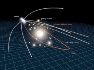
An example of a gravitational lens is shown in the following diagram.

Gravitational-lensing-galaxyApril12_2010-1024x768-e1481555047928 Source: NASA, ESA & L. Calça

As seen from the Earth, the light from the galaxy at the left is bent by the gravitational forces of the galactic cluster in the center, much like light passing though an optical lens.

The Leiden Observatory authors reported:

“We find that the prediction from EG, despite requiring no free parameters, is in good agreement with the observed galaxy-galaxy lensing profiles in four different stellar mass bins. Although this performance is remarkable, this study is only a first step. Further advancements on both the theoretical framework and observational tests of EG are needed before it can be considered a fully developed and solidly tested theory.”

These are exciting times! As noted in the Physics.org article, “We might be standing on the brink of a new scientific revolution that will radically change our views on the very nature of space, time and gravity.”

The Navy’s Troubled Littoral Combat Ship (LCS) Program is Delivering a Costly, Unreliable, Marginal Weapons System

Peter Lobner

Updated 9 January 2020

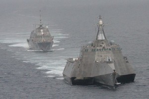
The LCS program consists of two different, but operationally comparable ship designs:

  • LCS-1 Freedom-class monohull built by Marinette Marine
  • LCS-2 Independence-class trimaran built by Austal USA.

These relatively small surface combatants have full load displacements in the 3,400 – 3,900 ton range, making them smaller than most destroyer and frigate-class ships in the world’s navies.

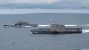
lcs-1-and-lcs-2-web120502-n-zz999-009LCS-2 in foreground & LCS-1 in background. Source: U.S. NavyLCS-2-Indepenence-LCS-1-Freedom-7136872711_c3ddf9d43bLCS-1 on left & LCS-2 on right. Source: U.S. Navy

Originally LCS was conceived as a fleet of 52 small, fast, multi-mission ships designed to fight in littoral (shallow, coastal) waters, with roll-on / roll-off mission packages intended to give these ships unprecedented operational flexibility. In concept, it was expected that mission module changes could be conducted in any port in a matter of hours. In a 2010 Department of Defense (DoD) Selected Acquisition Report, the primary missions for the LCS were described as:

“…littoral surface warfare operations emphasizing prosecution of small boats, mine warfare, and littoral anti-submarine warfare. Its high speed and ability to operate at economical loiter speeds will enable fast and calculated response to small boat threats, mine laying and quiet diesel submarines. LCS employment of networked sensors for Intelligence, Surveillance, and Reconnaissance (ISR) in support of Special Operations Forces (SOF) will directly enhance littoral mobility. Its shallow draft will allow easier excursions into shallower areas for both mine countermeasures and small boat prosecution. Using LCS against these asymmetrical threats will enable Joint Commanders to concentrate multi-mission combatants on primary missions such as precision strike, battle group escort and theater air defense.”

Both competing firms met a Congressionally-mandated cost target of $460 million per unit, and, in December 2010, Congress gave the Navy authority to split the procurement rather than declare a single winner. Another unique aspect of the LCS program was that the Defense Acquisition Board split the procurement further into the following two separate and distinct programs with separate reporting requirements:

  • The two “Seaframe” programs (for the two basic ship designs, LCS-1 and LCS-2)
  • The Mission Module programs (for the different mission modules needed to enable an LCS seaframe to perform specific missions)

When the end product is intended to be an integrated combatant vessel, you don’t need to be a systems analyst to know that trouble is brewing in the interfaces between the seaframes and the mission modules somewhere along the critical path to LCS deployment.

There are three LCS mission modules:

  • Surface warfare (SUW)
  • Anti-submarine (ASW)
  • Mine countermeasures (MCM)

These mission modules are described briefly below:

Surface warfare (SUW)

Each LCS is lightly armed since its design basis surface threat is an individual small, armed boat or a swarm of such boats. The basic anti-surface armament on an LCS seaframe includes a single 57 mm main gun in a bow turret and everal small (.50 cal) machine guns.  The SUW module adds twin 30mm Bushmaster cannons, an aviation unit, a maritime security module (small boats), and relatively short-range surface-to-surface missiles.

Each LCS has a hanger bay for its embarked aviation unit, which is comprised of one manned MH-60R Sea Hawk helicopter and one MQ-8B Fire Scout unmanned aerial vehicle (UAV, a small helicopter). As part of the SUW module, these aviation assets are intended to be used to identify, track, and help prosecute surface targets.

That original short-range missile collaboration with the Army failed when the Army withdrew from the program. As of December 2016, the Navy is continuing to conduct operational tests of a different Army short-range missile, the Longbow Hellfire, to fill the gap in the SUW module and improve the LCS’s capability to defend against fast inshore attack craft.

In addition to the elements of the SUW module described above, each LCS has a RIM-116 Rolling Airframe Missile (RAM) system or a SeaRAM system intended primarily for anti-air point defense (range 5 – 6 miles) against cruise missiles. A modified version of the RAM has limited capabilities for use against helicopters and nearby small surface targets.

In 2015, the Navy redefined the first increment of the LCS SUW capability as comprising the Navy’s Visit, Board, Search and Seizure (VBSS) teams. This limited “surface warfare” function is comparable to the mission of a Coast Guard cutter.

While the LCS was not originally designed to have a long-range (over the horizon) strike capability, the Navy is seeking to remedy this oversight and is operationally testing two existing missile systems to determine their suitability for installation on the LCS fleet. These missiles are the Boeing Harpoon and the Norwegian Konigsberg Naval Strike Missile (NSM). Both can be employed against sea and land targets.

Anti-submarine (ASW)

The LCS does not yet have an operational anti-submarine warfare (ASW) capability because of ongoing delays in developing this mission module.

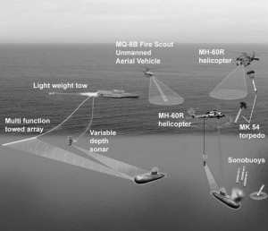
The sonar suite is comprised of a continuously active variable depth sonar, a multi-function towed array sonar, and a torpedo defense sonar. For the ASW mission, the MH-60R Sea Hawk helicopter will be equipped with sonobuoys, dipping sonar and torpedoes for prosecuting submarines. The MQ-8B Fire Scout UAV also can support the ASW mission.

Use of these ASW mission elements is shown in the following diagram (click on the graphic to enlarge):

asw_lcsSource: U.S. Navy

In 2015, the Navy asked for significant weight reduction in the 105 ton ASW module.

Originally, initial operational capability (IOC) was expected to be 2016. It appears that the ASW mission package is on track for an IOC in late 2018, after completing development testing and initial operational test & evaluation.

Mine Countermeasures (MCM)

The LCS does not yet have an operational mine countermeasures capability. The original complex deployment plan included three different unmanned vehicles that were to be deployed in increments.

  • Lockheed Martin Remote Multi-mission Vehicle (RMMV) would tow a sonar system for conducting “volume searches” for mines
  • Textron Common Unmanned Surface Vehicle (CUSV) would tow minesweeping hardware.
  • General Dynamics Knifefish unmanned underwater vehicle would hunt for buried mines

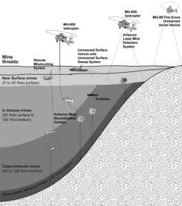
For the MCM mission, the MH-60R Sea Hawk helicopter will be equipped with an airborne laser mine detection system and will be capable of operating an airborne mine neutralization system. The MQ-8B Fire Scout UAV also supports the MCM mission.

Use of these MCM mission elements is shown in the following diagram (click on the graphic to enlarge):

lcs_2013_draft_MCM-624x706Source: U.S. Navy

Original IOC was expected to be 2014. The unreliable RMMV was cancelled in 2015, leaving the Navy still trying in late 2016 to define how an LCS will perform “volume searches.” CUSV and Knifefish development are in progress.

It appears the Navy is not planning to conduct initial operational test & evaluation of a complete MCM module before late 2019 or 2020.

By January 2012, the Navy acknowledged that mission module change-out could take days or weeks instead of hours. Therefore, each LCS will be assigned a single mission, making module changes a rare occurrence. So much for operational flexibility.

LCS has become the poster child for a major Navy ship acquisition program that has gone terribly wrong.

  • The mission statement for the LCS is still evolving, in spite of the fact that 26 already have been ordered.
  • There has been significant per-unit cost growth, which is actually difficult to calculate because of the separate programmatic costs of the seaframe and the mission modules.
    • FY 2009 budget documents showed that the cost of the two lead ships had risen to $637 million for LCS-1 Freedom and $704 million for LCS-2
    • In 2009, Lockheed Martin’s LCS-5 seaframe had a contractual price of $437 million and Austal’s LCS-6’s seaframe contractual price was $432 million, each for a block of 10 ships.
    • In March 2016, General Accounting Office (GAO) reported the total procurement cost of the first 32 LCSs, which worked out to an average unit cost of $655 million just for the basic seaframes.
    • GAO also reported the total cost for production of 64 LCS mission modules, which worked out to an average unit cost of $108 million per module.
    • Based on these GAO estimates, a mission-configured LCS (with one mission module) has a total unit cost of about $763 million.
  • In 2016, the GAO found that, “the ship would be less capable of operating independently in higher threat environments than expected and would play a more limited role in major combat operations.”
  • The flexible mission module concept has failed. Each ship will be configured for only one mission.
  • Individual mission modules are still under development, leaving deployed LCSs without key operational capabilities.
  • The ships are unreliable. In 2016, the GAO noted the inability of an LCS to operate for 30 consecutive days underway without a critical failure of one or more essential subsystems.
  • Both LCS designs are overweight and are not meeting original performance goals.
  • There was no cathodic corrosion protection system on LCS-1 and LCS-2. This design oversight led to serious early corrosion damage and high cost to repair the ships.
  • Crew training time is long.
  • The original maintenance plans were unrealistic.
  • The original crew complement was inadequate to support the complex ship systems and an installed mission module.

To address some of these issues, the LCS crew complement has been increased, an unusual crew rotation process has been implemented, and the first four LCSs have been withdrawn from operational service for use instead as training ships.

To address some of the LCS warfighting limitations, the Navy, in February 2014, directed the LCS vendors to submit proposals for a more capable vessel (originally called “small surface combatant”, now called “frigate” or FF) that could operate in all regions during conflict conditions. Key features of this new frigate include:

  • Built-in (not modular) anti-submarine and surface warfare mission systems on each FF
  • Over-the-horizon strike capability
  • Same purely defensive (point defense) anti-air capability as the LCS. Larger destroyers or cruisers will provide fleet air defense.
  • Lengthened hull
  • Lower top speed and less range

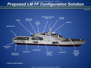
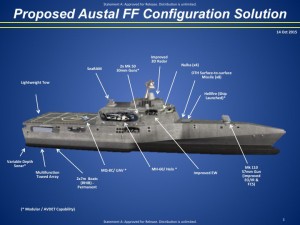
As you would expect, the new frigate proposals look a lot like the existing LCS designs. In 2016, the GAO noted that the Navy prioritized cost and schedule considerations over the fact that a “minor modified LCS” (i.e., the new frigate) was the least capable option considered.”  The competing designs for the new frigate are shown below (click on the graphic to enlarge):

LCS-program-slides-2016-05-18Source: U.S. NavyLCS-program-slides-2016-05-18-austalSource: U.S. Navy

GAO reported the following estimates for the cost of the new multi-mission frigate and its mission equipment:

  • Lead ship: $732 – 754 million
  • Average ship: $613 – 631 million
  • Average annual per-ship operating cost over a 25 year lifetime: $59 – 62 million

Note that the frigate lead ship cost estimate is less than the GAO’s estimated actual cost of an average LCS plus one mission module. Based on the vendor’s actual LCS cost control history, I’ll bet that the GAO’s frigate cost estimates are just the starting point for the cost growth curve.

To make room for the new frigate in the budget and in the current 308-ship fleet headcount limit, the Navy reduced the LCS buy to 32 vessels, and planed to order 20 new frigates from a single vendor. In December 2015, the Navy reduced the total quantity of LCS and frigates from 52 to 40. By mid-2016, Navy plans included only 26 LCS and 12 frigates.

2016 Top Ten Most Powerful Frigates in the World

To see what international counterparts the LCS and FF are up against, check out the January 2016 article, “Top Ten Most Powerful Frigates in the World,” which includes frigates typically in the 4,000 to 6,900 ton range (larger than LCS). You’ll find this at the following link:
https://defencyclopedia.com/2016/01/02/top-10-most-powerful-frigates-in-the-world/

There are no U.S. ships in this top 10.

So what do you think?

  • Are the single-mission LCSs really worth the Navy’s great investment in the LCS program?
  • Will the two-mission FFs give the Navy a world-class frigate that can operate independently in contested waters?
  • Would you want to serve aboard an LCS or FF when the fighting breaks out, or would you choose one of the more capable multi-mission international frigates?

Update: 9 January 2020

A 5 April 2019 article in The National Interest reported:

“The Pentagon Operational Test & Evaluation office’s review of the LCS fleet published back in January 2018 revealed alarming problems with both Freedom and Independence variants of the line, including: concerning issues with combat system elements like radar, limited anti-ship missile self-defense capabilities, and a distinct lack of redundancies for vital systems necessary to reduce the chance that “a single hit will result in loss of propulsion, combat capability, and the ability to control damage and restore system operation…..Neither LCS variant is survivable in high-intensity combat,” according to the report.”

The article’s link to the referenced 2018 Pentagon DOT&E report now results on a “404 – Page not found!” message on the DoD website. I’ve been unable to find that report elsewhere on the Internet.  I wonder why? See for yourself here:  https://nationalinterest.org/blog/buzz/no-battleship-littoral-combat-ship-might-be-navys-worst-warship-50882

I’d chalk the LCS program up as a huge failure, delivering unreliable, poorly-armed ships that do not yet have a meaningful, operational role in the U.S. Navy and have not been integrated as an element of a battle group.  I think others agree.  The defense bill signed by President Trump in December 2019 limits LCS fleet size and states that none of the authorized funds can be used to exceed “the total procurement quantity of 35 Littoral Combat Ships.” Do I hear an Amen?

For more information:

A lot of other resources are available on the Internet describing the LCS program, early LCS operations, the LCS-derived frigate program, and other international frigates programs. For more information, I recommend the following resources dating from 2016 to 2019:

  • “Littoral Combat Ship and Frigate: Delaying Planned Frigate Acquisition Would Enable Better-Informed Decisions, “ GAO-17-323, General Accounting Office, 18 April 2017:  https://www.gao.gov/products/GAO-17-323
  • “Storm-Tossed:  The Controversial Littoral Combat Ship,” Breaking Defense, November 2016.  The website Breaking Defense (http://breakingdefense.com) is an online magazine that offers defense industry news, analysis, debate, and videos. Their free eBook collects their coverage of the Navy’s LCS program.  You can get a copy at the following link:  http://info.breakingdefense.com/littoral-combat-ship-ebook
International Energy Agency (IEA) Assesses World Energy Trends

Peter Lobner

The IEA issued two important reports in late 2016, brief overviews of which are provided below.

World Energy Investment 2016 (WEI-2016)

In September 2016, the IEA issued their report, “World Energy Investment 2016,” which, they state, is intended to addresses the following key questions:

  • What was the level of investment in the global energy system in 2015? Which countries attracted the most capital?
  • What fuels and technologies received the most investment and which saw the biggest changes?
  • How is the low fuel price environment affecting spending in upstream oil and gas, renewables and energy efficiency? What does this mean for energy security?
  • Are current investment trends consistent with the transition to a low-carbon energy system?
  • How are technological progress, new business models and key policy drivers such as the Paris Climate Agreement reshaping investment?

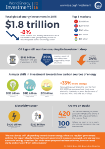
The following IEA graphic summarizes key findings in WEI-2016 (click on the graphic to enlarge):

WEI-2016

You can download the Executive Summary of WEI-2016 at the following link:
https://www.iea.org/newsroom/news/2016/september/world-energy-investment-2016.html

At this link, you also can order an individual copy of the complete report for a price (between €80 – €120).

You also can download a slide presentation on WEI 2016 at the following link:
https://csis-prod.s3.amazonaws.com/s3fs-public/event/161025_Laszlo_Varro_Investment_Slides_0.pdf

World Energy Outlook 2016 (WEO-2016)

The IEA issued their report, “World Energy Outlook 2016,” in November 2016. The report addresses the expected transformation of the global energy mix through 2040 as nations attempt to meet national commitments made in the Paris Agreement on climate change, which entered into force on 4 November 2016.

You can download the Executive Summary of WEO-2016 at the following link:
https://www.iea.org/newsroom/news/2016/november/world-energy-outlook-2016.html

At this link, you also can order an individual copy of the complete report for a price (between €120 – €180).

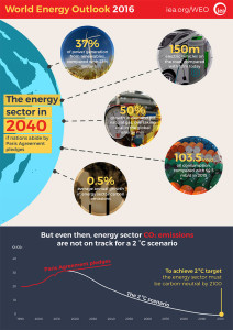
The following IEA graphic summarizes key findings in WEO-2016 (click on the graphic to enlarge):

WEO-2016

Climate Change and Nuclear Power

Peter Lobner

In September 2016, the International Atomic Energy Agency (IAEA) published a report entitled, “Climate Change and Nuclear Power 2016.” As described by the IAEA:

“This publication provides a comprehensive review of the potential role of nuclear power in mitigating global climate change and its contribution to other economic, environmental and social sustainability challenges.”

An important result documented in this report is a comparative analysis of the life cycle greenhouse gas (GHG) emissions for 10 electric power generating technologies. The IAEA authors note that:

“By comparing the GHG emissions of all existing and future energy technologies, this section (of the report) demonstrates that nuclear power provides energy services with very few GHG emissions and is justifiably considered a low carbon technology.

In order to make an adequate comparison, it is crucial to estimate and aggregate GHG emissions from all phases of the life cycle of each energy technology. Properly implemented life cycle assessments include upstream processes (extraction of construction materials, processing, manufacturing and power plant construction), operational processes (power plant operation and maintenance, fuel extraction, processing and transportation, and waste management), and downstream processes (dismantling structures, recycling reusable materials and waste disposal).”

The results of this comparative life cycle GHG analysis appear in Figure 5 of this report, which is reproduced below (click on the graphic to enlarge):

IAEA Climate Change & Nuclear Power

You can see that nuclear power has lower life cycle GHG emissions that all other generating technologies except hydro. It also is interesting to note how effective carbon dioxide capture and storage could be in reducing GHG emissions from fossil power plants.

You can download a pdf copy of this report for free on the IAEA website at the following link:

http://www-pub.iaea.org/books/iaeabooks/11090/Climate-Change-and-Nuclear-Power-2016

For a link to a similar 2015 report by The Brattle Group, see my post dated 8 July 2015, “New Report Quantifies the Value of Nuclear Power Plants to the U.S. Economy and Their Contribution to Limiting Greenhouse Gas (GHG) Emissions.”

It is noteworthy that the U.S. Environmental Protection Agency’s (EPA) Clean Power Plan (CPP), which was issued in 2015, fails to give appropriate credit to nuclear power as a clean power source. For more information on this matter see my post dated 2 July 2015,” EPA Clean Power Plan Proposed Rule Does Not Adequately Recognize the Role of Nuclear Power in Greenhouse Gas Reduction.”

In contrast to the EPA’s CPP, New York state has implemented a rational Clean Energy Standard (CES) that awards zero-emissions credits (ZEC) that favor all technologies that can meet specified emission standards. These credits are instrumental in restoring merchant nuclear power plants in New York to profitable operation and thereby minimizing the likelihood that the operating utilities will retire these nuclear plants early for financial reasons. For more on this subject, see my post dated 28 July 2016, “The Nuclear Renaissance is Over in the U.S.”  In that post, I noted that significant growth in the use of nuclear power will occur in Asia, with use in North America and Europe steady or declining as older nuclear power plants retire and fewer new nuclear plants are built to take their place.

An updated projection of worldwide use of nuclear power is available in the 2016 edition of the IAEA report, “Energy, Electricity and Nuclear Power Estimates for the Period up to 2050.” You can download a pdf copy of this report for free on the IAEA website at the following link:
http://www-pub.iaea.org/books/IAEABooks/11120/Energy-Electricity-and-Nuclear-Power-Estimates-for-the-Period-up-to-2050

Combining the information in the two IAEA reports described above, you can get a sense for what parts of the world will be making greater use of nuclear power as part of their strategies for reducing GHG emissions. It won’t be North America or Europe.