Category Archives: Astronomy

NuSTAR Provides a High-Resolution X-ray View of our Universe

Peter Lobner

In my 6 March 2016 post, “Remarkable Multispectral View of Our Milky Way Galaxy,” I briefly discussed several of the space-based observatories that are helping to develop a deeper understanding of our galaxy and the universe. One space-based observatory not mentioned in that post is the National Aeronautics and Space Administration (NASA) Nuclear Spectroscopic Telescope Array (NuSTAR) X-Ray observatory, which was launched on 13 June 2012 into a near equatorial, low Earth orbit. NASA describes the NuSTAR mission as follows:

“The NuSTAR mission has deployed the first orbiting telescopes to focus light in the high energy X-ray (6 – 79 keV) region of the electromagnetic spectrum. Our view of the universe in this spectral window has been limited because previous orbiting telescopes have not employed true focusing optics, but rather have used coded apertures that have intrinsically high backgrounds and limited sensitivity.

During a two-year primary mission phase, NuSTAR will map selected regions of the sky in order to:

1.  Take a census of collapsed stars and black holes of different sizes by surveying regions surrounding the center of own Milky Way Galaxy and performing deep observations of the extragalactic sky;

2.  Map recently-synthesized material in young supernova remnants to understand how stars explode and how elements are created; and

3.  Understand what powers relativistic jets of particles from the most extreme active galaxies hosting supermassive black holes.”

 The NuSTAR spacecraft is relatively small, with a payload mass of only 171 kg (377 lb). In it’s stowed configuration, this compact satellite was launched by an Orbital ATK Pegasus XL booster, which was carried aloft by the Stargazer L-1011 aircraft to approximately 40,000 feet over open ocean, where the booster was released and carried the small payload into orbit.

Orbital ATK L-1011 StargazerStargazer L-1011 dropping a Pegasus XL booster. Source: Orbital ATK

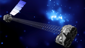
In orbit, the solar-powered NuSTAR extended to a total length of 10.9 meters (35.8 feet) in the orbital configuration shown below. The extended spacecraft gives the X-ray telescope a 10 meter (32.8 foot) focal length.

NuSTAR satelliteNuSTAR orbital configuration. Source: NASA / JPL – Caltech

NASA describes the NuSTAR X-Ray telescope as follows:

“The NuSTAR instrument consists of two co-aligned grazing incidence X-Ray telescopes (Wolter type I) with specially coated optics and newly developed detectors that extend sensitivity to higher energies as compared to previous missions such as NASA’a Chandra X-Ray Observatory launched in 1999 and the European Space Agency’s (ESA) XMM-Newton (aka High-throughput X-Ray Spectrometry Mission), also launched in 1999…….. The observatory will provide a combination of sensitivity, spatial, and spectral resolution factors of 10 to 100 improved over previous missions that have operated at these X-ray energies.”

The NASA NuSTAR mission website is at the following link:

https://www.nasa.gov/mission_pages/nustar/main/index.html

Some examples of NuSTAR findings posted on this website are summarized below.

X-ray emitting structures of galaxies identified

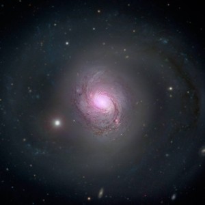
In the following composite image of Galaxy 1068, high-energy X-rays (shown in magenta) captured by NuSTAR are overlaid on visible-light images from both NASA’s Hubble Space Telescope and the Sloan Digital Sky Survey.

Galaxy 1068Galaxy 1068. Source: NASA/JPL-Caltech/Roma Tre Univ

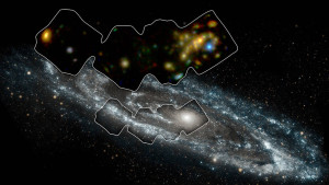
Below is a more detailed X-ray view of portion of the Andromeda galaxy (aka M31), which is the galaxy nearest to our Milky Way. On 5 January 2017, NASA reported:

“The space mission has observed 40 ‘X-ray binaries’ — intense sources of X-rays comprised of a black hole or neutron star that feeds off a stellar companion.

Andromeda is the only large spiral galaxy where we can see individual X-ray binaries and study them in detail in an environment like our own.”

In the following image, the portion of the Andromeda galaxy surveyed by NuSTAR is in the smaller outlined area. The larger outlined area toward the top of this image is the corresponding X-ray view of the surveyed area.

Andromeda galaxyAndromeda galaxy.  Source: NASA/JPL-Caltech/GSFC

NASA describes the following mechanism for X-ray binaries to generate the observed intense X-ray emissions:

“In X-ray binaries, one member is always a dead star or remnant formed from the explosion of what was once a star much more massive than the sun. Depending on the mass and other properties of the original giant star, the explosion may produce either a black hole or neutron star. Under the right circumstances, material from the companion star can “spill over” its outermost edges and then be caught by the gravity of the black hole or neutron star. As the material falls in, it is heated to blazingly high temperatures, releasing a huge amount of X-rays.”

You can read more on this NuStar discovery at the following link:

https://www.nasa.gov/feature/jpl/Andromeda-Galaxy-Scanned-with-High-Energy-X-ray-Vision

Composition of supernova remnants determined

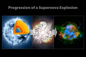
Cassiopeia A is within our Milky Way, about 11,000 light-years from Earth. The following NASA three-panel chart shows Cassiopeia A originally as an iron-core star. After going supernova, Cassiopeia A scattered its outer layers, which have distributed into the diffuse structure we see today, known as the supernova remnant. The image in the right-hand panel is a composite X-ray image of the supernova remnant from both the Chandra X-ray Observatory and NuStar.

Cassiopeia ASource: NASA/CXC/SAO/JPL-Caltech

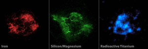
In the following three-panel chart, the composite image (above, right) is unfolded into its components. Red shows iron and green shows both silicon and magnesium, as seen by the Chandra X-ray Observatory. Blue shows radioactive titanium-44, as mapped by NuSTAR.

 Cassiopeia A componentsSource: NASA/JPL-Caltech/CXC/SAO

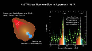
Supernova 1987A is about 168,000 light-years from Earth in the Large Magellanic Cloud. As shown below, NuSTAR also observed titanium in this supernova remnant.

SN 1987A titaniumSource: NASA/JPL-Caltech/UC Berkeley

These observations are providing new insights into how massive stars explode into supernovae.

Severe Space Weather Events Will Challenge Critical Infrastructure Systems on Earth

Peter Lobner

What is space weather?

Space weather is determined largely by the variable effects of the Sun on the Earth’s magnetosphere. The basic geometry of this relationship is shown in the following diagram, with the solar wind always impinging on the Earth’s magnetic field and transferring energy into the magnetosphere.  Normally, the solar wind does not change rapidly, and Earth’s space weather is relatively benign. However, sudden disturbances on the Sun produce solar flares and coronal holes that can cause significant, rapid variations in Earth’s space weather.
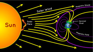
auroradiagramSource: http://scijinks.jpl.nasa.gov/aurora/

A solar storm, or geomagnetic storm, typically is associated with a large-scale magnetic eruption on the Sun’s surface that initiates a solar flare and an associated coronal mass ejection (CME). A CME is a giant cloud of electrified gas (solar plasma.) that is cast outward from the Sun and may intersect Earth’s orbit. The solar flare also releases a burst of radiation in the form of solar X-rays and protons.

The solar X-rays travel at the speed of light, arriving at Earth’s orbit in 8 minutes and 20 seconds. Solar protons travel at up to 1/3 the speed of light and take about 30 minutes to reach Earth’s orbit. NOAA reports that CMEs typically travel at a speed of about 300 kilometers per second, but can be as slow as 100 kilometers per second. The CMEs typically take 3 to 5 days to reach the Earth and can take as long as 24 to 36 hours to pass over the Earth, once the leading edge has arrived.

If the Earth is in the path, the X-rays will impinge on the Sun side of the Earth, while charged particles will travel along magnetic field lines and enter Earth’s atmosphere near the north and south poles. The passing CME will transfer energy into the magnetosphere.

Solar storms also may be the result of high-speed solar wind streams (HSS) that emanate from solar coronal holes (an area of the Sun’s corona with a weak magnetic field) with speeds up to 3,000 kilometers per second. The HSS overtakes the slower solar wind, creating turbulent regions (co-rotating interaction regions, CIR) that can reach the Earth’s orbit in as short as 18 hours. A CIR can deposit as much energy into Earth’s magnetosphere as a CME, but over a longer period of time, up to several days.

Solar storms can have significant effects on critical infrastructure systems on Earth, including airborne and space borne systems. The following diagram highlights some of these vulnerabilities.
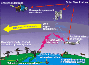
Canada Geomagnetic-Storms-effects-space-weather-technologyEffects of Space Weather on Modern Technology. Source: SpaceWeather.gc.ca

Characterizing space weather

The U.S. National Oceanic and Atmospheric Administration (NOAA) Space Weather Prediction Center (SWPC) uses the following three scales to characterize space weather:

  • Geomagnetic storms (G): intensity measured by the “planetary geomagnetic disturbance index”, Kp, also known as the Geomagnetic Storm or G-Scale
  • Solar radiation storms (S): intensity measured by the flux level of ≥ 10 MeV solar protons at GEOS (Geostationary Operational Environmental Satellite) satellites, which are in synchronous orbit around the Earth.
  • Radio blackouts (R): intensity measured by flux level of solar X-rays at GEOS satellites.

Another metric of space weather is the Disturbance Storm Time (Dst) index, which is a measure of the strength of a ring current around Earth caused by solar protons and electrons. A negative Dst value means that Earth’s magnetic field is weakened, which is the case during solar storms.

A single solar disturbance (a CME or a CIR) will affect all of the NOAA scales and Dst to some degree.

As shown in the following NOAA table (click on table to enlarge), the G-scale describes the infrastructure effects that can be experienced for five levels of geomagnetic storm severity. At the higher levels of the scale, significant infrastructure outages and damage are possible.
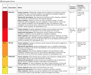
NOAA geomag storm scale

There are similar tables for Solar Radiation Storms and Radio Blackouts on the NOAA SWPC website at the following link:

http://www.swpc.noaa.gov/noaa-scales-explanation

Another source for space weather information is the spaceweather.com website, which contains some information not found on the NOAA SWPC website. For example, this website includes a report of radiation levels in the atmosphere at aviation altitudes and higher in the stratosphere. In the following chart, “dose rates are expressed as multiples of sea level. For instance, we see that boarding a plane that flies at 25,000 feet exposes passengers to dose rates ~10x higher than sea level. At 40,000 feet, the multiplier is closer to 50x.”
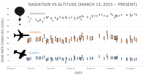
 spaceweather rad levelsSource: spaceweather.com

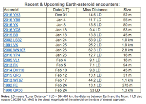
You’ll also find a report of recent and upcoming near-Earth asteroids on the spaceweather.com website. This definitely broadens the meaning of “space weather.” As you can seen the in the following table, no close encounters are predicted over the next two months.
spaceweather NEOs

In summary, the effects of a solar storm may include:

  • Interference with or damage to spacecraft electronics: induced currents and/or energetic particles may have temporary or permanent effects on satellite systems
  • Navigation satellite (GPS, GLONASS and Galileo) UHF / SHF signal scintillation (interference)
  • Increased drag on low Earth orbiting satellites: During storms, currents and energetic particles in the ionosphere add energy in the form of heat that can increase the density of the upper atmosphere, causing extra drag on satellites in low-earth orbit
  • High-frequency (HF) radio communications and low-frequency (LF) radio navigation system interference or signal blackout
  • Geomagnetically induced currents (GICs) in long conductors can trip protective devices and may damage associated hardware and control equipment in electric power transmission and distribution systems, pipelines, and other cable systems on land or undersea.
  • Higher radiation levels experienced by crew & passengers flying at high latitudes in high-altitude aircraft or in spacecraft.

For additional information, you can download the document, “Space Weather – Effects on Technology,” from the Space Weather Canada website at the following link:

http://ftp.maps.canada.ca/pub/nrcan_rncan/publications/ess_sst/292/292124/gid_292124.pdf

Historical major solar storms

The largest recorded geomagnetic storm, known as the Carrington Event or the Solar Storm of 1859, occurred on 1 – 2 September 1859. Effects included:

  • Induced currents in long telegraph wires, interrupting service worldwide, with a few reports of shocks to operators and fires.
  • Aurorea seen as far south as Hawaii, Mexico, Caribbean and Italy.

This event is named after Richard Carrington, the solar astronomer who witnessed the event through his private observatory telescope and sketched the Sun’s sunspots during the event. In 1859, no electric power transmission and distribution system, pipeline, or cable system infrastructure existed, so it’s a bit difficult to appreciate the impact that a Carrington-class event would have on our modern technological infrastructure.

A large geomagnetic storm in March 1989 has been attributed as the cause of the rapid collapse of the Hydro-Quebec power grid as induced voltages caused protective relays to trip, resulting in a cascading failure of the power grid. This event left six million people without electricity for nine hours.

A large solar storm on 23 July 2012, believed to be similar in magnitude to the Carrington Event, was detected by the STEREO-A (Solar TErrestrial RElations Observatory) spacecraft, but the storm passed Earth’s orbit without striking the Earth. STEREO-A and its companion, STEREO-B, are in heliocentric orbits at approximately the same distance from the Sun as Earth, but displaced ahead and behind the Earth to provide a stereoscopic view of the Sun.

You’ll find a historical timeline of solar storms, from the 28 August 1859 Carrington Event to the 29 October 2003 Halloween Storm on the Space Weather website at the following link:

http://www.solarstorms.org/SRefStorms.html

Risk from future solar storms

A 2013 risk assessment by the insurance firm Lloyd’s and consultant engineering firm Atmospheric and Environmental Research (AER) examined the impact of solar storms on North America’s electric grid.

electrical-power-transmission-lines-united-states-useiaU.S. electric power transmission grid. Source: EIA

Here is a summary of the key findings of this risk assessment:

  • A Carrington-level extreme geomagnetic storm is almost inevitable in the future. Historical auroral records suggest a return period of 50 years for Quebec-level (1989) storms and 150 years for very extreme storms, such as the Carrington Event (1859).
  • The risk of intense geomagnetic storms is elevated near the peak of the each 11-year solar cycle, which peaked in 2015.
  • As North American electric infrastructure ages and we become more dependent on electricity, the risk of a catastrophic outage increases with each peak of the solar cycle.
  • Weighted by population, the highest risk of storm-induced power outages in the U.S. is along the Atlantic corridor between Washington D.C. and New York City.
  • The total U.S. population at risk of extended power outage from a Carrington-level storm is between 20-40 million, with durations from 16 days to 1-2 years.
  • Storms weaker than Carrington-level could result in a small number of damaged transformers, but the potential damage in densely populated regions along the Atlantic coast is significant.
  • A severe space weather event that causes major disruption of the electricity network in the U.S. could have major implications for the insurance industry.

The Lloyds report identifies the following relative risk factors for electric power transmission and distribution systems:

  • Magnetic latitude: Higher north and south “corrected” magnetic latitudes are more strongly affected (“corrected” because the magnetic North and South poles are not at the geographic poles). The effects of a major storm can extend to mid-latitudes.
  • Ground conductivity (down to a depth of several hundred meters): Geomagnetic storm effects on grounded infrastructure depend on local ground conductivity, which varies significantly around the U.S.
  • Coast effect: Grounded systems along the coast are affected by currents induced in highly-conductive seawater.
  • Line length and rating: Induced current increases with line length and the kV rating (size) of the line.
  • Transformer design: Lloyds noted that extra-high voltage (EHV) transformers (> 500 kV) used in electrical transmission systems are single-phase transformers. As a class, these are more vulnerable to internal heating than three-phase transformers for the same level of geomagnetically induced current.

Combining these risk factors on a county-by-county basis produced the following relative risk map for the northeast U.S., from New York City to Maine. The relative risk scale covers a range of 1000. The Lloyd’s report states, “This means that for some counties, the chance of an average transformer experiencing a damaging geomagnetically induced current is more than 1000 times that risk in the lowest risk county.”

Lloyds relative risk Relative risk of power outage from geomagnetic storm. Source: Lloyd’s

You can download the complete Lloyd risk assessment at the following link:

https://www.lloyds.com/news-and-insight/risk-insight/library/natural-environment/solar-storm

In May 2013, the United States Federal Energy Regulatory Commission issued a directive to the North American Electric Reliability Corporation (NERC) to develop reliability standards to address the impact of geomagnetic disturbances on the U.S. electrical transmission system. One part of that effort is to accurately characterize geomagnetic induction hazards in the U.S. The most recent results were reported in the 19 September 2016, a paper by J. Love et al., “Geoelectric hazard maps for the continental United States.” In this report the authors characterize geography and surface impedance of many sites in the U.S. and explain how these characteristics contribute to regional differences in geoelectric risk. Key findings are:

“As a result of the combination of geographic differences in geomagnetic activity and Earth surface impedance, once-per-century geoelectric amplitudes span more than 2 orders of magnitude (factor of 100) and are an intricate function of location.”

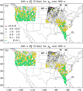
“Within regions of the United States where a magnetotelluric survey was completed, Minnesota (MN) and Wisconsin (WI) have some of the highest geoelectric hazards, while Florida (FL) has some of the lowest.”

“Across the northern Midwest …..once-per-century geoelectric amplitudes exceed the 2 V/km that Boteler ……has inferred was responsible for bringing down the Hydro-Québec electric-power grid in Canada in March 1989.”

The following maps from this paper show maximum once-per-century geoelectric exceedances at EarthScope and U.S. Geological Survey magnetotelluric survey sites for geomagnetic induction (a) north-south and (b) east-west. In these maps, you can the areas of the upper Midwest that have the highest risk.
JLove Sep2016_grl54980-fig-0004

The complete paper is available online at the following link:

http://onlinelibrary.wiley.com/doi/10.1002/2016GL070469/full

Is the U.S. prepared for a severe solar storm?

The quick answer, “No.” The possibility of a long-duration, continental-scale electric power outage exists. Think about all of the systems and services that are dependent on electric power in your home and your community, including communications, water supply, fuel supply, transportation, navigation, food and commodity distribution, healthcare, schools, industry, and public safety / emergency response. Then extrapolate that statewide and nationwide.

In October 2015, the National Science and Technology Council issued the, “National Space Weather Action Plan,” with the following stated goals:

  • Establish benchmarks for space-weather events: induced geo-electric fields), ionizing radiation, ionospheric disturbances, solar radio bursts, and upper atmospheric expansion
  • Enhance response and recovery capabilities, including preparation of an “All-Hazards Power Outage Response and Recovery Plan.
  • Improve protection and mitigation efforts
  • Improve assessment, modeling, and prediction of impacts on critical infrastructure
  • Improve space weather services through advancing understanding and forecasting
  • Increase international cooperation, including policy-level acknowledgement that space weather is a global challenge

The Action Plan concludes:

“The activities outlined in this Action Plan represent a merging of national and homeland security concerns with scientific interests. This effort is only the first step. The Federal Government alone cannot effectively prepare the Nation for space weather; significant effort must go into engaging the broader community. Space weather poses a significant and complex risk to critical technology and infrastructure, and has the potential to cause substantial economic harm. This Action Plan provides a road map for a collaborative and Federally-coordinated approach to developing effective policies, practices, and procedures for decreasing the Nation’s vulnerabilities.”

You can download the Action Plan at the following link:

https://www.whitehouse.gov/sites/default/files/microsites/ostp/final_nationalspaceweatheractionplan_20151028.pdf

To supplement this Action Plan, on 13 October 2016, the President issued an Executive Order entitled, “Coordinating Efforts to Prepare the Nation for Space Weather Events,” which you can read at the following link:

https://www.whitehouse.gov/the-press-office/2016/10/13/executive-order-coordinating-efforts-prepare-nation-space-weather-events

Implementation of this Executive Order includes the following provision (Section 5):

Within 120 days of the date of this order, the Secretary of Energy, in consultation with the Secretary of Homeland Security, shall develop a plan to test and evaluate available devices that mitigate the effects of geomagnetic disturbances on the electrical power grid through the development of a pilot program that deploys such devices, in situ, in the electrical power grid. After the development of the plan, the Secretary shall implement the plan in collaboration with industry.”

So, steps are being taken to better understand the potential scope of the space weather problems and to initiate long-term efforts to mitigate their effects. Developing a robust national mitigation capability for severe space weather events will take several decades. In the meantime, the nation and the whole world remain very vulnerable to sever space weather.

Today’s space weather forecast

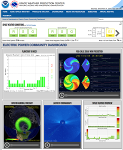
Based on the Electric Power Community Dashboard from NOAA’s Space Weather Prediction Center, it looks like we have mild space weather on 31 December 2016. All three key indices are green: R (radio blackouts), S (solar radiation storms), and G (geomagnetic storms). That’s be a good way to start the New Year.
NOAA space weather 31Dec2016

See your NOAA space weather forecast at:

http://www.swpc.noaa.gov/communities/electric-power-community-dashboard

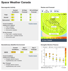
Natural Resources Canada also forecasts mild space weather for the far north.
Canada space weather 31Dec2016You can see the Canadian space weather forecast at the following link:

http://www.spaceweather.gc.ca/index-en.php

4 January 2017 Update: G1 Geomagnetic Storm Approaching Earth

On 2 January, 2017, NOAA’s Space Weather Prediction Center reported that NASA’s STEREO-A spacecraft encountered a 700 kilometer per second HSS that will be pointed at Earth in a couple of days.

“A G1 (Minor) geomagnetic storm watch is in effect for 4 and 5 January, 2017. A recurrent, polar connected, negative polarity coronal hole high-speed stream (CH HSS) is anticipated to rotate into an Earth-influential position by 4 January. Elevated solar wind speeds and a disturbed interplanetary magnetic field (IMF) are forecast due to the CH HSS. These conditions are likely to produce isolated periods of G1 storming beginning late on 4 January and continuing into 5 January. Continue to check our SWPC website for updated information and forecasts.”

The coronal hole is visible as the darker regions in the following image from NASA’s Solar Dynamics Observatory (SDO) satellite, which is in a geosynchronous orbit around Earth.
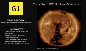
NOAA SWPC 4Jan2017Source: NOAA SWPC

SDO has been observing the Sun since 2010 with a set of three instruments:

  • Helioseismic and Magnetic Imager (HMI)
  • Extreme Ultraviolet Variability Experiment (EVE)
  • Atmospheric Imaging Assembly (AIA)

The above image of the coronal hole was made by SDO’s AIA. Another view, from the spaceweather.com website, provides a clearer depiction of the size and shape of the coronal hole creating the current G1 storm.
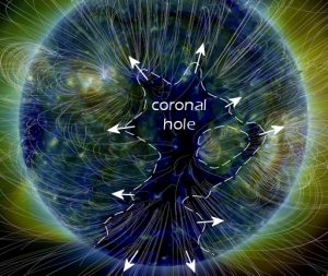
spaceweather coronal holeSource: spaceweather.com

You’ll find more information on the SDO satellite and mission on the NASA website at the following link:

https://sdo.gsfc.nasa.gov/mission/spacecraft.php

Emergent Gravity Theory Passes its First Test

Peter Lobner

In 2010, Prof. Erik Verlinde, University of Amsterdam, Delta Institute for Theoretical Physics, published the paper, “The Origin of Gravity and the Laws of Newton.” In this paper, the author concluded:

 “The results of this paper suggest gravity arises as an entropic force, once space and time themselves have emerged. If the gravity and space time can indeed be explained as emergent phenomena, this should have important implications for many areas in which gravity plays a central role. It would be especially interesting to investigate the consequences for cosmology. For instance, the way redshifts arise from entropy gradients could lead to many new insights.

The derivation of the Einstein equations presented in this paper is analogous to previous works, in particular [the 1995 paper by T. Jacobson, ‘Thermodynamics of space-time: The Einstein equation of state.’]. Also other authors have proposed that gravity has an entropic or thermodynamic origin, see for instance [the paper by T. Padmanabhan, ‘Thermodynamical Aspects of Gravity: New insights.’]. But we have added an important element that is new. Instead of only focusing on the equations that govern the gravitational field, we uncovered what is the origin of force and inertia in a context in which space is emerging. We identified a cause, a mechanism, for gravity. It is driven by differences in entropy, in whatever way defined, and a consequence of the statistical averaged random dynamics at the microscopic level. The reason why gravity has to keep track of energies as well as entropy differences is now clear. It has to, because this is what causes motion!”

You can download Prof. Verlinde’s 2010 paper at the following link:

https://arxiv.org/pdf/1001.0785.pdf

On 8 November 2016, Delta Institute announced that Prof. Verlinde had published a new research paper, “Emergent Gravity and the Dark Universe,” expanding on his previous work. You can read this announcement and see a short video by Prof. Verlinde on the Delta Institute website at the following link:

http://www.d-itp.nl/news/list/list/content/folder/press-releases/2016/11/new-theory-of-gravity-might-explain-dark-matter.html

You can download this new paper at the following link:

https://arxiv.org/abs/1611.02269

I found it helpful to start with Section 8, Discussion and Outlook, which is the closest you will find to a layman’s description of the theory.

On the Physics.org website, a short 8 November 2016 article, “New Theory of Gravity Might Explain Dark Matter,” provides a good synopsis of Verlinde’s emergent gravity theory:

“According to Verlinde, gravity is not a fundamental force of nature, but an emergent phenomenon. In the same way that temperature arises from the movement of microscopic particles, gravity emerges from the changes of fundamental bits of information, stored in the very structure of spacetime……

According to Erik Verlinde, there is no need to add a mysterious dark matter particle to the theory……Verlinde shows how his theory of gravity accurately predicts the velocities by which the stars rotate around the center of the Milky Way, as well as the motion of stars inside other galaxies.

One of the ingredients in Verlinde’s theory is an adaptation of the holographic principle, introduced by his tutor Gerard ‘t Hooft (Nobel Prize 1999, Utrecht University) and Leonard Susskind (Stanford University). According to the holographic principle, all the information in the entire universe can be described on a giant imaginary sphere around it. Verlinde now shows that this idea is not quite correct—part of the information in our universe is contained in space itself.

This extra information is required to describe that other dark component of the universe: Dark energy, which is believed to be responsible for the accelerated expansion of the universe. Investigating the effects of this additional information on ordinary matter, Verlinde comes to a stunning conclusion. Whereas ordinary gravity can be encoded using the information on the imaginary sphere around the universe, as he showed in his 2010 work, the result of the additional information in the bulk of space is a force that nicely matches that attributed to dark matter.”

Read the full Physics.org article at the following link:

http://phys.org/news/2016-11-theory-gravity-dark.html#jCp

On 12 December 2016, a team from Leiden Observatory in The Netherlands reported favorable results of the first test of the emergent gravity theory. Their paper, “First Test of Verlinde’s Theory of Emergent Gravity Using Weak Gravitational Lensing Measurements,” was published in the Monthly Notices of the Royal Astronomical Society. The complete paper is available at the following link:

http://mnras.oxfordjournals.org/content/early/2016/12/09/mnras.stw3192

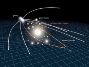
An example of a gravitational lens is shown in the following diagram.

Gravitational-lensing-galaxyApril12_2010-1024x768-e1481555047928 Source: NASA, ESA & L. Calça

As seen from the Earth, the light from the galaxy at the left is bent by the gravitational forces of the galactic cluster in the center, much like light passing though an optical lens.

The Leiden Observatory authors reported:

“We find that the prediction from EG, despite requiring no free parameters, is in good agreement with the observed galaxy-galaxy lensing profiles in four different stellar mass bins. Although this performance is remarkable, this study is only a first step. Further advancements on both the theoretical framework and observational tests of EG are needed before it can be considered a fully developed and solidly tested theory.”

These are exciting times! As noted in the Physics.org article, “We might be standing on the brink of a new scientific revolution that will radically change our views on the very nature of space, time and gravity.”

Atacama Large Millimeter / submillimeter Array (ALMA) Provides a Unique Window on the Universe

Peter Lobner

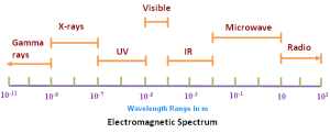
The Atacama Large Millimeter / submillimeter Array (ALMA) is a single telescope composed of 66 high-precision, 12-meter antennas. ALMA operates at wavelengths of 0.3 to 9.6 millimeters. As shown in the following chart, this puts ALMAs observing range around the boundary between microwave and infrared.

wavelength-spectrum1Source: physics.tutorvista.com

This enables ALMA’s users to examine “cold” regions of the universe, which are optically dark but radiate brightly in the millimeter / submillimeter portions of the electromagnetic spectrum. In that frequency range, ALMA is a complete astronomical imaging and spectroscopic instrument with a resolution better than the Hubble Space Telescope.

The ALMA Array Operations Site (AOS) is located on the Chajnantor plateau (which in the local Atacameño language, Kunza, means “place of departure”), at an elevation of about 5,000 meters (16,400 feet) above sea level in northern Chile.

ALMA_AOSView of the AOS. Source: ESO

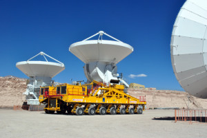
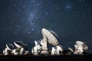
On 30 September 2013 the last of the 66 antennas, each of which weighs more than 100 tons, was delivered to the AOS on the giant transporter named Otto (one of two available for the task) and handed over to the ALMA Observatory. The 12 meter antennas have reconfigurable baselines ranging from 15 meters to 18 km. Depending on what is being observed, the transporters can move ALMA antennas to establish the desired array. The transporters carry power generators to maintain the cryogenic systems needed to ensure that the antenna continues functioning during transport.

ALMA_antenna on transporterSource: ESOalma_antennas_nrao04bSource: ESO

ALMA is managed by an international partnership  of the European Southern Observatory (ESO), the U.S. National Science Foundation (NSF) and the National Institutes of Natural Sciences (NINS) of Japan, together with NRC (Canada), NSC and ASIAA (Taiwan), and KASI (Republic of Korea), in cooperation with the Republic of Chile.

The ALMA telescope is operated from the Operations Support Facilities (OSF), which is located at a considerable distance from the telescope at an elevation of about 2,900 meters (9,500 feet). The OSF also served as the Assembly, Integration, Verification, and Commissioning (AIVC) station for all the antennas and other high technology equipment before they were moved to the AOS.

The ALMA website is at the following link:

http://www.almaobservatory.org

You’ll find many downloadable ALMA-related documents on the Publications tab of this website. A good overview of the ALMA telescope and the design of the individual antennas is available at:

http://www.almaobservatory.org/images/pdfs/alma_brochure_explore_2007.pdf

ALMA press releases, with details of on many of interesting observations being made at the observatory are at the following link:

http://www.almaobservatory.org/en/press-room/press-releases

An example of the type of remarkable observations being made with ALMA is in the 16 July 2016 press release, ALMA Observes First Protoplanetary Water Snow Line Thanks to Stellar Outburst.”

“This line marks where the temperature in the disk surrounding a young star drops sufficiently low for snow to form. A dramatic increase in the brightness of the young star V883 Orionis flash heated the inner portion of the disk, pushing the water snow line out to a far greater distance than is normal for a protostar, and making it possible to observe it for the first time.”

ALMA was looking in the right place at the right time. An artist’s impression of the water-snow line around V883 Orionis is shown in the ESO image below.

eso1626aCredit: A. Angelich (NRAO/AUI/NSF)/ALMA (ESO/NAOJ/NRAO)

You can read this ALMA press release and view a short video simulation of the event at the following link:

http://www.eso.org/public/usa/news/eso1626/

No doubt ALMA’s unique capabilities will continue to expand our knowledge of the universe in the millimeter / submillimeter portions of the electromagnetic spectrum. In collaboration with great land-based and space-based observatories operating in other portions of the spectrum, ALMA will help create a more comprehensive understanding of our universe. See my 6 March 2016 post, Remarkable Multispectral View of Our Milky Way Galaxy,” to see how different a portion of the night sky can look in different portions of the electromagnetic spectrum.

The Universe is Isotropic

Peter Lobner, Updated 12 January 2021

The concepts of up and down appear to be relatively local conventions that can be applied at the levels of subatomic particles, planets and galaxies. However, the universe as a whole apparently does not have a preferred direction that would allow the concepts of up and down to be applied at such a grand scale.

A 7 September 2016 article entitled, “It’s official: You’re lost in a directionless universe,” by Adrian Cho, provides an overview of research that demonstrates, with a high level of confidence, that the universe is isotropic. The research was based on data from the Planck space observatory. In this article, Cho notes:

“Now, one team of cosmologists has used the oldest radiation there is, the afterglow of the big bang, or the cosmic microwave background (CMB), to show that the universe is “isotropic,” or the same no matter which way you look: There is no spin axis or any other special direction in space. In fact, they estimate that there is only a one-in-121,000 chance of a preferred direction—the best evidence yet for an isotropic universe. That finding should provide some comfort for cosmologists, whose standard model of the evolution of the universe rests on an assumption of such uniformity.”

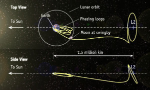
The European Space Agency (ESA) developed the Planck space observatory to map the CMB in microwave and infrared frequencies at unprecedented levels of detail. Planck was launched on 14 May 2009 and was placed in a Lissajous orbit around the L2 Lagrange point, which is 1,500,000 km (930,000 miles) directly behind the Earth. L2 is a quiet place, with the Earth shielding Planck from noise from the Sun. The approximate geometry of the Earth-Moon-Sun system and a representative spacecraft trajectory (not Planck, specifically) to the L2 Lagrange point is shown in the following figure.

Lissajous orbit L2Source: Abestrobi / Wikimedia Commons

The Planck space observatory entered service on 3 July 2009. At the end of its service life, Planck departed its valuable position at L2, was placed in a heliocentric orbit, and was deactivated on 23 October 2013. During more than four years in service, Planck performed its CBM mapping mission with much greater resolution than NASA’s Wilkinson Microwave Anisotropy Probe (WMAP), which operated from 2001 to 2010.  Planck was designed to map the CMB with an angular resolution of 5-10 arc minutes and a sensitivity of a millionth of a degree.

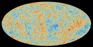
One key result of the Planck mission is the all-sky survey shown below.

Planck all-sky survey 2013 CBM temperature map shows anisotropies in the temperature of the CMB at the full resolution obtained by Planck. Source: ESA / Planck Collaboration
ESA characterizes this map as follows:

“The CMB is a snapshot of the oldest light in our Universe, imprinted on the sky when the Universe was just 380,000 years old. It shows tiny temperature fluctuations that correspond to regions of slightly different densities, representing the seeds of all future structure: the stars and galaxies of today.”

The researchers who reported that the universe was isotropic noted that an anisotropic universe would leave telltale patterns in the CMB. However, these researchers found that the actual CMB shows only random noise and no signs of such patterns.

The researchers who reported that the universe was isotropic noted that an anisotropic universe would leave telltale patterns in the CMB.  However, these researchers found that the actual CMB shows only random noise and no signs of such patterns.

In 2015, the ESA / Planck Collaboration used CMB data to estimate the age of the universe at 13.813 ± 0.038 billion years.  This was lightly higher than, but within the uncertainty band of, an estimate derived in 2012 from nine years of data from NASA’s Wilkinson Microwave Anisotropy Probe (WMAP) spacecraft.

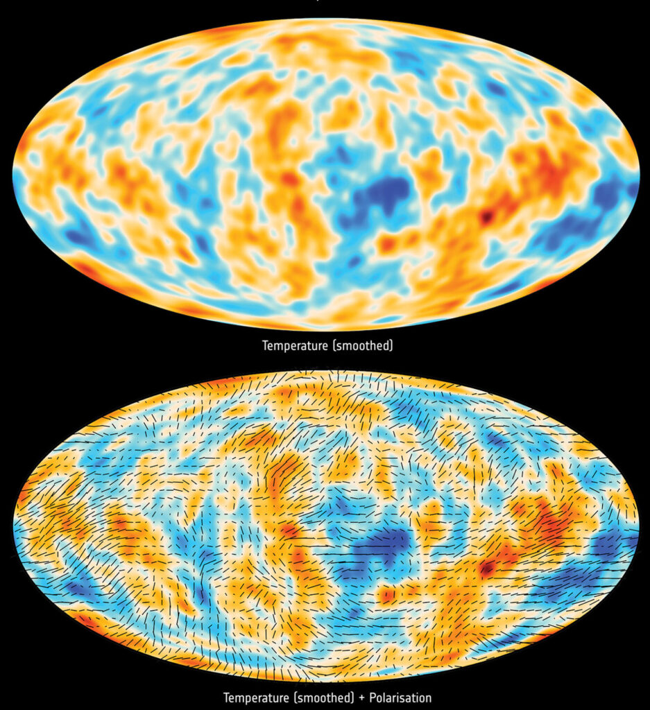
In July 2018, the ESA / Planck Collaboration published the “Planck Legacy” release of their results, which included the following two additional CBM sky survey maps.

Planck all-sky survey 2013 CBM smoothed temperature map (top) and smoothed temperature + polarization map (bottom). Source: ESA / Planck Collaboration

The ESA/Planck Collaboration described these two new maps as follows:

  • (In the top map), “the temperature anisotropies have been filtered to show mostly the signal detected on scales around 5º on the sky. The lower view shows the filtered temperature anisotropies with an added indication of the direction of the polarized fraction of the CMB.”
  • “A small fraction of the CMB is polarized – it vibrates in a preferred direction. This is a result of the last encounter of this light with electrons, just before starting its cosmic journey. For this reason, the polarization of the CMB retains information about the distribution of matter in the early Universe, and its pattern on the sky follows that of the tiny fluctuations observed in the temperature of the CMB” (in the 2013 map, above).

Using Planck CMB data, the ESA / Planck Collaboration team has estimated the value of the Hubble constant. Their latest estimate, in 2018, was 67.4 km / second / megaparsec with an uncertainty of less than 1%.  This is lower than the value derived from astrophysical measurements: 73.5 km / second / megaparsec with an uncertainty of 2%.
You’ll find more details on the Planck mission and scientific results on the ESA’s website at the following link: http://www.esa.int/Our_Activities/Space_Science/Planck

For more information:

Simulating Extreme Spacetimes

Peter Lobner

Thanks to Dave Groce for sending me the following link to the Caltech-Cornell Numerical Relativity collaboration; Simulating eXtreme Spacetimes (SXS):

http://www.black-holes.org

Caltech SXSSource: SXS

From the actual website (not the image above), click on the yellow “Admit One” ticket and you’re on your way.

Under the “Movies” tab, you’ll find many video simulations that help visualizes a range of interactions between two black holes and between a black hole and a neutron star. Following is a direct link:

http://www.black-holes.org/explore/movies

A movie visualizing GW150914, the first ever gravitational wave detection on 14 September 2015, is at the following SXS link:

https://www.black-holes.org/gw150914

At the above link, you also can listen to the sound of the GW150914 “in-spiral” event (two black holes spiraling in on each other).  You can read more about the detection of GW150914 in my 11 February 2016 post.

On the “Sounds” tab on the SXS website, you’ll find that different types of major cosmic events are expected to emit gravitational waves with waveforms that will help characterize the original event. You can listen to the expected sounds from a variety of extreme cosmic events at the following SXS link:

http://www.black-holes.org/explore/sounds

Have fun exploring SXS.

Synthetic Aperture Radar (SAR) and Inverse SAR (ISAR) Enable an Amazing Range of Remote Sensing Applications

Peter Lobner

SAR Basics

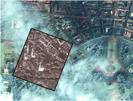
Synthetic Aperture Radar (SAR) is an imaging radar that operates at microwave frequencies and can “see” through clouds, smoke and foliage to reveal detailed images of the surface below in all weather conditions. Below is a SAR image superimposed on an optical image with clouds, showing how a SAR image can reveal surface details that cannot be seen in the optical image.

Example SAR imageSource: Cassidian radar, Eurimage optical

SAR systems usually are carried on airborne or space-based platforms, including manned aircraft, drones, and military and civilian satellites. Doppler shifts from the motion of the radar relative to the ground are used to electronically synthesize a longer antenna, where the synthetic length (L) of the aperture is equal to: L = v x t, where “v” is the relative velocity of the platform and “t” is the time period of observation. Depending on the altitude of the platform, “L” can be quite long. The time-multiplexed return signals from the radar antenna are electronically recombined to produce the desired images in real-time or post-processed later.

SAR principle

Source: Christian Wolff, http://www.radartutorial.eu/20.airborne/pic/sar_principle.print.png

This principle of SAR operation was first identified in 1951 by Carl Wiley and patented in 1954 as “Simultaneous Buildup Doppler.”

SAR Applications

There are many SAR applications, so I’ll just highlight a few.

Boeing E-8 JSTARS: The Joint Surveillance Target Attack Radar System is an airborne battle management, command and control, intelligence, surveillance and reconnaissance platform, the prototypes of which were first deployed by the U.S. Air Force during the 1991 Gulf War (Operation Desert Storm). The E-8 platform is a modified Boeing 707 with a 27 foot (8 meter) long, canoe-shaped radome under the forward fuselage that houses a 24 foot (7.3 meters) long, side-looking, multi-mode, phased array antenna that includes a SAR mode of operation. The USAF reports that this radar has a field of view of up to 120-degrees, covering nearly 19,305 square miles (50,000 square kilometers).

E-8 JSTARSSource: USAF

Lockheed SR-71: This Mach 3 high-altitude reconnaissance jet carried the Advanced Synthetic Aperture Radar System (ASARS-1) in its nose. ASARS-1 had a claimed 1 inch resolution in spot mode at a range of 25 to 85 nautical miles either side of the flight path.  This SAR also could map 20 to 100 nautical mile swaths on either side of the aircraft with lesser resolution.

SR-71Source: http://www.wvi.com/~sr71webmaster/sr_sensors_pg2.htm

Northrop RQ-4 Global Hawk: This is a large, multi-purpose, unmanned aerial vehicle (UAV) that can simultaneously carry out electro-optical, infrared, and synthetic aperture radar surveillance as well as high and low band signal intelligence gathering.

Global HawkSource: USAF

Below is a representative RQ-4 2-D SAR image that has been highlighted to show passable and impassable roads after severe hurricane damage in Haiti. This is an example of how SAR data can be used to support emergency management.

Global Hawk Haiti post-hurricane image123-F-0000X-103Source: USAF

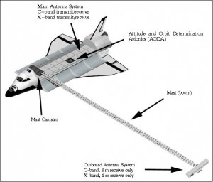
NASA Space Shuttle: The Shuttle Radar Topography Mission (SRTM) used the Space-borne Imaging Radar (SIR-C) and X-Band Synthetic Aperture Radar (X-SAR) to map 140 mile (225 kilometer) wide swaths, imaging most of Earth’s land surface between 60 degrees north and 56 degrees south latitude. Radar antennae were mounted in the Space Shuttle’s cargo bay, and at the end of a deployable 60 meter mast that formed a long-baseline interferometer. The interferometric SAR data was used to generate very accurate 3-D surface profile maps of the terrain.

Shuttle STRMSource: NASA / Jet Propulsion Laboratory

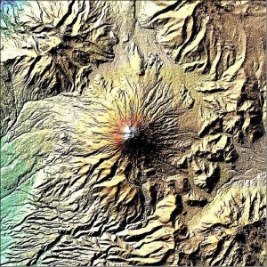
An example of SRTM image quality is shown in the following X-SAR false-color digital elevation map of Mt. Cotopaxi in Ecuador.

Shuttle STRM imageSource: NASA / Jet Propulsion Laboratory

You can find more information on SRTM at the following link:

https://directory.eoportal.org/web/eoportal/satellite-missions/s/srtm

ESA’s Sentinel satellites: Refer to my 4 May 2015 post, “What Satellite Data Tell Us About the Earthquake in Nepal,” for information on how the European Space Agency (ESA) assisted earthquake response by rapidly generating a post-earthquake 3-D ground displacement map of Nepal using SAR data from multiple orbits (i.e., pre- and post-earthquake) of the Sentinel-1A satellite.  You can find more information on the ESA Sentinel SAR platform at the following link:

http://www.esa.int/Our_Activities/Observing_the_Earth/Copernicus/Sentinel-1/Introducing_Sentinel-1

You will find more general information on space-based SAR remote sensing applications, including many high-resolution images, in a 2013 European Space Agency (ESA) presentation, “Synthetic Aperture Radar (SAR): Principles and Applications”, by Alberto Moreira, at the following link:

https://earth.esa.int/documents/10174/642943/6-LTC2013-SAR-Moreira.pdf

ISAR Basics

ISAR technology uses the relative movement of the target rather than the emitter to create the synthetic aperture. The ISAR antenna can be mounted in a airborne platform. Alternatively, ISAR also can be used by one or more ground-based antennae to generate a 2-D or 3-D radar image of an object moving within the field of view.

ISAR Applications

Maritime surveillance: Maritime surveillance aircraft commonly use ISAR systems to detect, image and classify surface ships and other objects in all weather conditions. Because of different radar reflection characteristics of the sea, the hull, superstructure, and masts as the vessel moves on the surface of the sea, vessels usually stand out in ISAR images. There can be enough radar information derived from ship motion, including pitching and rolling, to allow the ISAR operator to manually or automatically determine the type of vessel being observed. The U.S. Navy’s new P-8 Poseidon patrol aircraft carry the AN/APY-10 multi-mode radar system that includes both SAR and ISAR modes of operation.

The principles behind ship classification is described in detail in the 1993 MIT paper, “An Automatic Ship Classification System for ISAR Imagery,” by M. Menon, E. Boudreau and P. Kolodzy, which you can download at the following link:

https://www.ll.mit.edu/publications/journal/pdf/vol06_no2/6.2.4.shipclassification.pdf

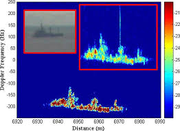
You can see in the following example ISAR image of a vessel at sea that vessel classification may not be obvious to the casual observer. I can see that an automated vessel classification system is very useful.

Ship ISAR image

Source: Blanco-del-Campo, A. et al., http://ieeexplore.ieee.org/xpl/login.jsp?tp=&arnumber=5595482&url=http%3A%2F%2Fieeexplore.ieee.org%2Fiel5%2F7361%2F5638351%2F05595482.pdf%3Farnumber%3D5595482

Imaging Objects in Space: Another ISAR (also called “delayed Doppler”) application is the use of one or more large radio telescopes to generate radar images of objects in space at very long ranges. The process for accomplishing this was described in a 1960 MIT Lincoln Laboratory paper, “Signal Processing for Radar Astronomy,” by R. Price and P.E. Green.

Currently, there are two powerful ground-based radars in the world capable of investigating solar system objects: the National Aeronautics and Space Administration (NASA) Goldstone Solar System Radar (GSSR) in California and the National Science Foundation (NSF) Arecibo Observatory in Puerto Rico. News releases on China’s new FAST radio telescope have not revealed if it also will be able to operate as a planetary radar (see my 18 February 2016 post).

The 230 foot (70 meter) GSSR has an 8.6 GHz (X-band) radar transmitter powered by two 250 kW klystrons. You can find details on GSSR and the techniques used for imaging space objects in the article, “Goldstone Solar System Radar Observatory: Earth-Based Planetary Mission Support and Unique Science Results,” which you can download at the following link:

http://echo.jpl.nasa.gov/asteroids/Slade_Benner_Silva_IEEE_Proceedings.pdf

The 1,000 foot (305 meter) Arecibo Observatory has a 2.38 GHz (S-band) radar transmitter, originally rated at 420 kW when it was installed in 1974, and upgraded in 1997 to 1 MW along with other significant upgrades to improve radio telescope and planetary radar performance. You will find details on the design and upgrades of Arecibo at the following link:

http://www.astro.wisc.edu/~sstanimi/Students/daltschuler_2.pdf

The following examples demonstrate the capabilities of Arecibo Observatory to image small bodies in the solar system.

  • In 1999, this radar imaged the Near-Earth Asteroid 1999 JM 8 at a distance of about 5.6 million miles (9 million km) from Earth. The ISAR images of this 1.9 mile 3-km) sized object had a resolution of about 49 feet (15 meters).
  • In November 1999, Arecibo Observatory imaged the tumbling Main-Belt Asteroid 216 Kleopatra. The resulting ISAR images, which made the cover of Science magazine, showed a dumbbell-shaped object with an approximate length of 134.8 miles (217 kilometers) and varying diameters up to 58.4 miles (94 kilometers).

Asteroid image  Source: Science

More details on the use of Arecibo Observatory to image planets and other bodies in the solar system can be found at the following link:

http://www.naic.edu/general/index.php?option=com_content&view=article&id=139&Itemid=474

The NASA / Jet Propulsion Laboratory Asteroid Radar Research website also contains information on the use of radar to map asteroids and includes many examples of asteroid radar images. Access this website at the following link:

http://echo.jpl.nasa.gov

Miniaturization

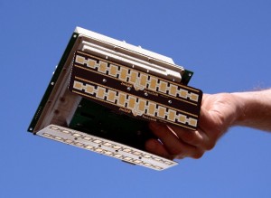
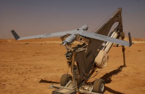
In recent years, SAR units have become smaller and more capable as hardware is miniaturized and better integrated. For example, Utah-based Barnard Microsystems offers a miniature SAR for use in lightweight UAVs such as the Boeing ScanEagle. The firm claimed that their two-pound “NanoSAR” radar, shown below, weighed one-tenth as much as the smallest standard SAR (typically 30 – 200 pounds; 13.6 – 90.7 kg) at the time it was announced in March 2008. Because of power limits dictated by the radar circuit boards and power supply limitations on small UAVs, the NanoSAR has a relatively short range and is intended for tactical use on UAVs flying at a typical ScanEagle UAV operational altitude of about 16,000 feet.

Barnard NanoSARSource: Barnard Microsystems

ScanEagle_UAVScanEagle UAV. Source: U.S. Marine Corps.

Nanyang Technological University, Singapore (NTU Singapore) recently announced that its scientists had developed a miniaturized SAR on a chip, which will allow SAR systems to be made a hundred times smaller than current ones.

?????????????????????????????????????????????????????????Source: NTU

NTU reports:

“The single-chip SAR transmitter/receiver is less than 10 sq. mm (0.015 sq. in.) in size, uses less than 200 milliwatts of electrical power and has a resolution of 20 cm (8 in.) or better. When packaged into a 3 X 4 X 5-cm (0.9 X 1.2 X 1.5 in.) module, the system weighs less than 100 grams (3.5 oz.), making it suitable for use in micro-UAVs and small satellites.”

NTU estimates that it will be 3 to 6 years before the chip is ready for commercial use. You can read the 29 February 2016 press release from NTU at the following link:

http://media.ntu.edu.sg/NewsReleases/Pages/newsdetail.aspx?news=c7aa67e7-c5ab-43ae-bbb3-b9105a0cd880

With such a small and hopefully low cost SAR that can be integrated with low-cost UAVs, I’m sure we’ll soon see many new and useful radar imaging applications.

Remarkable Multispectral View of Our Milky Way Galaxy

Peter Lobner, updated 18 August 2023

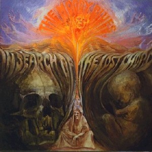
Moody Blues cover - In search of the lost chordAlbum Album cover art credit: Deram Records

Some of you may recall the following lyrics from the 1968 Moody Blues song, “The Word,” by Graeme, Edge, from the album “In Search of the Lost Chord”:

This garden universe vibrates complete

Some, we get a sound so sweet

 Vibrations reach on up to become light

And then through gamma, out of sight

Between the eyes and ears there lie

The sounds of color and the light of a sigh

And to hear the sun, what a thing to believe

But it’s all around if we could but perceive

 To know ultraviolet, infrared and X-rays

Beauty to find in so many ways

On 24 February 2016, the European Southern Observatory (ESO) Consortium announced that it has completed the ATLASGAL Survey of the Milky Way. The survey mapped the entire galactic plane visible from the southern hemisphere at sub-millimeter wavelengths, between infrared light and radio waves, using the Atacama Pathfinder EXperiment (APEX) telescope located at 5,100 meters (16,732 ft.) above sea level in Chile’s Atacama region. The southern sky is particularly important because it includes the galactic center of our Milky Way. The Milky Way in the northern sky has already been mapped by the James Clerk Maxwell Telescope, which is a sub-millimeter wavelength telescope at the Mauna Kea Observatory in Hawaii.

The new ATLASGAL maps cover an area of sky 140 degrees long and 3 degrees wide. ESO stated that these are the sharpest maps yet made, and they complement those from other land-based and space-based observatories. The principal space-based observatories are the following:

  • European Space Agency’s (ESA) Plank satellite: Mission on-going, mapping anisotropies of the cosmic microwave background at microwave and infrared frequencies.
  • ESA’s Herschel Space Observatory: Mission on-going, conducting sky surveys in the far-infrared and sub-millimeter frequencies.
  • National Aeronautics and Space Administration (NASA) Spitzer Space Telescope: Mission on-going, conducting infrared observations and mapping as described in my 1 April 2015 post.
  • NASA’s Hubble Space Telescope: Mission on-going, observing and mapping at ultraviolet, optical, and infrared frequencies.
  • NASA’s Chandra X-Ray Observatory: Mission on-going, observing and mapping X-ray sources.
  • NASA’s Compton Gamma Ray Observatory: Mission ended in 2000. Observed and mapped gamma ray and x-ray sources.

ESO reported that the combination of Planck and APEX data allowed astronomers to detect emission spread over a larger area of sky and to estimate from it the fraction of dense gas in the inner galaxy. The ATLASGAL data were also used to create a complete census of cold and massive clouds where new generations of stars are forming.

You can read the ESO press release at the following link:

https://www.eso.org/public/news/eso1606/

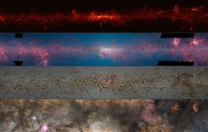
Below is a composite ESO photograph that shows the same central region of the Milky Way observed at different wavelengths.

ESO Multispectral view of Milky WaySource: ESO/ATLASGAL consortium/NASA/GLIMPSE consortium/VVV Survey/ESA/Planck/D. Minniti/S. Guisard. Acknowledgement: Ignacio Toledo, Martin Kornmesser

  • The top panel shows compact sources of sub-millimeter radiation detected by APEX as part of the ATLASGAL survey, combined with complementary data from ESA’s Planck satellite, to capture more extended features.
  • The second panel shows the same region as seen in shorter, infrared wavelengths by the NASA Spitzer Space Telescope
  • The third panel shows the same part of sky again at even shorter wavelengths, the near-infrared, as seen by ESO’s VISTA infrared survey telescope at the Paranal Observatory in Chile. Regions appearing as dark dust tendrils in the third panel show up brightly in the ATLASGAL view (top panel).
  • The bottom panel shows the more familiar view in visible light, where most of the more distant structures are hidden from view

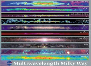
NASA’s Goddard Space Flight Center also  created a multispectral view of the Milky Way, which  is shown in the following composite photograph of the same central region of the Milky Way observed at different wavelengths.

NASA Goddard multispectralSource: NASA Goddard Space Flight Center

Starting from the top, the ten panels in the NASA image cover the following wavelengths.

  • Radio frequency (408 MHz)
  • Atomic hydrogen
  • Radio frequency (2.5 GHz)
  • Molecular hydrogen
  • Infrared
  • Mid-infrared
  • Near-infrared
  • Optical
  • X-ray
  • Gamma ray

The Moody Blues song, “The Word,” ends with the following lyrics:

 Two notes of the chord, that’s our full scope

But to reach the chord is our life’s hope

And to name the chord is important to some

So they give it a word, and the word is “Om”

While “Om” (pronounced or hummed “ahh-ummmm”) traditionally is a sacred mantra of Hindu, Jain and Buddhist religions, it also may be the mantra of astronomers as they unravel new secrets of the Milky Way and, more broadly, the Universe. I suspect that completing the ATLASGAL Survey of the Milky Way was an “Om” moment for the many participants in the ESO Consortium effort.

For more information

China’s Five Hundred Meter Aperture Spherical Telescope (FAST) will be the World’s Largest Radio Telescope

Peter Lobner

Updated 20 October 2019

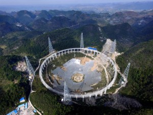
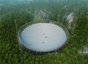
FAST is being built in a remote region of China, in the southwestern province of Guizhou. Completion is planned for September 2016, at which time FAST will replace the similar 305 meter (1,000 ft) Arecibo Observatory in Puerto Rico as the world’s largest radio telescope.

China builds World's Largest Radio Telescope

FAST pic 2Source: FAST

Main features of FAST are:

  • The telescope is built in a natural karst depression
  • The 500 meter (1,640 ft) active main reflector is comprised of 4,600 triangular panels
    • directly corrects for spherical aberration
    • allows the telescope to be steered to view the sky within 40 degrees from zenith
  • The focus cabin suspended above the main reflector houses nine feeds for receivers covering a frequency range of 70MHz – 3 GHz
  • In comparison to Arecibo, FAST is expected to have the following performance parameters:
    • 2 times greater sensitivity
    • 5 – 10 times faster surveying speed
    • 2 – 3 times greater sky coverage due to the steering capability of the active main reflector

Observation programs are expected to include the following:

  • Large scale neutral hydrogen survey
    • Will support studies such as dark matter and dark galaxies, large scale structures and dark energy, and galaxy formation and evolution
  • Detect interstellar molecules
    • The receiver bands of FAST are designed to cover OH (hydroxyl radical), CH3OH (methanol) and 12 other molecular lines
  • Survey the transient sky, including pulsar observations
  • Operate as part of the international very long baseline interferometry (VLBI) network

All residents within 3 miles of the new telescope (more than 9,000 people) are being relocated to create an electromagnetic “quiet zone” around the telescope.

You can download a fact sheet on the telescope at the following link:

http://www.cospa.ntu.edu.tw/aappsbulletin/data/19-2/33FAST.pdf

You can download a more detailed paper entitled, “The Five Hundred Meter Aperture Spherical Telescope (FAST) Project,” which provides details on the telescope design, at the following link:

http://arxiv.org/pdf/1105.3794.pdf

An English language version of the FAST project website appears not to have been maintained since 2010, but can be accessed at the following link:

http://fast.bao.ac.cn/en/FAST.html

 5 July 2016 Update:  FAST construction complete

The Chinese government announced completion of FAST on 4 July 2016.  The project took roughly five years to complete and cost about $180 million.

 22 October 2019 Update:  FAST is operational

FAST Chief Engineer, JIANG Peng, announced that FAST has been open to Chinese astronomers since April 2019. After the National Construction Acceptance in September 2019, it is expected that FAST will be available for use by astronomers from other nations.   You can read more here:

https://www.universetoday.com/143346/chinas-fast-telescope-the-worlds-largest-single-radio-dish-telescope-is-now-fully-operational/

and here:

https://www.nature.com/articles/d41586-019-02790-3

NSF and LIGO Team Announce First Detection of Gravitational Waves

Peter Lobner

Today, 11 February 2016, the National Science Foundation (NSF) and the Laser Interferometer Gravitational-Wave Observatory (LIGO) project team announced that the first detection of gravitational waves occurred on 14 September 2015. You can view a video of this announcement at the following link:

https://www.youtube.com/watch?v=_582rU6neLc

The first paper on this milestone event, “Observation of Gravitational Waves From a Binary Black Hole Merger,” is reported in Physical Review Letters, at the following link:

http://journals.aps.org/prl/pdf/10.1103/PhysRevLett.116.061102

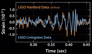
The recorded signals from the two LIGO sites, Livingston, LA and Hanford, WA, are shown below, with the Hanford data time shifted to account for the slightly later arrival time of the gravitational wave signal at that detector location. The magnitude of the gravitational wave signal was characterized as being just below the detection threshold of LIGO before installation of the new advanced detectors, which improve LIGO sensitivity by a factor of 3 to 10.

LIGO signals

Source: NSF/LIGO

This milestone occurred during the engineering testing phase of the advanced LIGO detectors, before the start of their first official “observing run” on 18 September 2015.

Analysis and simulations conducted on the data indicate that the observed gravitational wave signals were generated when two orbiting black holes coalesced into a single black hole of smaller total mass and ejected about three solar masses of energy as gravitational waves.

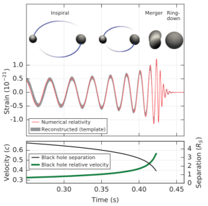
In the Physical Review Letters paper, the authors provide the following diagram, which gives a physical interpretation of the observed gravitational wave signals.

Binary black holes merge

Note the very short timescale of this extraordinarily dynamic process. The recorded gravitational wave signals yielded an audible “chirp” when the two black holes merged.

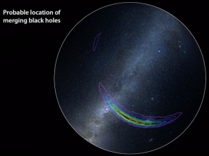
With only two LIGO detectors, the source of the observed gravitational waves could not be localized, but the LIGO team reported that the source was in the southern sky, most likely in the vicinity of the Magellanic Clouds.

Localization of black hole merger Source: NSF/LIGO

The ability to localize gravitational wave signals will improve when additional gravitational wave detectors become operational later in this decade.

For more information on the current status of LIGO and other new-generation gravitational wave detectors, see my 16 December 2015 post: “100th Anniversary of Einstein’s Theory of General Relativity and the Advent of a New Generation of Gravity Wave Detectors.”

Update: 3 October 2017

 Congratulations to Rainer Weiss, Barry C. Barish, and Kip S. Thorne, all members of the LIGO / VIRGO Collaboration, for their award of the 2017 Nobel Prize in Physics for the first direct observation of gravitational waves. You can read the press release from the Royal Swedish Academy of Sciences here:

https://www.nobelprize.org/nobel_prizes/physics/laureates/2017/press.html

You also can read the scientific background on this award on the Royal Swedish Academy of Sciences website at the following link:

https://www.nobelprize.org/nobel_prizes/physics/laureates/2017/advanced-physicsprize2017.pdf