Modern Airships

This August 2016 post, which included links to 14 articles on specific historic and modern  airships, was replaced in August 2019.

“Modern Airships” now is a three-part post that contains an overview of modern airship technology in Part 1 and links in Parts 1, 2 and 3 to more than 275 individual articles on historic and advanced airship designs. Here are the links to all three parts:

I hope you’ll find the expanded Modern Airships series of posts to be informative, useful, and different from any other single source of information on this subject.

Best regards,

Peter Lobner

August 2019

The First Digital Camera Started a Revolution in Photography and Much More

Peter Lobner

In 1975, I was shooting photographs with a Nikon F2 single lens reflex (SLR) film camera I bought two years before. The F2 was introduced by Nikon in September 1971, and was still Nikon’s top-of-the-line SLR when I bought it in 1973. I shot slide film because I liked the quality of the large projected images. I was quite happy with my Kodak Carousel slide projector and circular slide trays, even though the trays took up a lot of storage space. Getting print copies of slides for family and friends took time and money, but I was used to that. Little did I suspect, at the time, that a revolution was brewing at Eastman Kodak.

The first digital camera prototype: 1975

In 1975, Steve Sasson invented the digital camera while working at Kodak. This first digital camera weighed 8 pounds (3.6kg), was capable of taking 0.01 megapixel (10,000 pixel) black & white photos, and storing 30 photos on a removable digital magnetic tape cassette. An image captured by the camera’s 100 x 100 pixel Fairchild CCD (charge coupled device) sensor was stored in RAM (random access memory) in about 50 milliseconds (ms). Then it took 23 seconds to record one image to the digital cassette tape. For the first time, photos were captured on portable digital media, which made it easy to rapidly move the image files into other digital systems.

Sasson holding first digital cameraSteve Sasson & the first digital camera. Source: MagaPixel

David Friedman, who has interviewed many contemporary inventors, interviewed Steve Sasson in 2011. I think you’ll enjoy his short video interview, which reveals details of how the first digital camera was designed and built, at the following link:

https://vimeo.com/22180298

Arrival of consumer digital cameras: 1994

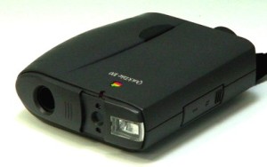
In February 1994, almost 20 years after Steve Sasson’s first digital camera, Apple introduced the Kodak-manufactured QuickTake 100, which was the first mass market color consumer digital camera available for under $1,000.

Apple Quicktake 100   Apple QuickTake 100. Source: Apple

 The QuickTake 100 could take digital photos at either 0.3 megapixels (high-resolution) or 0.08 megapixels (standard-resolution), and store the image files on a internal (not removable) 1MB flash EPROM (erasable programmable read-only memory). The EPROM could store 32 standard or eight high-resolution images, or a combination. Once downloaded, these modest-resolution images were adequate for many applications requiring small images, such as pasting a photo into an electronic document.

In the following years before the millennium, the consumer and professional photography markets were flooded with a vast array of rapidly improving digital cameras and much lower prices for entry-level models. While my old Nikon F2 film camera remained a top-of-the-line camera for many years back in the 1970s, many newly introduced digital cameras were obsolete by the time they were available in the marketplace.

For a comprehensive overview of the evolution of digital photography, I refer you to Roger L. Carter’s DigiCamHistory website, which contains an extensive history of film and digital photography from the 1880s thru 1999.

http://www.digicamhistory.com/Index.html

Film cameras are dead – well almost. On 22 June 2009, Kodak announced that it would cease selling Kodachrome film by the end of 2009. Except for continuing production of professional film for movies, Kodak exited the film business after 74 years. FujiFilm and several other manufacturers continue to offer a range of print and slide film. You can read an assessment of the current state of the film photography industry at the following link:

http://www.thephoblographer.com/2015/04/23/manufacturers-talk-state-film-photography-industry/#.V73QqWWVtbc

Arrival of camera phones: 2000

In the new millennium, we were introduced to a novel new type of camera, the camera phone, which was first introduced in Japan in 2000. There seems to be some disagreement as to which was the first camera phone. The leading contenders are:

  • Samsung SCH-V200, which could take 0.35 megapixel photos and store them on an internal memory device
  • Sharp (J-Phone) J-SH04, which could take 0.11 megapixel photos and send them electronically

At that time, small point-and-shoot digital cameras typically were taking much better photos in the 0.78 – 1.92 megapixel range (1024 x 768 pixels to 1600 x 1200 pixels), with high-end digital SLRs taking 10 megapixel photos (3888 x 2592 pixels).

In November 2002, Sprint became the first service provider in the U.S. to offer a camera phone, the Sanyo SCP-5300, which could take 0.3 megapixel (640 x 480 pixels) photos and included many features found on dedicated digital cameras.

Sanyo SCP-5300

Sanyo SCP-5300. Source: Sprint

In late 2003, the Ericsson Z1010 mobile phone introduced the front-facing camera, which enabled the user to conveniently take a “selfie” photo or video while previewing the image on the phone’s video display. Narcissists around the world rejoiced! A decade later they rejoiced again following the invention of the now ubiquitous, and annoying “selfie stick”.

Ericsson Z1010

Ericsson Z1010. Source: www.GSMArena.com

You’ll find more details on the history of the camera phone at the following link:

http://www.digitaltrends.com/mobile/camera-phone-history/

Arrival of smartphones:

The 1993 IBM Simon is generally considered to be the first “smart phone.” It could function as a phone, pager, and PDA (personal desktop assistant) , with simple applications for calendar, calculator, and address book, but no built-in camera. The important feature of the smart phone was its ability to run various applications to expand its functionality.

The first mobile phone actually referred to as a “smartphone” was Erikkson’s 1997 model GS88 concept phone, which led in 2000 to the Erikkson model R380. This was the first mobile phone marketed as a smartphone…..but it had no camera.

With the introduction of camera phones and smartphones in 2000, and front-facing cameras in 2003, it wasn’t long before the most popular mobile phones were smartphones with two cameras. Now, just 13 years after this convergence of technology, it seems that smartphones are everywhere and these devices have evolved into very capable tools for high-resolution still and video photography as well as photo processing and video editing using specialized applications that can be installed by the user.

With these capabilities available in a small, integrated mobile device, it’s no wonder that the sale of dedicated digital cameras has been declining rapidly.

Impact of mobile phone cameras on dedicated camera sales

Here is a comparison of the digital image sensors on three representative modern cameras:

  • Nikon D800 DSLR camera: 36 megapixels (7360 × 4912 pixels), FX full-frame (35.9 x 24.0 mm, 43.18 mm diagonal) CMOS image sensor
  • Sony DSC-HX90V compact point-and-shoot camera: 18.2 megapixels (4896 x 3672 pixels), 1/2.3 type (6.17mm x 4.55mm, 7.67 mm diagonal) CMOS image sensor
  • Apple iPhone 6 cameras: Main camera: 8 megapixels (3264 x 2448 pixels), 1/2.94 type (4.8mm x 3.6mm, 6.12 mm diagonal) CMOS, Sony Exmor RS image sensor. Front-facing camera: 1.2 megapixels

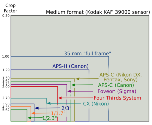
The Nikon’s FX sensor is as big as a the photo’s image would be in a 35 mm film camera. This is called a “full frame” sensor. Most digital cameras have smaller image sensors, as shown in the following comparison chart.

Comparison of digital image sensor sizesSource: www.techhive.com

The IPhone 6 image sensor is smaller than any shown in the above chart. Nonetheless, its photo and video quality can be quite good.

For more information on digital camera image sensors, check out the 2013 article by Jackie Dove, “Demystifying digital camera sensors once and for all,” at the following link:

http://www.techhive.com/article/2052159/demystifying-digital-camera-sensors-once-and-for-all.html

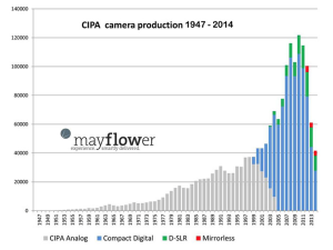
The rapid rise in the quality of mobile phone cameras is making small digital cameras redundant, and is having a dramatic impact on the sale of dedicated cameras, as shown in the following chart.

Screen Shot 2016-08-24 at 1.24.20 PM

Source: Mayflower Concepts, petapixel.com

The above chart indicates that only 40,000 dedicated cameras of all types were sold in 2014; far below the peak of about 120,000 units in 2010. The biggest impact has been on compact digital cameras, with the DSLR cameras holding their own, at least for the moment.

While I still like my current Nikon DSLR, I have to admit that I’ve found some higher-end compact digital cameras that have most of the capabilities I want in an SLR but in a much smaller package. While I won’t make my mobile phone camera my primary camera, I may retire the DSLR.

Immediate communications and privacy

The rapid rise of the smartphone was enabled by the deployment of 3G and 4G cellular phone service. See my 20 March 2016 post on the evolution of cellular service for details on the deployment timeline.

With access to capable wireless communications networks and a host of photo and video applications and services, the cameras on mobile phones became tools for capturing images or videos of anything and instantly communicating these via the Internet to audiences that can span the globe. We’re now living in a world where many awkward moments get recorded, meals get photographed before they’re eaten, and there’s a need to post a selfie during an event to prove that you actually were there (and of course, to impress your friends). Thanks to the advent of the cloud, all of these digital photographic memories can be preserved online forever, or at least until you don’t want to continue paying for cloud storage.

Privacy is becoming a thing of the past. What happens in Vegas probably gets photographed by someone and, if you’re lucky, stays in the cloud…..until it’s needed, or hacked.

I don’t think Steve Sasson imagined such a future when he invented the first digital camera in 1975.

Exploring Microgravity Worlds

Peter Lobner

1.  Background:

We’re all familiar with scenes of the Apollo astronauts bounding across the lunar surface in the low gravity on the Moon, where gravity (g) is 0.17 of the gravity on the Earth’s surface. Driving the Apollo lunar rover kicked up some dust, but otherwise proved to be a practical means of transportation on the Moon’s surface. While the Moon’s gravity is low relative to Earth, techniques for achieving lunar orbit have been demonstrated by many spacecraft, many soft landings have been made, locomotion on the Moon’s surface with wheeled vehicles has worked well, and there is no risk of flying off into space by accidentally exceeding the Moon’s escape velocity.

There are many small bodies in the Solar System (i.e., dwarf planets, asteroids, comets) where gravity is so low that it creates unique problems for visiting spacecraft and future astronauts: For example:

  • Spacecraft require efficient propulsion systems and precise navigation along complex trajectories to rendezvous with the small body and then move into a station-keeping position or establish a stable orbit around the body.
  • Landers require precise navigation to avoid hazards on the surface of the body (i.e., craters, boulders, steep slopes), land gently in a specific safe area, and not rebound back into space after touching down.
  • Rovers require a locomotion system that is adapted to the specific terrain and microgravity conditions of the body and allows the rover vehicle to move across the surface of the body without risk of being launched back into space by reaction forces.
  • Many asteroids and comets are irregularly shaped bodies, so the surface gravity vector will vary significantly depending on where you are relative to the center of mass of the body.

You will find a long list of known objects in the Solar System, including many with diameters less than 1 km (0.62 mile), at the following link:

https://en.wikipedia.org/wiki/List_of_Solar_System_objects_by_size

You can determine the gravity on the surface of a body in the Solar System using the following equation:

Equation for g

where (using metric):

g = acceleration due to gravity on the surface of the body (m/sec2)

G = universal gravitational constant = 6.672 x 10⁻¹¹ m3/kg/sec2

M = mass of the body (kg)

r = radius of the body (which is assumed to be spherical) (m)

You can determine the escape velocity from a body using the following equation:

Equation - Escape velocity

Applying these equations to the Earth and several smaller bodies in in the Solar System yields the following results:
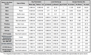
g and escape velocity table

Note how weak the gravity is on the small bodies in this table. These are very different conditions than on the surface of the Moon or Mars where the low gravity still allows relatively conventional locomotion.

As noted in my 31 December 2015 post, the “U.S. Commercial Space Launch Competitiveness Act,” which was signed into law on 25 November 2015, opens the way for U.S. commercial exploitation of space, including commercial missions to asteroids and comets.  Let’s take a look at missions to these microgravity worlds and some of the unique issues associated with visiting a microgravity world.

2.  Recent and Current Missions to Asteroids and Comets

There have been several spacecraft that have made a successful rendezvous with one or more small bodies in the Solar System. Several have been fly-by missions. Four spacecraft have flown in close formation with or entered orbit around low-gravity bodies. Three of these missions included landing on (or at least touching) the body, and one returned very small samples to Earth. These missions are:

  • National Aeronautics and Space Administration’s (NASA) NEAR-Shoemaker
  • Japan Aerospace Exploration Agency’s (JAXA) Hayabusa
  • European Space Agency’s (ESA) Rosetta
  • NASA’s Dawn

In addition, China’s Chang’e 2 mission demonstrated its ability to navigate to an asteroid intercept after completing its primary mission in lunar orbit. JAXA’s Hayabusa 2 mission currently is enroute to asteroid rendezvous.

Following is a short synopsis of each of these missions.

NASA’s NEAR-Shoemaker Mission (1996 – 2001): This mission was launched 17 February 1996 and on 27 June 1997 flew by the asteroid 253 Mathilde at a distance of about 1,200 km (746 miles).   On 14 February 2000, the spacecraft reached its destination and entered a near-circular orbit around the asteroid 433 Eros, which is about the size of Manhattan. After completing its survey of Eros, the NEAR spacecraft was maneuvered close to the surface and it touched down on 12 February 2001, after a four-hour descent, during which it transmitted 69 close-up images of the surface. Transmissions continued for a short time after landing. NEAR-Shoemaker was the first man-made object to soft-land on an asteroid.
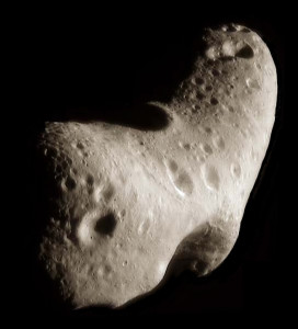
Asteroid Eros                Asteroid EROS. Source: NASA/JPL/JHUAPL

JAXA’s Hayabusa Mission (2003 – 2010): The Hayabusa spacecraft was launched in May 2003. This solar-powered, ion-driven spacecraft rendezvoused with near-Earth asteroid 25143 Itokawa in mid-September 2005.
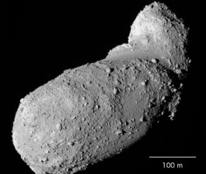
Asteroid Itokawa           Asteroid Itokawa. Source: JAXA

Hayabusa carried the solar-powered MINERVA (Micro/Nano Experimental Robot Vehicle for Asteroid) mini-lander, which was designed to be released close to the asteroid, land softly, and move across the surface using an internal flywheel and braking system to generate the momentum needed to hop in microgravity. However, MINERVA was not captured by the asteroid’s gravity after being released and was lost in deep space.

In November 2005, Hayabusa moved in from its station-keeping position and briefly touched the asteroid to collect surface samples in the form of tiny grains of asteroid material.
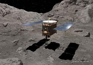
Hayabusa taking a sampleHayabusa in position to obtain samples. Source: JAXA

The spacecraft then backed off and navigated back to Earth using its failing ion thrusters. Hayabusa returned to Earth on 13 June 2010 and the sample-return capsule, with about 1,500 grains of asteroid material, was recovered after landing in the Woomera Test Range in the western Australian desert.

You’ll find a JAXA mission summary briefing at the following link:

https://www.nasa.gov/pdf/474206main_Kuninaka_HayabusaStatus_ExploreNOW.pdf

ESA’s Rosetta Mission (2004 – present): The Rosetta spacecraft was launched in March 2004 and in August 2014 rendezvoused with and achieved orbit around irregularly shaped comet 67P/Churyumov-Gerasimenko. This comet orbits the Sun outside of Earth’s orbit, between 1.24 and 5.68 AU (astronomical units; 1 AU = average distance from Earth’s orbit to the Sun). The size of 67P/Churyumov-Gerasimenko is compared to downtown Los Angeles in the following figure.
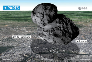
ESA Attempts To Land Probe On CometSource: ESA

Currently, Rosetta remains in orbit around this comet. The lander, Philae, is on the surface after a dramatic rebounding landing on 12 November 2014. Anchoring devices failed to secure Philae after its initial touchdown. The lander bounced twice and finally came to rest in an unfavorable position after contacting the surface a third time, about two hours after the initial touchdown. Philae was the first vehicle to land on a comet and it briefly transmitted data back from the surface of the comet in November 2014 and again in June – July 2015.

NASA’s Dawn Mission (2007 – present): Dawn was launched on 27 September 2007 and used its ion engine to fly a complex flight path to a 2009 gravitational assist flyby of Mars and then a rendezvous with the large asteroid Vesta (2011 – 2012) in the main asteroid belt.
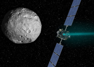
NASA_Dawn_spacecraft_near_Ceres   Dawn approaches Vesta. Source: NASA / JPL Caltech

Dawn spent 14 months in orbit surveying Vesta before departing to its next destination, the dwarf planet Ceres, which also is in the main asteroid belt. On 6 March 2015 Dawn was captured by Ceres’ gravity and entered its initial orbit following the complex trajectory shown in the following diagram.
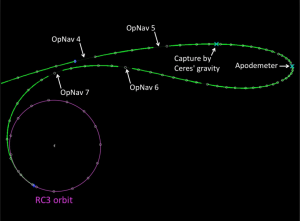
Dawn navigation to Ceres orbit   Dawn captured by Ceres gravity. Source: NASA / JPL Caltech

Dawn is continuing its mapping mission in a circular orbit at an altitude of 385 km (240 miles), circling Ceres every 5.4 hours at an orbital velocity of about 983 kph (611 mph). The Dawn mission does not include a lander.

See my 20 March 2015 and 13 Sep 2015 posts for more information on the Dawn mission.

CNSA’s Chang’e 2 extended mission (2010 – present): The China National Space Agency’s (CNSA) Chang’e 2 spacecraft was launched in October 2010 and placed into a 100 km lunar orbit with the primary objective of mapping the lunar surface. After completing this objective in 2011, Chang’e 2 navigated to the Earth-Sun L2 Lagrange point, which is a million miles from Earth in the opposite direction of the Sun. In April 2012, Chang’e 2 departed L2 for an extended mission to asteroid 4179 Toutatis, which it flew by in December 2012.
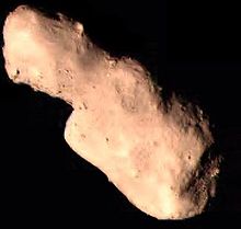
Toutatis_from_Chang'e_2Asteroid Toutatis. Source: CHSA

JAXA’s Hayabusa 2 Mission (2014 – 2020): The JAXA Hayabusa 2 spacecraft was launched on 3 December 2014. This ion-propelled spacecraft is very similar to the first Hayabusa spacecraft. Its planned arrival date at the target asteroid, 1999 JU3 (Ryugu), is in mid-2018.   As you can see in the following diagram, 1999 JU3 is a substantially larger asteroid than Itokawa.
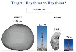
Hayabusa 1-2 target comparisonSource: JAXA

The spacecraft will spend about a year mapping the asteroid using Near Infrared Spectrometer (NIRS3) and Thermal Infrared Imager (TIR) instruments.

Hayabusa 2 includes three solar-powered MINERVA-II mini-landers and one battery-powered MASCOT (Mobile Asteroid Surface Scout) small lander. All landers will be deployed to the asteroid surface from an altitude of about 100 meters (328 feet) so they can be captured by the asteroid’s very weak gravity. The 1.6 – 2.5 kg (3.5 – 5.5 pounds) MINERVA-II landers will deliver imagery and temperature measurements. The 10 kg (22 pound) MASCOT will make measurements of surface composition and properties using a camera, magnetometer, radiometer, and infrared microscope. All landers are expected to make several hops to take measurements at different locations on the asteroid’s surface.
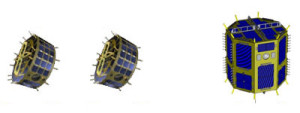
Three MINERVA landers

Three MINERVA mini-landers. Source: JAXA
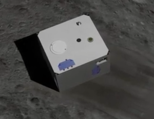
MASCOT lander         MASCOT small lander. Source: JAXA

For sample collection, Hayabusa 2 will descend to the surface to capture samples of the surface material. A device called a Small Carry-on Impactor (SCI) will be deployed and should impact the surface at about 2 km/sec, creating a small crater to expose material beneath the asteroid’s surface. Hayabusa 2 will attempt to gather a sample of the exposed material. More information about SCI is available at the following link:

http://www.lpi.usra.edu/meetings/lpsc2013/pdf/1904.pdf

At the end of 2019, Hayabusa 2 is scheduled to depart asteroid 1999 JU3 (Ryugu) and return to Earth in 2020 with the collected samples. You will find more information on the Hayabusa 2 mission at the JAXA website at the following links:

http://global.jaxa.jp/projects/sat/hayabusa2/

and,

http://www.lpi.usra.edu/sbag/meetings/jan2013/presentations/sbag8_presentations/TUES_0900_Hayabusa-2.pdf

3.  Future Missions:

NASA OSIRIS-REx: This NASA’s mission is expected to launch in September 2016, travel to the near-Earth asteroid 101955 Bennu, map the surface, harvest a sample of surface material, and return the samples to Earth for study. After arriving at Bennu in 2018, the solar-powered OSIRIS-Rex spacecraft will map the asteroid surface from a station-keeping distance of about 5 km (3.1 miles) using two primary mapping instruments: the OVIRS Visible and Infrared Spectrometer and the OTRS Thermal Emission Spectrometer. Together, these instruments are expected to develop a comprehensive map of Bennu’s mineralogical and molecular components and enable mission planners to target the specific site(s) to be sampled. In 2019, a robotic arm on OSIRIS-REx will collect surface samples during one or more very close approaches, without landing. These samples (60 grams minimum) will be loaded into a small capsule that is scheduled to return to Earth in 2023.
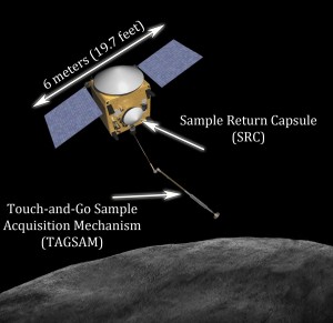
OSIRIS-REx SpacecraftOSIRIS-REx spacecraft. Source: NASA / ASU

For more information on OSIRIS-REx, visit the NASA website at the following link:

http://sservi.nasa.gov/articles/nasas-asteroid-sample-return-mission-moves-into-development/

and the ASU website at the following link:

http://www.asteroidmission.org/objectives/

NASA Asteroid Redirect Mission (ARM): This mission will involve rendezvousing with a near-Earth asteroid, mapping the surface for about a year, and locating a suitable bolder to be captured [maximum diameter about 4 meters (13.1 feet)]. The ARM spacecraft will land and capture the intended bolder, lift off and deliver the bolder into a stable lunar orbit during the first half of the next decade. The current reference target is known as asteroid 2008 EV5.
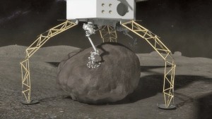
ARM asteroid-capture      ARM lander gripping a bolder on an asteroid. Source: NASA

You can find more information on the NASA Asteroid Redirect Mission at the following links:

https://www.nasa.gov/content/what-is-nasa-s-asteroid-redirect-mission

and

https://www.nasa.gov/pdf/756122main_Asteroid%20Redirect%20Mission%20Reference%20Concept%20Description.pdf

4. Locomotion in Microgravity

OK, you’ve landed on a small asteroid, your spacecraft has anchored itself to the surface and now you want to go out and explore the surface. If this is asteroid 2008 EV5, the local gravity is about 1.79 E-05 that of Earth (less than 2/100,000 the gravity of Earth) and the escape velocity is about 0.6 mph (1 kph). Just how are you going to move about on the surface and not launch yourself on an escape trajectory into deep space?

There is a good article on the problems of locomotion in microgravity in a 7 March 2015 article entitled, “A Lightness of Being,” in the Economist magazine. You can find this article on the Economist website at the following link:

http://www.economist.com/news/technology-quarterly/21645508-space-vehicles-can-operate-ultra-low-gravity-asteroids-and-comets-are

In this article, it is noted that:

“Wheeled and tracked rovers could probably be made to work in gravity as low as a hundredth of that on Earth……But in the far weaker microgravity of small bodies like asteroids and comets, they would fail to get a grip in fine regolith. Wheels also might hover above the ground, spinning hopelessly and using up power. So an entirely different system of locomotion is needed for rovers operating in a microgravity.”

Novel concepts for locomotion in microgravity include:

  • Hoppers / tumblers
  • Structurally compliant rollers
  • Grippers

Hoppers / tumblers: Hoppers are designed to move across a surface using a moving internal mass that can be controlled to transfer momentum to the body of the rover to cause it to tumble or to generate a more dramatic hop, which is a short ballistic trajectory in microgravity. The magnitude of the hop must be controlled so the lander does not exceed escape velocity during a hop. JAXA’s MINERVA-II and MASCOT asteroid landers both are hoppers.

JAXA described the MINERVA-II hopping mechanism as follows:

“MINERVA can hop from one location to another using two DC motors – the first serving as a torquer, rotating an internal mass that leads to a resulting force, sufficient to make the rover hop for several meters. The second motor rotates the table on which the torquer is placed in order to control the direction of the hop. The rover reaches a top speed of 9 centimeters per second, allowing it to hop a considerable distance.”
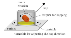
JAXA MINERVA hopperMINERVA torque & turntable. Source: JAXA

The MASCOT hopper operates on a different principle:

“With a mass of not even half a gram in the gravitational field of the asteroid, the (MASCOT) lander can easily withstand its initial contact with the surface and several bounces that are expected upon landing. It also means that only small forces are needed to move the lander from point to point. MASCOT’s Mobility System essentially consists of an off-centered mass installed on an eccentric arm that moves that mass to generate momentum that is sufficient to either rotate the lander to face the surface with its instruments or initiate a hop of up to 70 meters to get to the next sampling site.”
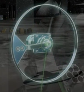
MASCOT Mobility SystemMASCOT mobility mechanism. Source: JAXA

You will find a good animation of MASCOT and its Mobility System at the following link:

http://www.dlr.de/dlr/en/desktopdefault.aspx/tabid-10081/151_read-18664/#/gallery/23722

NASA is examining a class of microgravity rovers called “hedgehogs” that are designed to hop and tumble on microgravity surfaces by spinning and braking a set of three internal flywheels. Cushions or spikes at the corners of the cubic body of a hedgehog protect the body from the terrain and act as feet while hopping and tumbling.
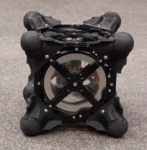
NASA Hedgehog                               NASA Hedgehog prototype. Source: NASA

Read more on the NASA hedgehog rovers at the following link:

http://www.jpl.nasa.gov/news/news.php?feature=4712

Structurally compliant rollers: One means of “rolling” across a microgravity surface is with a deformable structure that allows the location of the center of mass to be controlled in a way that causes the rover to tip over in the desired direction of motion. NASA is exploring the use of a class of rolling rovers called Super Ball Bots, which are terrestrial rovers based on a R. Buckminster Fuller’s tensegrity toy. NASA explains:

“The Super Ball Bot has a sphere-like matrix of cables and joints that could withstand being dropped from a spacecraft high above a planetary surface and hit the ground with a bounce. Once on the planet, the joints could adjust to roll the bot in any direction while housing a data collecting device within its core.”
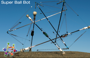
NASA Super Ball Bot                    Source: http://www.nasa.gov/content/super-ball-bot

You’ll find a detailed description of the principles behind tensegrity (tensional integrity) in a 1961 R. Buckminster Fuller paper at the following link:

http://www.rwgrayprojects.com/rbfnotes/fpapers/tensegrity/tenseg01.html

Grippers: Without having a grip on a microgravity body, a rover cannot use sampling tools that generate a reaction force on the rover (i.e., drills, grinders, chippers). For such operations to be successful a rover needs an anchoring system to secure the rover and transfer the reaction loads into the microgravity body.

An approach being developed by Jet Propulsion Laboratory (JPL) involves articulated feet with microspine grippers that have a large number of small claws that can grip irregular rocky surfaces.

JPL microspine gripper           Microspine gripper. Source: NASA / JPL

Such a gripper could be used to hold a rover in place during mechanical sampling activities or to allow a rover to climb across an irregular surface like a spider.  See more about the operation of the NASA / JPL microspine gripper at the following link:

https://www-robotics.jpl.nasa.gov/tasks/taskVideo.cfm?TaskID=206&tdaID=700015&Video=147

5. Conclusions

Missions to small bodies in our Solar System are very complex undertakings that require very advanced technologies in many areas, including: propulsion, navigation, autonomous controls, remote sensing, and locomotion in microgravity. The ambitious current and planned future missions will greatly expand our knowledge of these small bodies and the engineering required to operate spacecraft in their vicinity and on their surface.

While commercial exploitation of dwarf planets, asteroids and comets still may sound like science fiction, the technical foundation for such activities is being developed now. It’s hard to guess how much progress will be made in the next decades. However, I’m convinced that the “U.S. Commercial Space Launch Competitiveness Act,” will encourage commercial investments in space exploration and exploitation and lead to much greater progress than if we depended on NASA alone.

The technologies being developed also may lead, in the long term, to effective techniques for redirecting an asteroid or comet that poses a threat to Earth. Such a development would give our Planetary Defense Officer (see my 21 January 2016 post) an actual tool for defending the planet.
IAEA’s Nuclear Technology Review 2016

Peter Lobner

In June 2016, the International Atomic Energy Agency (IAEA) published a report by the Director General entitled, “Nuclear Technology Review 2016,” which highlights notable developments in 2015 in the following segments of the worldwide nuclear industry.

  • Power applications
    • Generation
    • Fuel cycle
    • Safety
  • Advanced fission
    • Gen III large water cooled reactors
    • Fast reactors
    • Gas-cooled reactors
    • Small & medium size reactors (SMRs)
    • Gen IV advanced reactors
  • Fusion
  • Accelerator and research reactor applications
  • Other applications
    • Emerging industrial applications of radiation technologies
    • Advances in medical imaging technology
    • Use of radiation in connection with managing mosquito disease vectors
    • Use of isotopic techniques for soil management

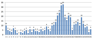
The following chart from the IAEA report shows the age distribution (years of operation) of the worldwide fleet of 441 operating power reactors. The median age of this fleet is about 26 years, and you can see a bow wave of aging nuclear power plants, followed by far fewer younger plants already in operation.

IAEA distribution of reactor age 2015

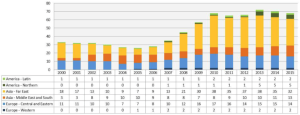
The following chart from the IAEA report shows the number of new plants under construction by region. As of the end of 2015, a total of 68 nuclear power plants were in various stages of their decade-long construction cycles. This chart clearly shows that Western Europe and the Americas are minor players in the construction of new reactors. Most of the new power reactor construction is occurring in Asia and Central / Eastern Europe.

IAEA reactors under construction 2015

IAEA reported that, in 2015, worldwide nuclear power generation reached 381.7 GWe. Projections for the future growth of nuclear power generation thru 2050 were given for two cases:

  • Low case: In this case, new plants just make up for the generating capacity lost from retiring plants. Projected 2050 worldwide generation: 371 GWe.
  • High case: This is a much more optimistic case, yielding about 964 GWe worldwide generation by 2050.

IAEA noted that, “The 21st Conference of the Parties to the United Nations Framework Convention on Climate Change (COP21) resulted in the Paris Agreement that neither identifies nor excludes any particular form of energy.” The Paris Agreement does not discriminate against nuclear power as a means for reaching lower carbon emission goals. In contrast, the U.S. Environmental Protection Agency’s (EPA) euphemistically named “Clean Power Plan” fails to give appropriate credit to nuclear power as a means for utilities and states to reduce the carbon emissions from their portfolio of power plants. (See my 3 July 2015 and 27 November 2015 posts for more on CPP).

IAEA further noted the contribution of nuclear power to meeting lower carbon emission goals:

“Nuclear power has significantly contributed to climate change mitigation by avoiding nearly 2 billion tonnes (metric tons) of carbon dioxide per year. For nuclear power to help limit global warming to 2o C by 2100, its capacity would need to match the high projection to avoid nearly 6.5 billion tonnes of greenhouse gas emissions by 2050.”

Among the small and medium size reactors (SMRs), IAEA noted that the following three were under construction in 2015: Argentina’s CAREM-25, Russia’s KLT-40S, and China’s HTR-PM. Another dozen SMRs were considered to be in the advanced design stage and potentially deployable in the near-term.

IAEA maintains its Advanced Reactors Information System (ARIS), as I reported in my 13 February 2015 post. This is a very comprehensive source of information on all types of advanced reactors. You can directly access ARIS at the following link:

https://aris.iaea.org

The “Nuclear Technology Review 2016” provides a useful overview of worldwide nuclear fuel cycle activities:

  • Worldwide uranium mining in more than 15 countries produced about 57,000 tonnes of Uranium (U) in 2015. Kazakhstan is the leading producer, followed by Canada.
  • Worldwide annual capacity for conversion of U to UF6 was about 60,000 tonnes in 2015, approximately matching annual demand. Canada, China, France, Russia, UK and U.S. operate conversion facilities.
  • Worldwide annual enriched light water reactor (LWR) fuel fabrication capacity is about 13,500 tonnes vs. an annual demand of about 7,000 tonnes. In addition, the fuel fabrication capacity for natural uranium fuel for pressurized heavy water reactors (PHWRs) is about 4,000 tonnes vs. a demand of 3,000 tonnes. Thirteen nations produce LWR fuel, and five produce PHWR fuel.
  • Spent fuel reprocessing is being carried out in 5 nations: China, France, India, Russia and UK; with France and Russia offering reprocessing services to international customers. France and UK have the greatest capacity, reprocessing about 1,000 t HM/year.
  • IAEA reported that, “by the end of 2015, (worldwide) spent fuel in storage amounted to around 266,000 tonnes of heavy metal (t HM) and is accumulating at a rate of around 7,000 t HM/year.
  • Several nations are planning or developing their own geologic disposal facilities for spent nuclear fuel

There’s a lot more information in the IAEA report, including information on fusion, accelerators, research reactors, and industrial and medical applications of nuclear technologies. You can download this IAEA report at the following link:

https://www.iaea.org/About/Policy/GC/GC60/GC60InfDocuments/English/gc60inf-2_en.pdf

A Walk in the Woods With Boston Dynamics’ Atlas Robot

Peter Lobner

The DARPA Robotics Challenge (DRC) Finals held in June 2015 demonstrated the rather limited capabilities for state-of-the-art robots, all of which required teleoperators (remote operators) to augment limited autonomous capabilities aboard the robots. One criticism of that competition was that the original rules got watered down because of the limitations of the robot competitors. Performance of the robots could be characterized as slow and deliberate. None of the robotic competitors that fell over could get up and one was decapitated by the fall. Here’s a video compilation of robots falling during the 2015 DARPA finals:

https://www.youtube.com/watch?v=g0TaYhjpOfo

Team KAIST won the competition with their Hubo robot, which didn’t fall, but wasn’t designed to recover from a fall. Team IHMS Robotics placed second in the competition with their Running Man robot, which was based on the Boston Dynamics Atlas robot. Several other teams also based their entries on the Atlas robot. See my 2 July 2015 post on the DRC Finals.

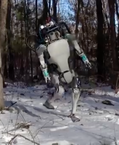
In February 2016, Boston Dynamics posted a video of a new version of their Atlas robot, which they describe as follows:

“A new version of Atlas, designed to operate outdoors and inside buildings. It is specialized for mobile manipulation. It is electrically powered and hydraulically actuated. It uses sensors in its body and legs to balance and LIDAR (Light Imaging, Detection And Ranging) and stereo sensors in its head to avoid obstacles, assess the terrain, help with navigation and manipulate objects. This version of Atlas is about 5′ 9″ tall (about a head shorter than the DRC Atlas) and weighs 180 lbs.”

New version of BD AtlasNew version of Atlas. Source: Boston Dynamics

The autonomous balancing capabilities of this new version, especially its ability to recovery from upsets, seem significantly better than anything seen during the DRC. Atlas recovered nicely from the slip in the above photo. You can see the new version of Atlas perform in the Boston Dynamics video at the following link:

https://www.youtube.com/watch?v=rVlhMGQgDkY

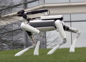
Another interesting new robot from Boston Dynamics is the quadruped SpotMini, which they describe as follows:

“SpotMini is a new smaller version of the Spot robot, weighing 55 lbs. dripping wet (65 lbs. if you include its arm.) SpotMini is all electric (no hydraulics) and runs for about 90 minutes on a charge, depending on what it is doing. SpotMini is one of the quietest robots we have ever built. It has a variety of sensors, including depth cameras, a solid state gyro (IMU, inertial measuring unit) and proprioception sensors in the limbs. These sensors help with navigation and mobile manipulation. SpotMini performs some tasks autonomously, but often uses a human for high-level guidance.”

BD SpotMiniSpotMini. Source: Boston Dynamics

On 23 June 2016, Boston Dynamics posted the following short video of SpotMini in action.

https://www.youtube.com/watch?v=tf7IEVTDjng

Google acquired Boston Dynamics in late 2013. Since then, Google was reorganized, with the “parent firm”, Alphabet, being created in 2015. Shortly thereafter, Google’s research and development group, formerly Google(x), was renamed simply X, or Google X. This group includes a robotics team known as Replicant.

In March 2016, Google announced that Boston Dynamics was up for sale. One reason appears to be that the Boston Dynamics robotics work did not fit in the business model planned for Google X, which has a greater focus on relatively near-term return on investment in the form of a marketable products. You can read an interesting article on Boston Dynamics being put sale at the following link to the Bloomberg Technology website:

http://www.bloomberg.com/news/articles/2016-03-17/google-is-said-to-put-boston-dynamics-robotics-unit-up-for-sale

In late May and early June 2016, several sources (Nikkei, Tech Insider, and engadget) reported that Toyota was negotiating with Alphabet for the sale of Boston Dynamics. Also part of this sale may be Google’s Japanese robotics company, Schaft, which won the 2013 DRC Trials with its S-One humanoid robot. Schaft withdrew from the 2015 DRC Finals for the declared reason of wanting to focus on commercial products. See the article on the engadget website at the following link:

https://www.engadget.com/2016/06/01/toyota-alphabet-boston-dynamics/

It will be interesting to see how and when the sales of Boston Dynamics and Schaft are completed. If these firms do wind up being bought by Toyota, then Toyota’s Research Institute should become a very powerful center for robotic development.

Lunar Lander XCHALLENGE and Lunar XPrize are Paving the way for Commercial Lunar Missions

Peter Lobner

Lunar Lander XCHALLENGE and Lunar XPrize are two competitions promoting the development of technologies, vehicles and systems by private firms for landing unmanned vehicles on the Moon and demonstrating functional capabilities that can support future lunar exploration missions. The legal and regulatory framework for U.S. commercial space activities was greatly simplified in November 2015, when the Commercial Space Launch Competitiveness Act was signed into law. See my 31 December 2015 post for details on this Act.

On 3 August 2016, Lunar XPrize competitor Moon Express became the first private enterprise to be licensed by the U.S. Government (the Federal Aviation Administration) to conduct a mission to the lunar surface. Other Lunar XPrize competitors also are seeking similar approvals in preparation for lunar missions before the end of 2017.

Let’s take a look at how the private sector got this far.

Northrop Grumman / NASA Lunar Lander XCHALLENGE

In October 2007, XPrize and Northrop Grumman, in partnership with NASA’s Centennial Challenges program, launched the $2 million Lunar Lander XCHALLENGE, in which competing teams designed small rocket vehicles capable of routine and safe vertical takeoff and landing for lunar exploration and other applications. You’ll find details on the Lunar Lander XChallenge at the following link and an overview in the following text:

http://lunarlander.xprize.org

Lunar Lander XCHALLENGE badge   Source: XPrize

The XCHALLENGE was divided into two levels.

Level 1:

  • Required a rocket to take off from a designated launch area; climb to a low, fixed altitude of about 50 meters (164 feet); and fly for at least 90 seconds while translating horizontally to a precise landing point on a different landing pad 100 meters (328 feet) from the launch point. The flight must be repeated in reverse within a two and a half hour period.
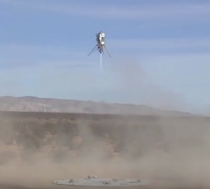
  • Armadillo Aerospace, of Mesquite, TX won the $350K Level 1 first prize in October 2008. Masten Space Systems of Mojave, CA won the $150K Level 1 second place prize on 7 October 2009 when their Xombie rocket completed its flight with an average landing accuracy of 6.3 inches (16 cm).
  • You can watch a short video on the 2008 Level 1 competition and Armadillo Aerospace’s winning Level 1 flight at the following link:

https://www.youtube.com/watch?v=IhnY5tT4YeE

Armadillo Level 1 winner Armadillo Aerospace Level 1 winner. Source: NASA

Level 2:

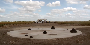
  • Similar to the Level 1 flight profile, but required the rocket to fly for 180 seconds before landing precisely on a simulated lunar surface constructed with craters and boulders 100 meters (328 feet) from the launch point. The minimum flight time was calculated so that the Level 2 mission closely simulated the power needed to perform a real descent from lunar orbit down to the surface of the Moon.

XCHALLENGE lunar landing siteLevel 2 landing site. Source: NASA

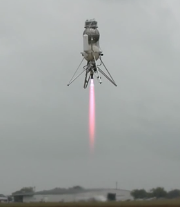
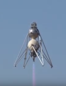
  • Masten Space Systems won the $1M Level 2 first prize with the flight of their Xoie rocket on 30 October 2009. Xoie completed its Level 2 flight with an average landing accuracy of about 7.5 inches (19 cm). Armadillo Aerospace took second place and a $500K prize with the 12 September 2009 flight of their Scorpius (Super-mod) rocket, which had an average landing accuracy of about 34 inches (89 cm). These prizes were awarded on 5 November 2009 in Washington D.C.

Xoie winning Level 2 flightMasten Aerospace Xoie: Level 2 winner. Source: NASA.

  • You can watch a short video summary on the XCHALLENGE results, including the winning flight by Xoie at the following link:

https://www.youtube.com/watch?v=MAvZxa1VXKI

Armadillo Scorpius Level 2Armadillo Aerospace’s Scorpius: Level 2 second place. Source: NASA

  • You can watch a short video on the Scorpius 2009 flight at the following link:

https://www.youtube.com/watch?v=ALKvai4p7OE

The other XCHALLENGE competitors, TrueZer0 and Unreasonable Rockets, failed to qualify for Level 1 or 2.

Google Lunar XPrize

The Google Lunar XPrize was created in 2007, overlapping with the Northrop Grumman / NASA Lunar Lander XCHALLENGE. The Lunar XPrize is intended to actually deliver payloads to the Moon and “incentivize space entrepreneurs to create a new era of affordable access to the Moon and beyond.” The motto for the Google XPrize is: “Back to the Moon for good.”

The basic mission requirements are:

  • Land a privately funded rover on the Moon at a site announced in advance.
  • Travel at least 500 meters along a deliberate path on the lunar surface.
  • Transmit two “Mooncasts” from the surface of the Moon, including specified types of videos and still images.
  • Receive specified data uplinks from Earth and re-transmit the data back to Earth.
  • Deliver a small payload provided by XPrize (not to exceed 500 grams).
  • Private funding for 90% of the total mission cost. No more than 10% government funding, including the value of in-kind support.
  • Launch contract in place by the end of 2016 and mission completion by the end of 2017.

The primary incentives are large financial award to the first and second teams that accomplish all of the mission requirements: $20 million Grand Prize and $5 million for second place. In addition, there are several other financial prizes that add up to total awards of more than $40 million. Of course, the winner will have bragging rights for a long time to come.

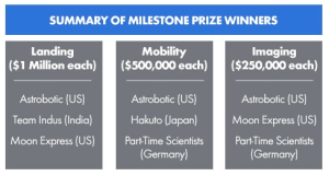
  • Milestone prizes: $5.25 million already has been awarded to teams that demonstrated robust hardware in three categories: landing, mobility, and imaging. The following Milestone prize winners have been announced:

Milestone prize winnersSource: XPrize

  • Bonus prizes: Up to $4 million for successfully completing additional scientific and technical tasks not in the mission requirements
  • Apollo Heritage Bonus Prize: $4 million for making an Apollo Heritage Mooncast from the site of an Apollo moon landing.
  • Heritage Bonus Prize: $1 million for making a Mooncast from another site of interest to XPrize.
  • Range Bonus Prize: $2 million for a rover that can traverse five kilometers on the Moon’s surface.
  • Survival Bonus Prize: $2 million for successfully operating on two separate lunar days.
  • Water Detection Bonus Prize: $4 million for producing scientifically conclusive proof of the presence of water on the Moon.

The Google Lunar XPrize home page is at the following link, where you can navigate to many details on this competition and sign up for an XPrize newsletter:

http://lunar.xprize.org

The Google Lunar XPrize began with 29 teams and now 16 remain. As noted above, five teams already have won Milestone prizes.

The three teams that competed in the landing milestone competition are taking different approaches. Astrobotics is using a lunar lander developed by Masten Aerospace. Indus and Moon Express are developing their own lunar landers.

So far, only two teams have launch contracts:

  • On 7 October 2015, the Israeli team SpaceIL became the first Lunar XPrize team to sign a launch contract. They signed a launch services contract with Spaceflight Industries for launch on a SpaceX Falcon 9 launcher in the second half of 2017.
  • On 8 December 2017, XPrize verified the Moon Express launch contract with Rocket Lab USA. Moon Express contracted for three launches using an Electron booster, which, as of mid-2016, is still being developed.

By the end of 2016, all competitors that intend to continue into the finals must have a launch contract in place.

So far, only three nations have made a soft landing on the Moon: USA, Russia and China. In 2017, a privately funded team may be added to that list.  That would be a paradigm shift for lunar exploration, opening the door for private teams and commercial firms to have regular, relatively low cost access to the Moon.

Update 23 December 2016: Google Lunar XPrize Status

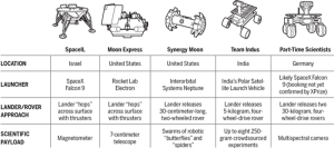
On 22 December 2016, author Daniel Clery posted an article, “Here’s who could win the $20 million XPrize for roving on the moon—but will any science get done?” The author reports that six teams claim to have booked flights to the moon for their lunar landers / rovers. The following chart provides a summary for five of the competitors. The small (4 kg) rover for the sixth competitor, Japan’s Team Hakuto, will be delivered to the moon on the same lander as India’s Team Indus.

LunarXPrixe competitors Dec 2016

Click on the graphic above to enlarge. Source: G. Grullón/Science

As I noted previously, all competitors that intend to continue into the Lunar XPrize finals must have a launch contract in place by the end of 2016, and the mission to the moon must be completed by the end of 2017.

You can read Daniel Clery’s complete article on the Sciencemag.org website, at the following link:

http://www.sciencemag.org/news/2016/12/heres-who-could-win-20-million-xprize-roving-moon-will-any-science-get-done?utm_campaign=news_daily_2016-12-22&et_rid=215579562&et_cid=1068715

Update 23 January 2018: Google Lunar XPrize Competion Cancelled

After concluding that none of the remaining competitors could meet the extended 31 March 2018 deadline for landing on the Moon, this competition came to a close, with the $30M in prizes remaining unclaimed.

Post-World War II Prefabricated Aluminum and Steel Houses and Their Relevance Today

This 3 August 2016 post was replaced on 15 June 2020 with my updated and expanded post with the same title, “Post-World War II Prefabricated Aluminum and Steel Houses and Their Relevance Today,” which is available at the following link:

https://lynceans.org/all-posts/post-world-war-ii-prefabricated-aluminum-and-steel-houses-and-their-relevance-today-2/

The updated and expanded resource document provides a brief overview of the post-WW II housing crisis in the US, UK and France, and the efforts in these nations to help resolve the housing crisis with mass-produced, prefabricated aluminum and steel houses.  It also provides links to 13 individual, downloadable articles I prepared on specific types of post-WW II prefabricated aluminum and steel houses manufactured in the US, UK and France.

I hope you’ll find the new post to be informative, useful and different from any other single source on the subject.

Best regards,

Peter Lobner

15 June 2020

DARPA Cyber Grand Challenge (CGC)

Peter Lobner

DARPA launched the Cyber Grand Challenge (CGC) in 2014. This is a competition in which each competitor team attempts to create an automatic IT network defense system that can analyze its own performance during attacks by an intelligent adversaries, identify security flaws, formulate patches, and deploy the patches in real-time on the network being protected. This DARPA competition will “give these groundbreaking prototypes a league of their own, allowing them to compete head-to-head to defend a network of bespoke software.”

The longer-term DARPA goal is to promote technology that leads to operational, automatic, scalable, adaptive, network defense systems operating at machine speed to protect IT networks against intelligent adversaries.

The CGC Challenge Competitor Portal is at the following link:

https://cgc.darpa.mil

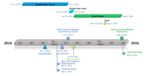
The Master Schedule for CGC is shown in the following chart:

CGC Master ScheduleSource: DARPA

A slide presentation reporting the lessons learned from the first year of the CGC is available at the following link:

https://www.usenix.org/sites/default/files/conference/protected-files/sec15_slides_walker.pdf

This is a complex slide presentation that benefits greatly from seeing it along with a video of the actual presentation made by Mike Walker at the 12 – 14 August 2015 24th USENIX Security Symposium. You will find this rather long (1 hour 17 min) video at the following link:

https://www.usenix.org/node/190798

In the 2015 Challenge Qualification Event, seven finalists were qualified. The finals will be held from 54 August 2016 at the Paris Hotel & Convention Center in Las Vegas, Nevada. The Award Ceremony will be held at the beginning of DEF CON 24 on Friday, 5 August 2016.
CGCEventFirstAutomatedNetDefense  Source: DARPA

This is exciting stuff! The results are certain to be very interesting.

8 August 2016 Update: Carnegie Mellon’s Mayhem computer system won DARPA’s CGC
Seven invited teams competed for $4 million in prizes at the DARPA CGC. The $2 million grand prize winner was the Mayhem computer system designed by Carnegie Mellon’s team ForAllSecure. The $1 million second place prize was awarded to the Xandra computer system designed by team TECHx of Ithaca, NY, and Charlottesville, VV. Third place and a $750K prize was awarded to the Mechanical Phish computer system developed by the Shellphish team of Santa Barbara, CA.
You can read details on the DARPA website at the following link:

http://www.darpa.mil/news-events/2016-08-05a

Also see the following article on the TechCrunch website for more details on the CGC Finals competition.

https://techcrunch.com/2016/08/05/carnegie-mellons-mayhem-ai-takes-home-2-million-from-darpas-cyber-grand-challenge/

Where Earth-orbiting Satellites go to Die

Updated 30 April 2020

Peter Lobner

For satellites large enough to generate reentry debris that can reach the surface of the Earth, there are four choices: Manitowoc, WI, the Spacecraft Cemetery, a Graveyard Orbit, or the Space Garbage Truck. Let’s look at these alternatives.

Korabi-Sputnik 1 (aka Sputnik 4) was launched by the Soviet Union on 15 May 1960 and was reported to be a test of an orbital spacecraft with a recoverable, pressurized capsule capable of carrying a cosmonaut. At the time of its launch, Sputnik 4 was the largest satellite placed in orbit, with a weight of at least 5 tons.

Koralb_sputnikSource: pics-about-space.com

Sputnik 4 appears to have been a prototype of the Soviet Vostok spacecraft that carried the first human, Yuri Gagarin, into orbit on 12 April 1961.

Vostok_diagram Source: Space.com, graphics by Karl Tate

Due to a failure in the control or reentry system, the Sputnik 4 capsule did not return to Earth as planned, but instead, remained in orbit until 5 September 1962. On that day, Sputnik 4 reentered the Earth’s atmosphere and broke up, with fragments landing in Lake Michigan and in downtown Manitowoc, WI. The following diagram from the 3 December 1962 issue of Aviation Week magazine shows the paths for Sputnik 4 fragments that landed on the main street of Manitowoc, Wisconsin.

Sputnik 4 reentry over Manitowoc_5

On a recent trip, I visited the site in Manitowoc where a large, hot fragment landed and embedded itself into the asphalt pavement of a main street. That site is commemorated by a brass ring in the street and a granite plaque on the sidewalk.

Sputnik 4 landed hereSource: Author’s photos 

The Sputnik 4 debris was analyzed by the U.S. and then returned to the Soviet Union. The following photos from the 3 December 1962 issue of Aviation Week magazine show details of the largest fragment.

Sputnik 4 fragment photo 1

Sputnik 4 fragment photo 2

The Smithsonian Institution made two reproductions of this large fragment. Today, both reproductions normally are in Manitowoc; one at the Rahr-West Art Museum (on loan to a Green Bay museum on the day of my visit) and the other at the Manitowoc Visitor’s Center. Here’s a photo of the reproduction at the Visitor’s Center.

Sputnik 4 fragment DSC03294Source: Author’s photo

You can read more about Sputnik 4 in the article, “Sputnik Crashed Here,” at the following link:

http://www.roadsideamerica.com/story/12959

Many small satellites have reentered the Earth’s atmosphere at end-of-life and burned up completely, without debris reaching the Earth’s surface. No special end-of-life procedures are needed to manage the retirement of such small satellites.

Today, there is a systematic process for de-orbiting larger satellites in low Earth orbit that can produce reentry debris capable of reaching the Earth’s surface. NASA reports:

“There is a solution—spacecraft operators can plan for the final destination of their old satellites to make sure that any debris falls into a remote area. This place even has a nickname—the Spacecraft Cemetery! It’s in the Pacific Ocean and is pretty much the farthest place from any human civilization you can find.”

Spacecraft-cemeterySource: NASA

NASA has developed plans for de-orbiting the >500 ton International Space Station (ISS) at the end of its operational life, which is expected to last until at least 2028. There also is a plan to de-orbit the ISS if it must be evacuated in an emergency and cannot be recovered. You’ll find more information on NASA’s plans at the following link:

https://www.nasaspaceflight.com/2013/08/bringing-down-iss-plans-stations-demise-updated/

When the time comes, ISS reentry will be targeted for the Spacecraft Cemetery.

Spacecraft in higher orbits, including geosynchronous orbit, commonly are maneuvered into “graveyard orbits” where they are retired, outside the orbits of other active satellites. Here they will remain for a very long time without significant risk of interfering with active satellites or de-orbiting in an uncontrolled reentry.  

An example is the Lincoln Experimental Satellite 5 (LES-5), which was developed by the MIT Lincoln Laboratory and launched into synchronous orbit in 1967 to test satellite-based ultra-high frequency (UHF) secure communications for US military users.  The solar-powered LES-5 remained active until May 1971 after which it was decommissioned and moved to a higher graveyard orbit in 1972.  On 24 March 2020, Scott Tilley, an amateur radio operator living in British Columbia, announced that he had located a signal from the LES-5 satellite at 237 MHz, transmitting at about 100 bits/sec from its graveyard orbit.  You’ll find more details on the “re-discovery” of LES-5 here:

https://www.popularmechanics.com/space/satellites/a32293223/les-5-satellite/

A new option is under development by the European Space Agency (ESA), which launched the Clean Space Initiative in 2013 to address the great amount of debris and dead satellites in Earth orbit.  ESA reported:

“Scientists estimate the total number of space debris objects in orbit to be around 29 000 for sizes larger than 10 cm, 670 000 larger than 1 cm, and more than 170 million larger than 1 mm.

Any of these objects can cause harm to an operational satellite. For example, a collision with a 10 cm object would entail a catastrophic fragmentation of a typical satellite, a 1 cm object will most likely disable a spacecraft and penetrate the International Space Station shields, and a 1 mm object could destroy subsystems. Scientists generally agree that, for typical satellites, a collision with an energy-to-mass ratio exceeding 40 J/g would be catastrophic.”

The ESA’s warning signs posted in orbit proved to be ineffective.

No littering in orbit  Source:  How-to Geek Newsletter

Therefore, ESA is planning a more ambitious mission called e.DeOrbit for removing space debris.  For its demonstration mission, the ESA e.DeOrbit spacecraft is being designed to capture debris in polar orbit between 800 – 1,000 km (497 – 621 miles) altitude. Various concepts are being considered to capture the intended orbital target, including nets, arms, and tentacles. Once captured, the e.DeOrbit spacecraft will maneuver the combined satellite (target + e.DeOrbit) into a controlled reentry. The first launch of an e.DeOrbit garbage truck is expected to be in the 2023 time frame.

ESA eDeOrbit nete.DeOrbit capture using a net. Source: ESA

ESA eDeOrbit armse.DeOrbit capture using arms. Source: ESA

You can read more on the ESA Clean Space Initiative and the e.DeOrbit mission at the following links:

http://www.esa.int/Our_Activities/Space_Engineering_Technology/Clean_Space/How_to_catch_a_satellite

and

http://iaassconference2013.space-safety.org/wp-content/uploads/sites/28/2013/06/1200_Biesbroek_Innocenti.pdf

2015 International Technology Roadmap for Semiconductors (ITRS) and Moore’s Law

Peter Lobner

On 8 July 2016, the Semiconductor Industry Association (SIA) and its international partners announced the release of the 2015 International Technology Roadmap for Semiconductors (ITRS), which it describes as follows:

ITRS is “a collaborative report that surveys the technological challenges and opportunities for the semiconductor industry through 2030. The ITRS seeks to identify future technical obstacles and shortfalls, so the industry and research community can collaborate effectively to overcome them and build the next generation of semiconductors – the enabling technology of modern electronics.”

ITRS report coverYou can download the 2015 ITRS Executive Report and the seven technical sections at the following link:

http://www.semiconductors.org/main/2015_international_technology_roadmap_for_semiconductors_itrs/

Key points from the Executive Report are the following:

  • Economic gains from adopting manufacturing processes and packaging for smaller transistors are decreasing.
    • The magnitude of the investment needed for developing the processes and devices for manufacturing the highest performance chips has reduced the number of top-tier manufacturers (IC foundries) to just four.
  • Advanced manufacturing technologies exist for increasing transistor density, including smaller 2D features and 3D (stacked) features.
    • As features approach 10 nm (nanometers), the IC manufacturers are running out of horizontal space.
    • Flash memory is leading the way in 3D manufacturing to enable higher packing densities.
  • As packing densities continue to increase, new techniques will be needed by about 2024 to ensure adequate heat removal from the highest density chips.
    • At some point, liquid cooling may be required.
  • Companies without fabrication facilities (i.e., Apple) are producing the IC design, which is manufactured by a foundry company (i.e., Samsung manufactures the Apple A6X IC).
  • A new “ecosystem” has evolved in the past decade that is changing the semiconductor industry and blurring the way that performance scaling is measured.
    • Manufacturing advances enable further miniaturization of IC features and the integration of digital system functions (i.e., logic, memory, graphics, and other functionality) in a single die (system-on-a-chip, SOC). This is known as “More Moore” (MM).
    • System integration and packaging advances enable multiple related devices (i.e., power & power management, interfaces with the outside world) to be integrated in a single package along with the IC (system-in-package, SIP). This is known as “More-than-Moore” (MtM).
    • You can see the distinction between MM and MtM in the following diagram from the IRTS white paper, “More-then-Moore,” by Wolfgang Arden, et al., http://www.itrs2.net/uploads/4/9/7/7/49775221/irc-itrs-mtm-v2_3.pdf

More than Moore fig 1

The transition to computationally intensive cloud computing enables effective use of “big data”. In contrast, there has been a proliferation of smart, low-power, functionally diverse devices that generate or use instant data, and can be linked to the cloud as part of the Internet of Things (IoT). These different ends of the spectrum (cloud & IoT) create very different demands on the semiconductor industry. They also complicate measurement of industry performance. It’s not just Moore’s Law anymore.

Big data & instant data

The 2015 IRTS offers an expanded set of metrics to assess the combined performance of SoC and SIP in delivering higher value systems. This measurement scheme is shown conceptually below (from the same IRTS “More-then-Moore” white paper cited above).

More than Moore fig 2

For another perspective on the 2015 ITRS report, you can read a short article by Sebastian Anthony on the arsTECHNICA website at the following link:

http://arstechnica.com/gadgets/2016/07/itrs-roadmap-2021-moores-law/?mbid=synd_digg&utm_source=howtogeek&utm_medium=email&utm_campaign=newsletter