Festo is a German multinational industrial control and automation company based in Esslingen am Neckar, near Stuttgart. The Festo website is here: https://www.festo.com/group/en/cms/10054.htm
Festo reports that they invest about 8% of their revenues in research and development. Festo’s draws inspiration for some of its control and automation technology products from the natural world. To help facilitate this, Festo established the Bionic Learning Network, which is a research network linking Festo to universities, institutes, development companies and private inventors. A key goal of this network is to learn from nature and develop “new insights for technology and industrial applications”…. “in various fields, from safe automation and intelligent mechatronic solutions up to new drive and handling technologies, energy efficiency and lightweight construction.”
One of the challenges taken on by the Bionic Learning Network was to decipher how birds fly and then develop robotic devices that can implement that knowledge and fly like a bird. Their first product was the 2011 SmartBird and their newest product is the 2020 BionicSwift. In this article we’ll take a look at these two bionic birds and the significant advancements that Festo has made in just nine years.
2. SmartBird
On 24 March 2011, Festo issued a press release introducing their SmartBird flying bionic robot, which was one of their 2011 Bionic Learning Network projects. Festo reported:
“The research team from the family enterprise Festo has now, in 2011, succeeded in unraveling the mystery of bird flight. The key to its understanding is a unique movement that distinguishes SmartBird from all previous mechanical flapping wing constructions and allows the ultra-lightweight, powerful flight model to take off, fly and land autonomously.”
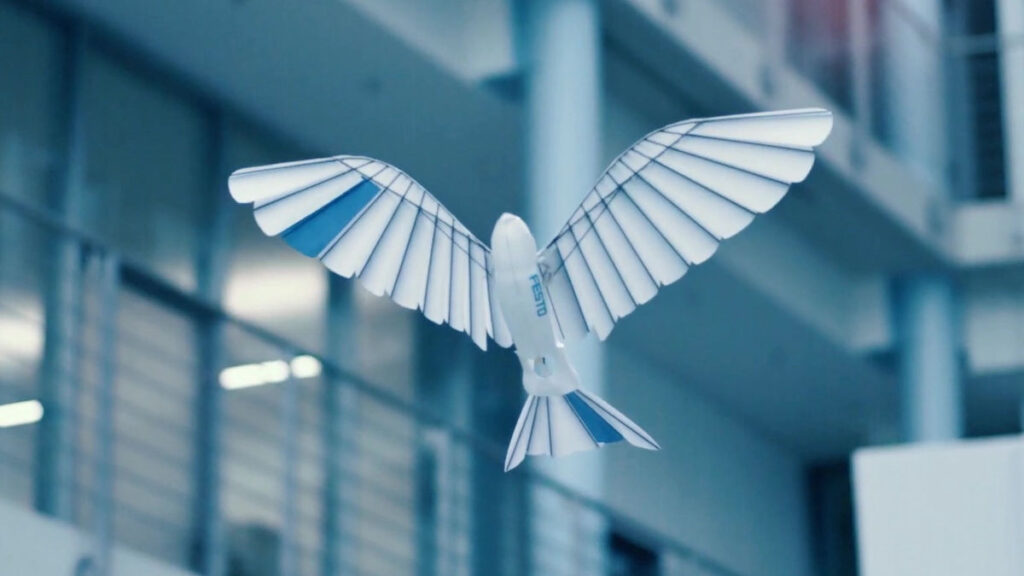
“SmartBird flies, glides and sails through the air just like its natural model – the Herring Gull – with no additional drive mechanism. Its wings not only beat up and down, but also twist at specific angles. This is made possible by an active articulated torsional drive unit, which in combination with a complex control system makes for unprecedented efficiency in flight operation. Festo has thus succeeded for the first time in attaining an energy-efficient technical adaptation of this model from nature.”
SmartBird measures 1.07 meters (42 in) long with a wingspan of 2.0 meters (79 in) and a weigh of 450 grams (16 ounces, 1 pound). This is about a 1.6X scale-up in the length and span of an actual Herring Gull, but at about one-third the weight. It is capable of autonomous takeoff, flight, and landing using just its wings, and it controls itself the same way birds do, by twisting its body, wings, and tail. SmartBird’s propulsion system has a power requirement of 23 watts.
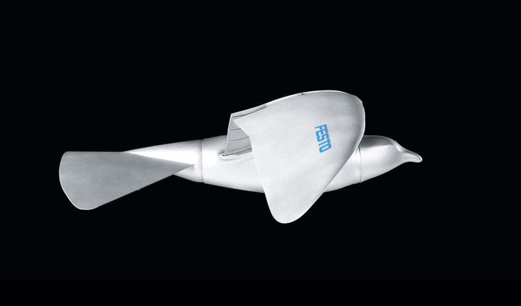
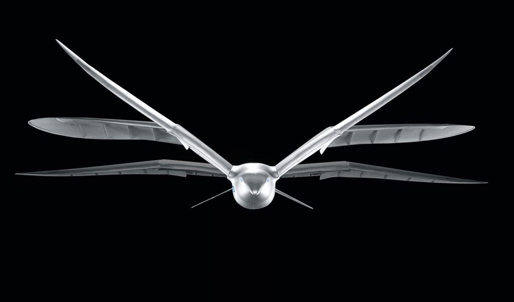
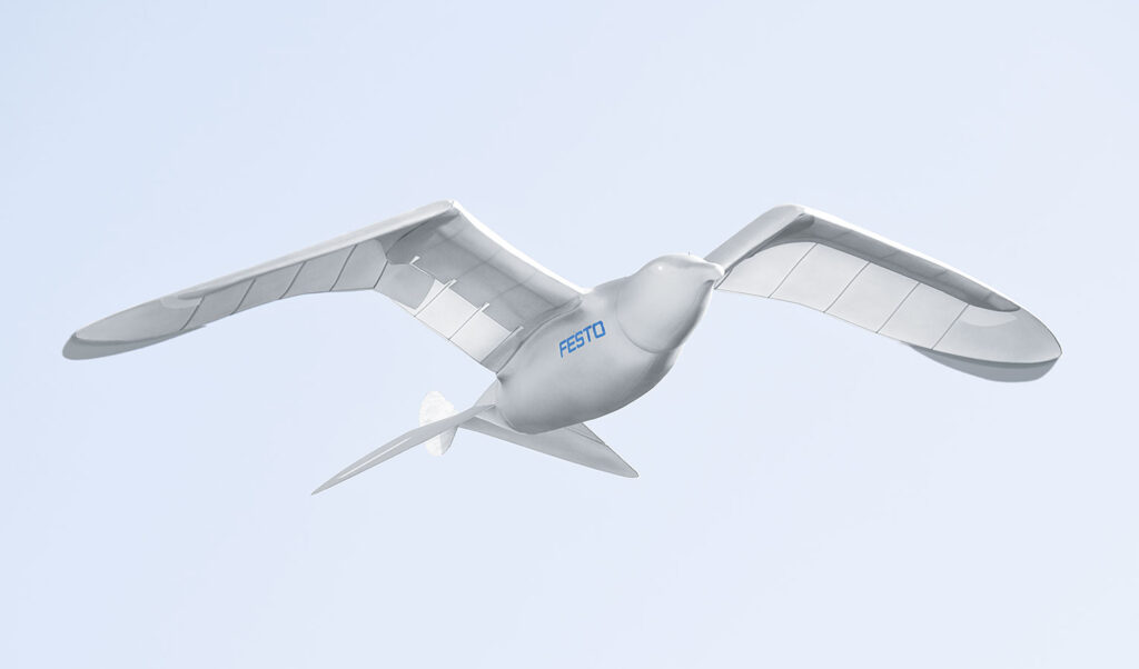
On 1 July 2020, Festo introduced the BionicSwift as their latest ultra light flying bionic robot that mimics how actual birds fly.
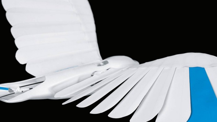
The BionicSwift, inspired by a Common Swift, measures 44.5 cm (17.5 in) long with a wingspan of 68 cm (26.7 in) and a weight of just 42 grams (1.5 ounces). It’s approximately a 2X scale-up of a Common Swift, but still a remarkably compact, yet complex flying machine with aerodynamic plumage that closely replicates the flight feathers on an actual Swift. The 2011 SmartBird was more than twice the physical size and ten times heavier.
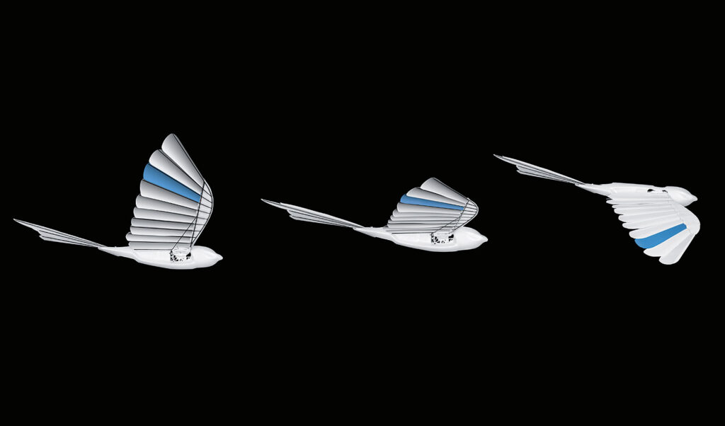
The BionicSwift is agile, nimble and can even fly loops and tight turns. Festo reports: “Due to this close-to-nature replica of the wings, the BionicSwifts have a better flight profile than previous wing-beating drives.” Compare the complex, feathered wing structure in the following Festo photos of the BionicSwift with the previous photos showing the simpler, solid wing structure of the 2011 SmartBird.
Source: All three BionicSwift photos from Festo
A BionicSwift can fly singly or in coordinated flight with a group of other BionicSwifts. Festo describes how this works: “Radio-based indoor GPS with ultra wideband technology (UWB) enables the coordinated and safe flying of the BionicSwifts. For this purpose, several radio modules are installed in one room. These anchors then locate each other and define the controlled airspace. Each robotic bird is also equipped with a radio marker. This sends signals to the anchors, which can then locate the exact position of the bird and send the collected data to a central master computer, which acts as a navigation system.” Flying time is about seven minutes per battery charge.
4. For more information about other Festo bionic creations:
I encourage you to visit the Festo BionIc Learning Network webpage at the following link and browse the resources available for the many intriguing projects. https://www.festo.com/group/en/cms/10156.htm
On this webpage you’ll find a series of links listed under the heading “More Projects,” which will introduce you to the wide range of Bionic Learning Network projects since 2006.
You also can watch the following YouTube short videos of Festo’s many bionic creations:
BionicFinWave (2018):replicates the swimming movements of sea creatures with undulating fins to create a unique fin drive system for an autonomous underwater vehicle: https://www.youtube.com/watch?v=fRNq55EbnZc
AirRay (2010): replicates the natural underwater movements of a Manta Ray in a larger-than-life, neutrally buoyant, ray-shaped airship with a flapping wing drive: https://www.youtube.com/watch?v=c3-wIICjAhE
AquaRay (2010): replicates the natural underwater movements of a Manta Ray in a full-size autonomous underwater vehicle with a flapping wing drive: https://www.youtube.com/watch?v=F4-6oNagIvk
AirPenguin (2009): replicates the natural underwater movements of a penguin in a larger-than-life, neutrally buoyant, penguin-shaped airship: https://www.youtube.com/watch?v=jPGgl5VH5go
AquaPenguin (2009): replicates the natural underwater movements of a penguin in a small penguin-sized autonomous underwater vehicle: https://www.youtube.com/watch?v=u8tfES8gImc
AirJelly (2008): replicates the natural underwater movements of a jelly fish in a larger-than-life, neutrally buoyant, jelly fish-shaped airship: https://www.youtube.com/watch?v=divLsTtA5vk
AquaJelly (2008): replicates the natural underwater movements of a jelly fish in a small, autonomous, peristaltic drive autonomous underwater vehicle that can operate in coordination with several other AquaJellies: https://www.youtube.com/watch?v=N-O8-N71Qcw
Peter Lobner, updated 23 February 2026 (post-Rev. 6)
1. Introduction
Modern Airships is a three-part document that contains an overview of modern airship technology in Part 1 and links in Parts 1, 2 and 3 to more than 285 individual articles on historic and advanced airship and aerostat designs. This is Part 2. Here are the links to the other two parts:
To help you navigate the large volume of material in these three documents, please refer to following indexes. The first index simply lists the article titles in alphabetic order within each Part.
Parts 1 & 2 address similar types of airships and unpowered aerostats. The following airship type index enables you to see all of the airships and aerostats addressed in Parts 1 & 2, grouped by type, with direct links to the relevant articles.
The airships described in Part 3 are relatively exotic concepts in comparison to the more utilitarian and heavy-lift airships that dominate Parts 1 and 2. As shown in the following index, the airships in Part 3 are organized by function rather than airship type, which sometimes is difficult to determine with the information available.
Modern Airships – Part 2 begins with a set of graphic tables that identify the airships addressed in this part, and concludes by providing links to more than 120 individual articles on those airships. A downloadable pdf copy of Part 2 (Rev. 6) is available here:
Each of the linked articles can be individually downloaded.
If you have any comments or wish to identify errors in these documents, please send me an e-mail to: PL31416@cox.net.
I hope you’ll find the Modern Airships series to be informative, useful, and different from any other single document on this subject.
Best regards,
Peter Lobner
23 February 2026
Record of revisions to Part 2
Original Modern Airships post, 26 August 2016: addressed 14 airships in a single post.
Expanded the Modern Airships post and split it into three parts, 18 August 2019: Part 2 included 25 articles
Part 2, Revision 1, 21 December 2020: Added 2 new articles on Walden Aerospace. Part 2 now had 27 articles
Part 2, Revision 2, 3 April 2021: Added 35 new articles, split the original variable buoyancy propulsion article into three articles, and updated all of the original articles. Also updated and reformatted the summary graphic table. Part 2 now had 64 articles.
Part 2, Revision 3, 9 September 2021: Updated 7 articles. Added category for “thermal (hot air) airships” and added pages for them in the summary graphic table. Part 2 still had 64 articles.
Part 2, Revision 4, 11 February 2022: Added 26 new articles, expanded the graphic tables and updated 12 existing articles. A detailed summary of changes incorporated in Part 2, Rev 4 is listed here. Part 2 now had 90 articles.
Part 2, Revision 5, 10 March 2022: Added 1 new article, split rigid & semi-rigid airships in the graphic tables, and updated 52 existing articles. With this revision, all Part 2 linked articles have been updated in February or March 2022. A detailed summary of changes incorporated in Part 2, Rev 5 is listed here. Part 2 now has 91 articles.
Part 2, Revision 6, 17 March 2024: This revision includes a major reorganization of Parts 1 & 2 to better aggregate airships and unpowered aerostats by type, with a corresponding reorganization of the graphic tables. Over the past two years, 28 new articles were added to Part 2 and 27 articles were updated. In the final changes for Rev. 6, several articles were moved between Parts 1 & 2. A detailed summary of changes incorporated in Part 2, Rev 6 is listed here. Part 2 now has 117 articles.
Part 2, changes since Rev. 6 (17 March 2024)
New articles:
Altaeros Energies Inc. – Buoyant Air Turbine (BAT) – 31 October 2024
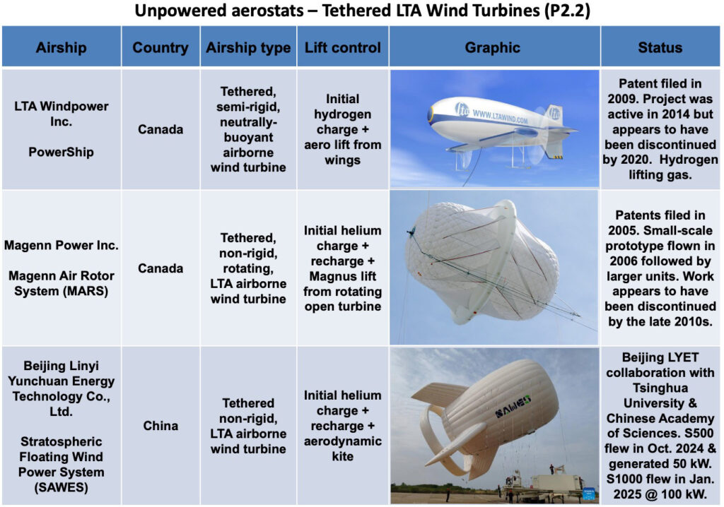
Beijing Linyi Yunchuan Energy Technology Co., Ltd. – Stratospheric Floating Wind Power System (SAWES) – 31 October 2024
Magenn Power Inc. – Magenn Air Rotor System (MARS) – 31 October 2024
Stratoship – Australian HAPS airship – 29 August 2025
Troponaut – Rigid airship – 23 February 2026
Updated articles:
Flying Whales – 24 June 2024
China’s Aerospace Research Institute – Jimu No. 1, Type III, high-altitude tethered aerostat – 13 September 2024
LTA Aerostructures (LTAA) – rigid airships – 6 November 2024
Beijing Linyi Yunchuan Energy Technology Co., Ltd. – Stratospheric Floating Wind Power System (SAWES) – 17 January 2025 & 30 September 2025
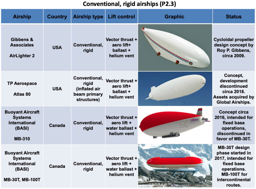
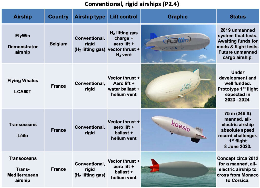
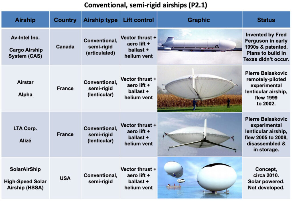
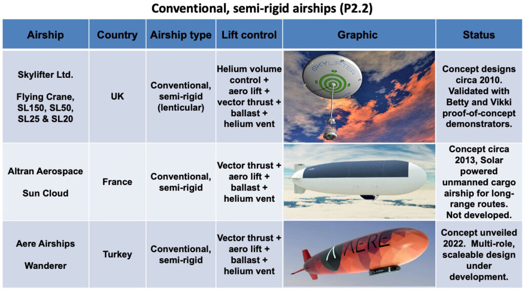
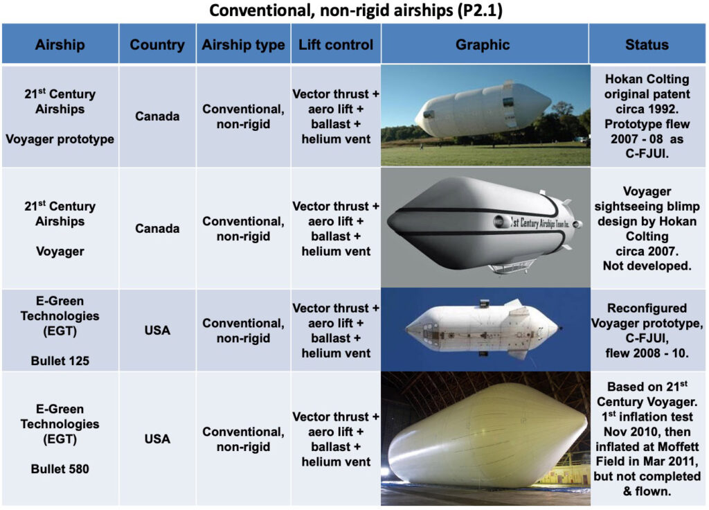
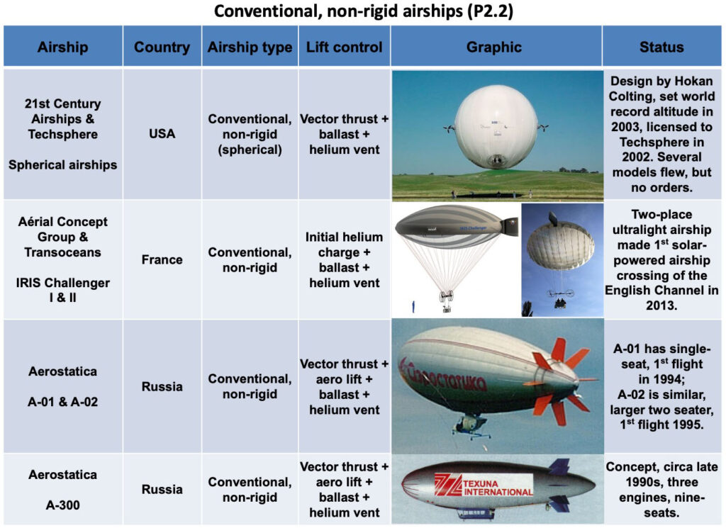
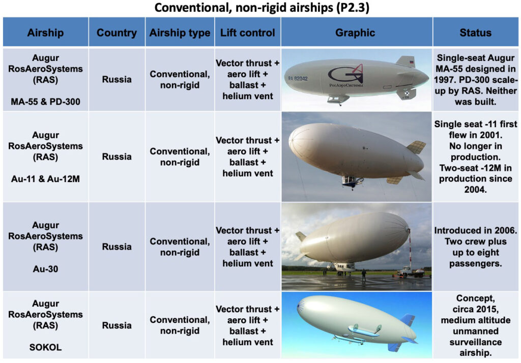
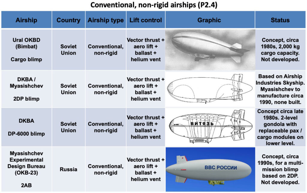
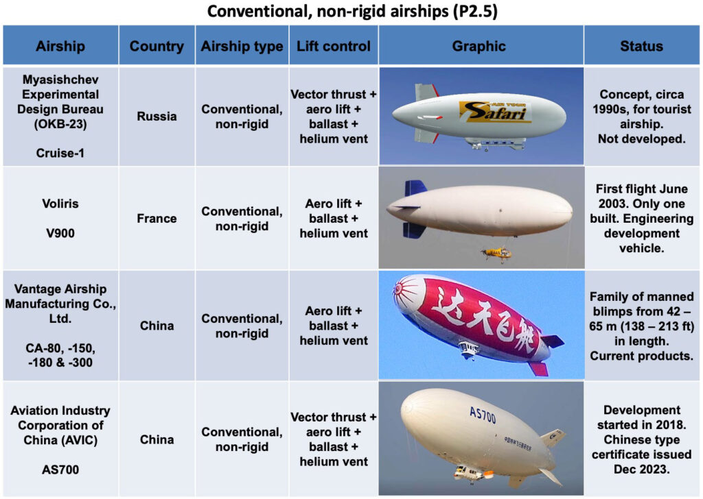
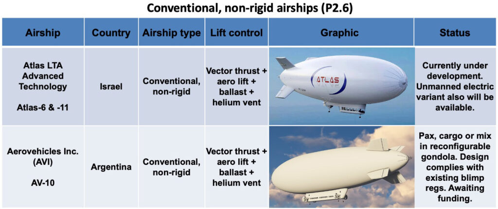
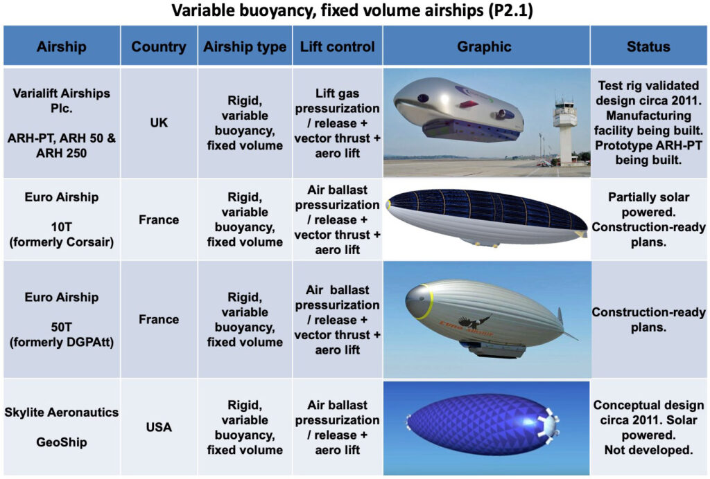
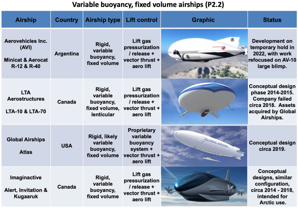
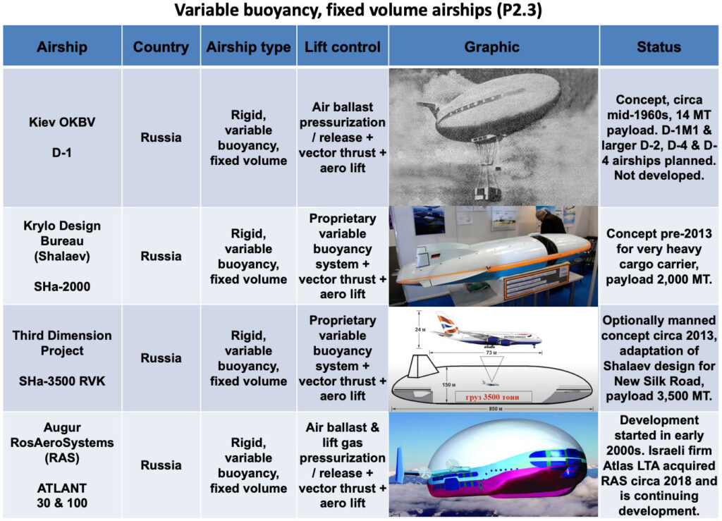
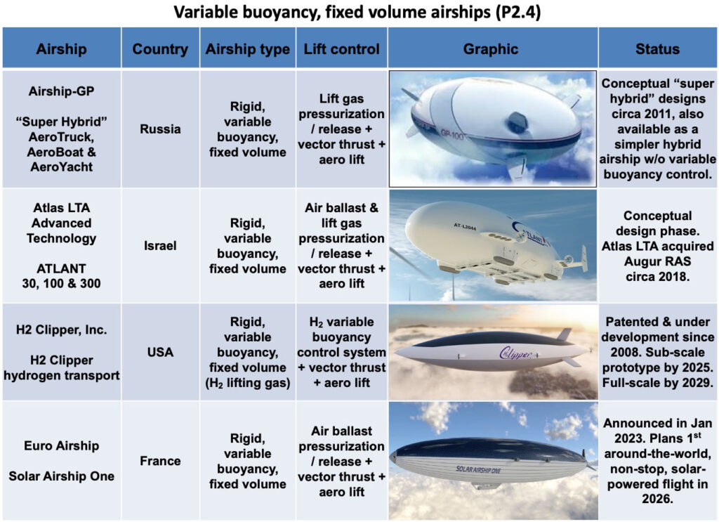
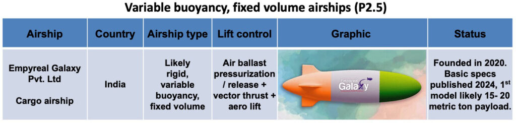
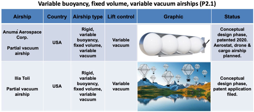
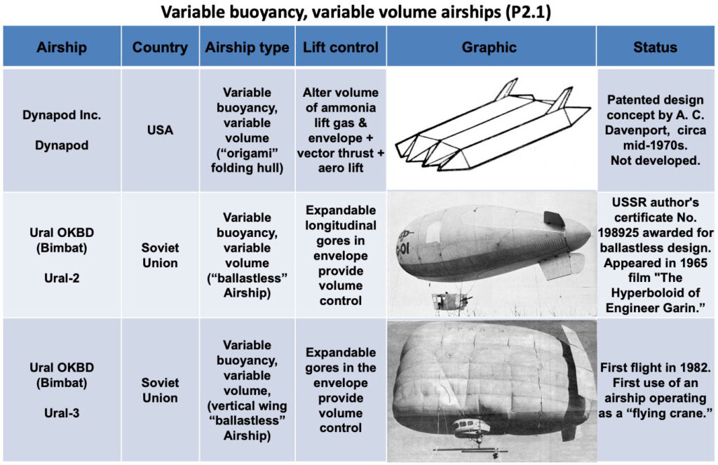
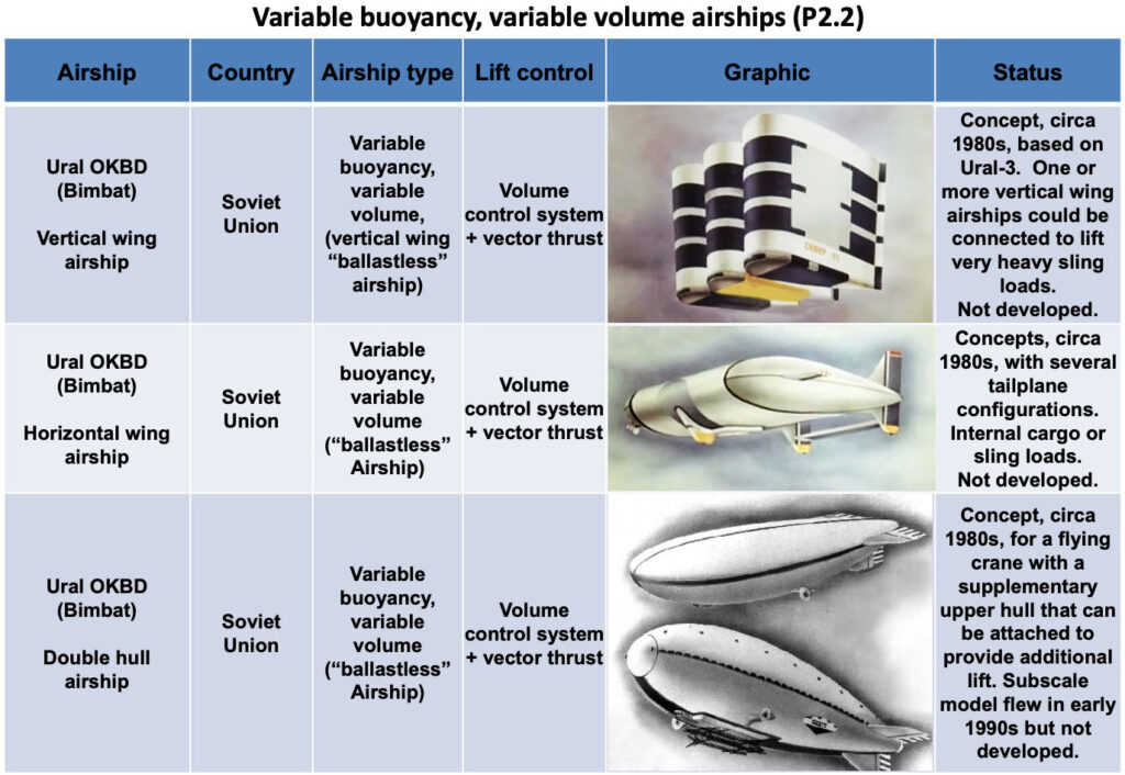
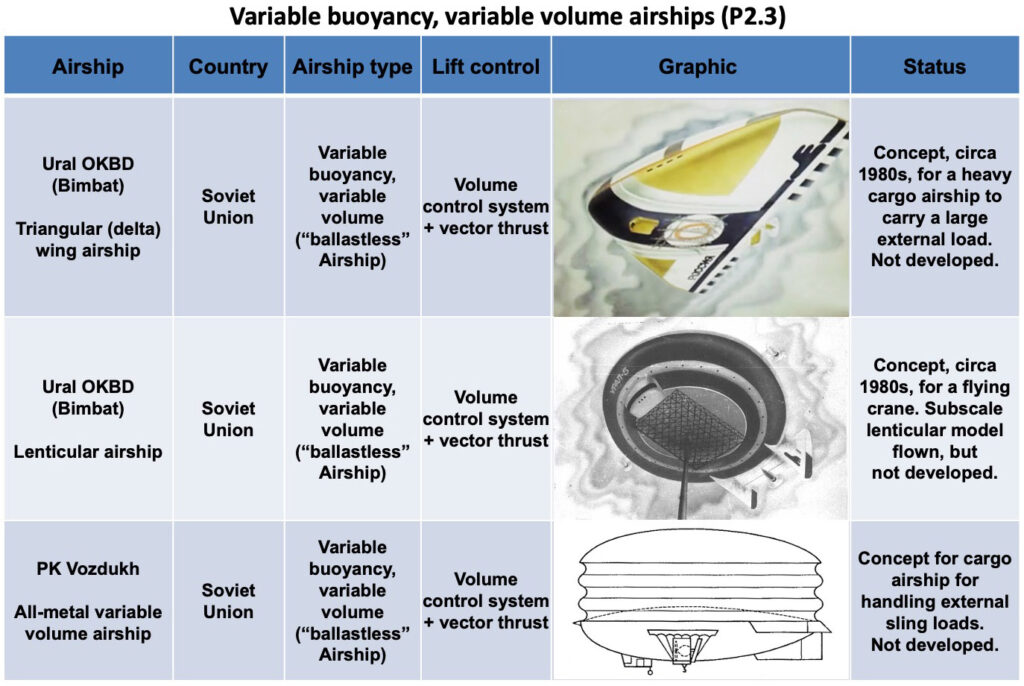
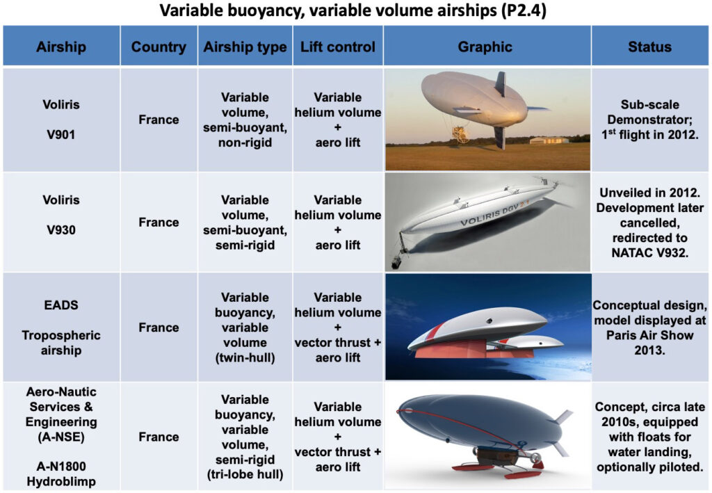
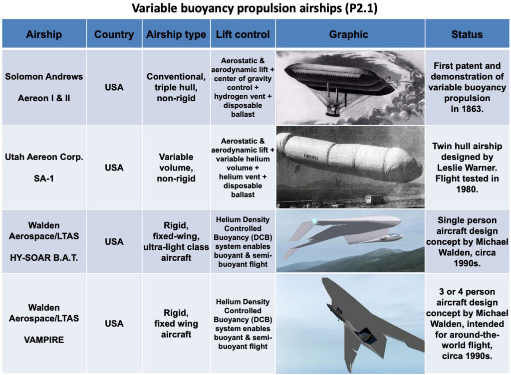
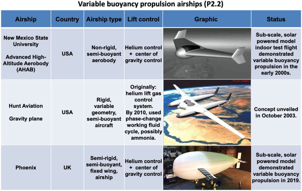
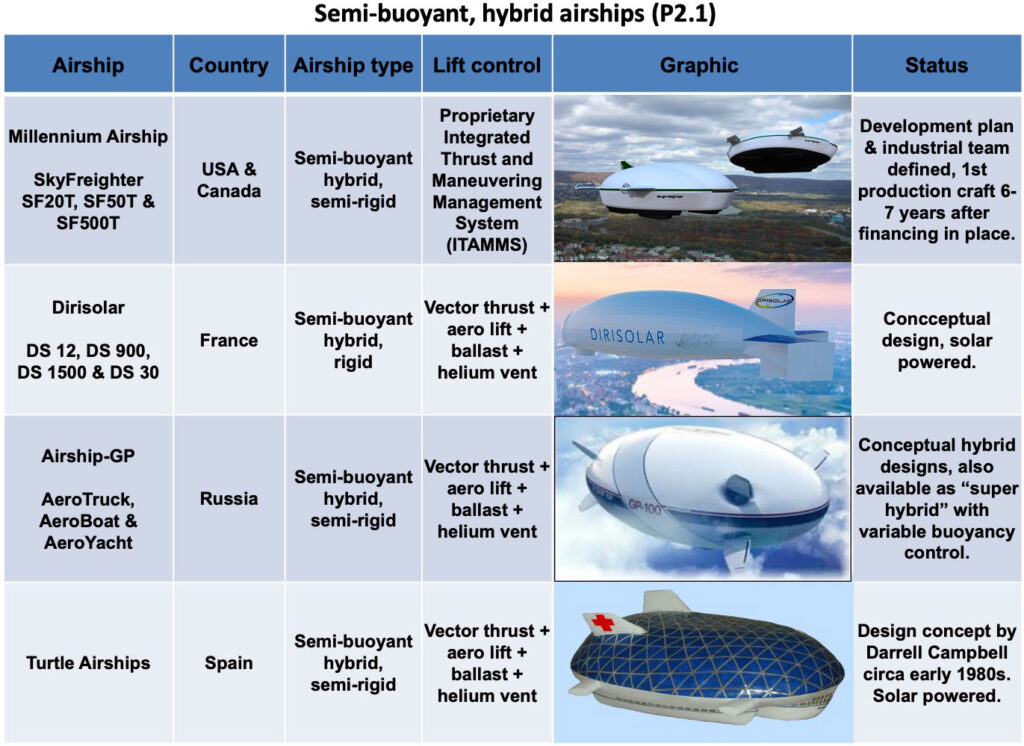
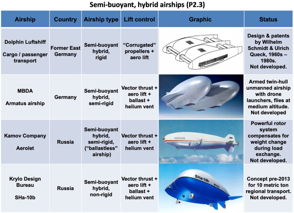
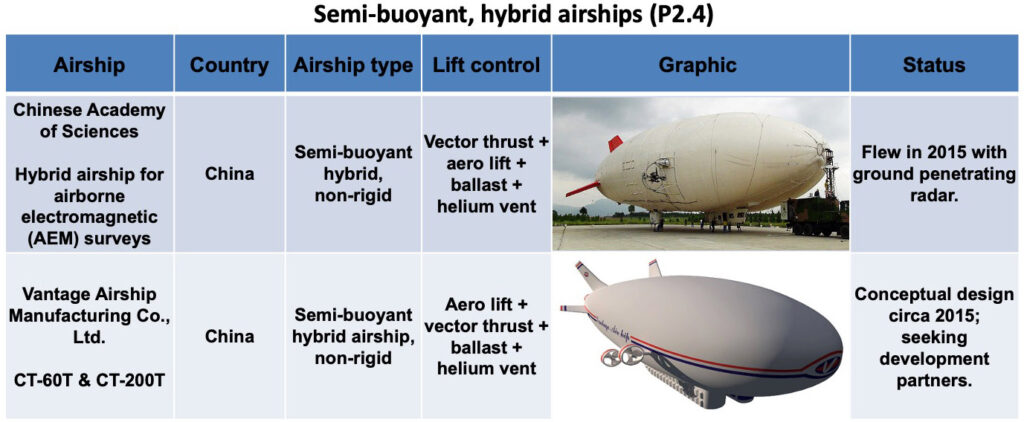
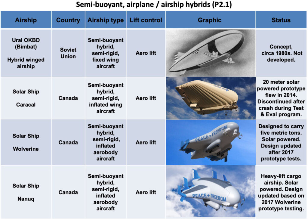
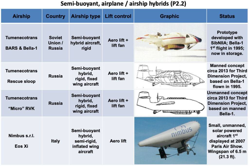
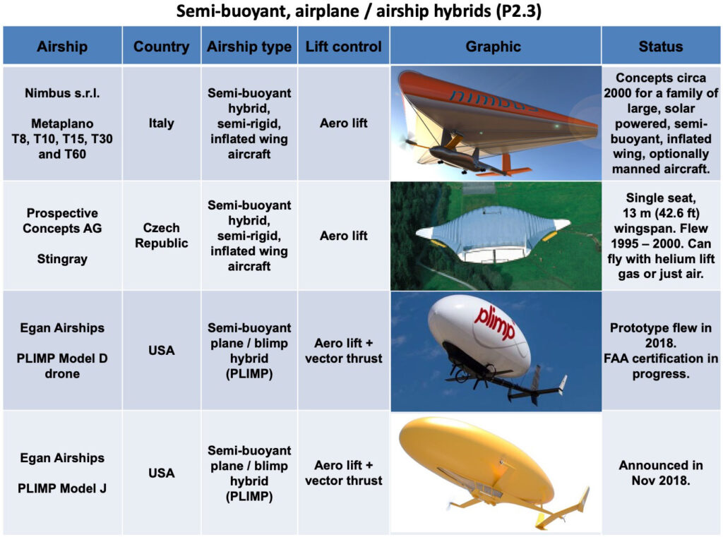
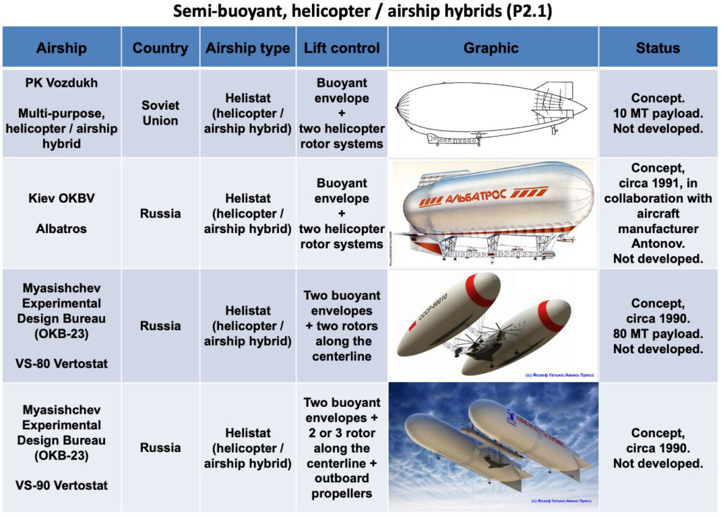
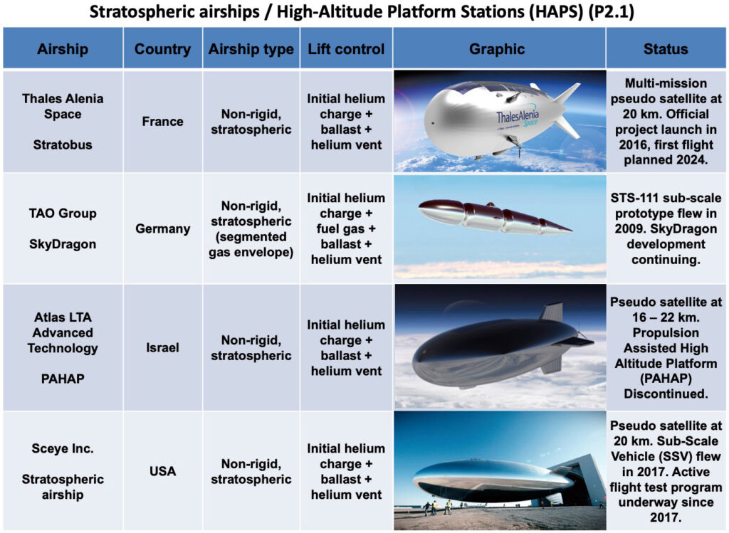
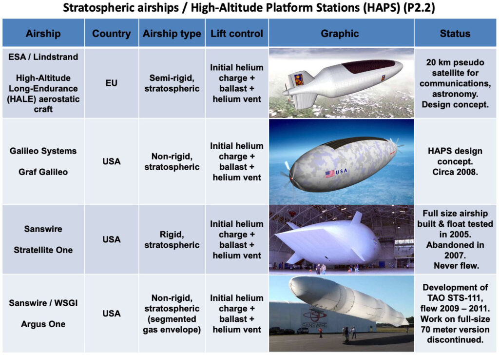
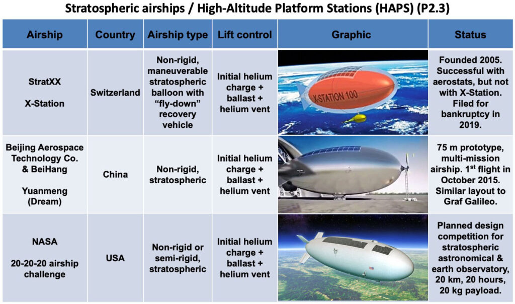
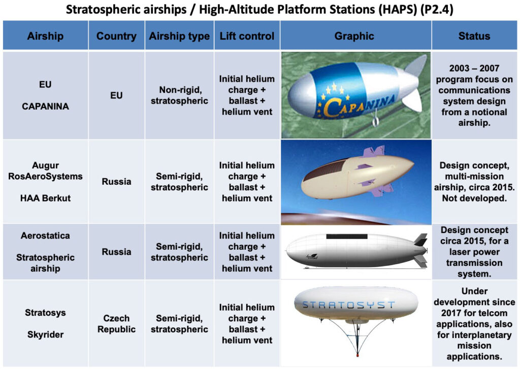
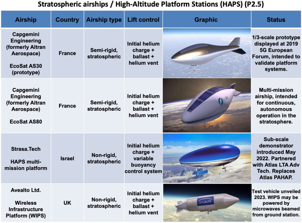
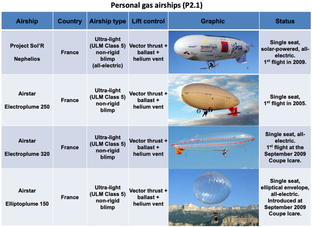
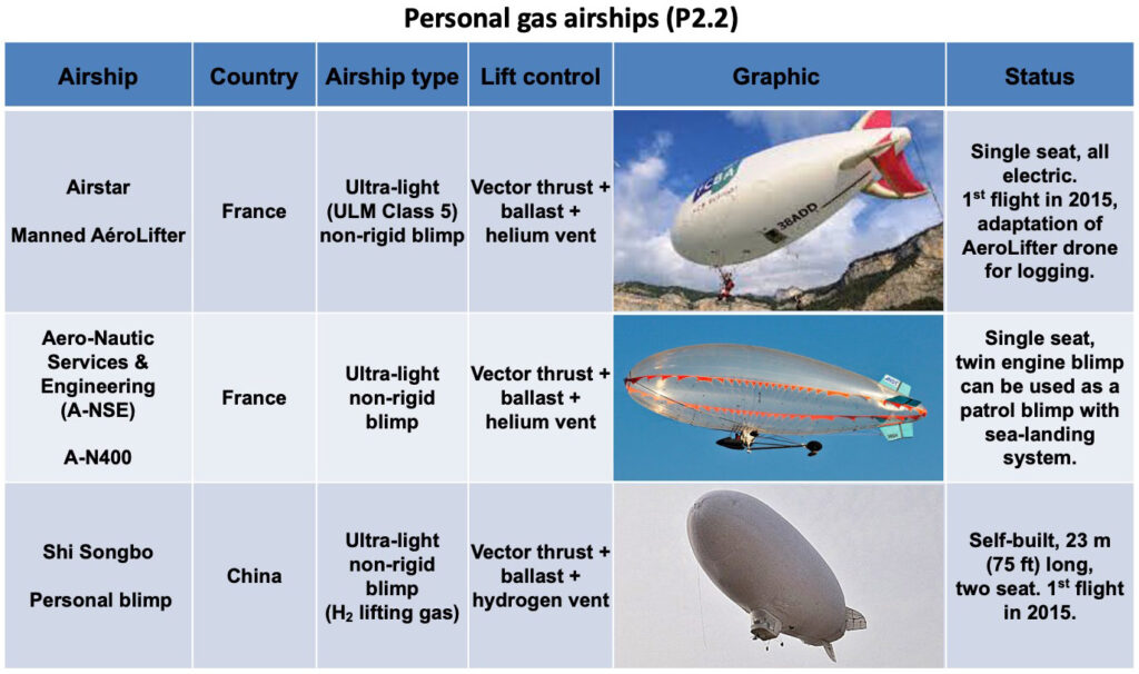
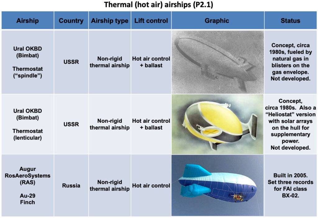
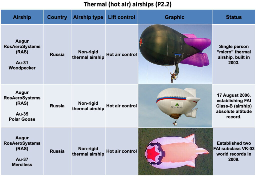
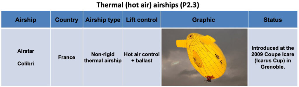
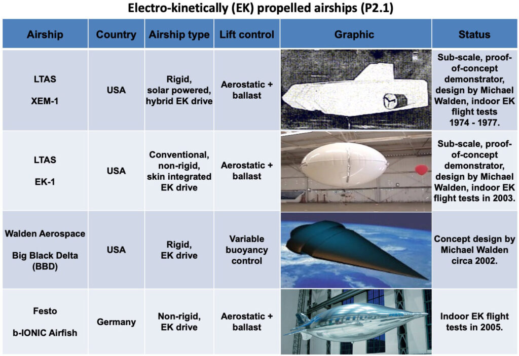
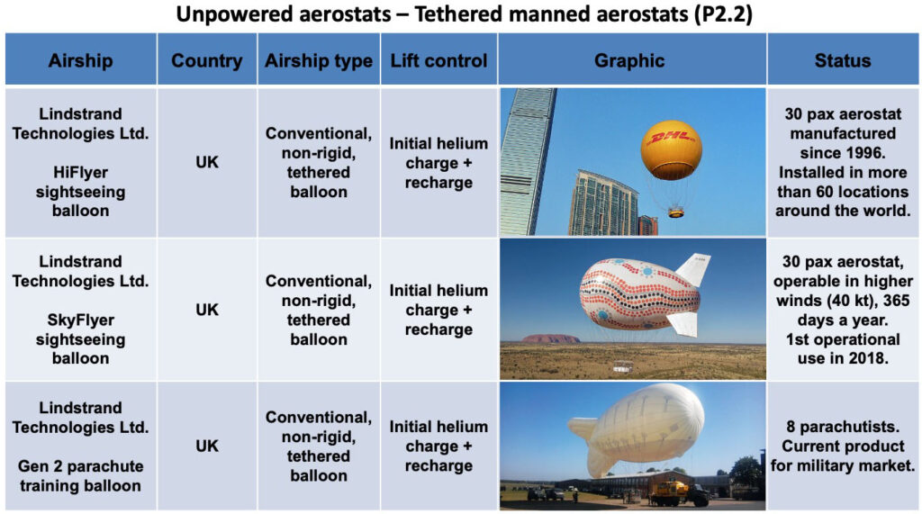
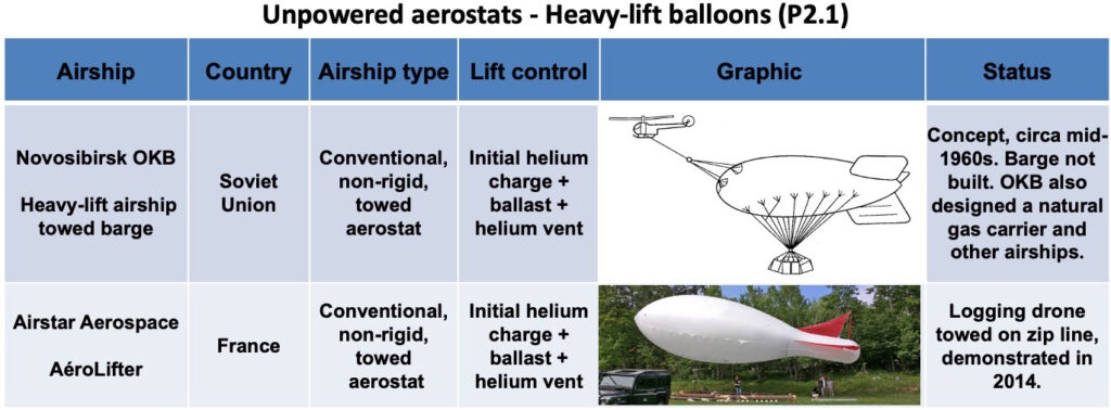
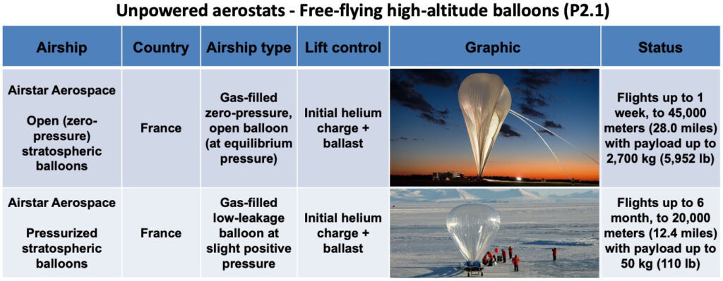
2. Graphic tables
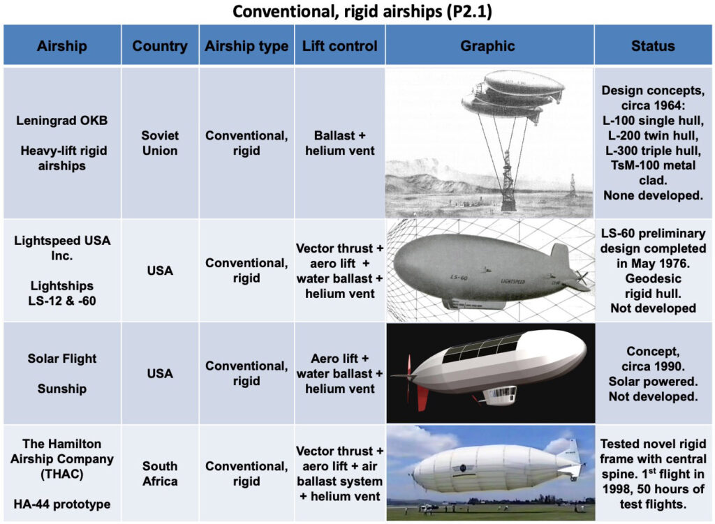
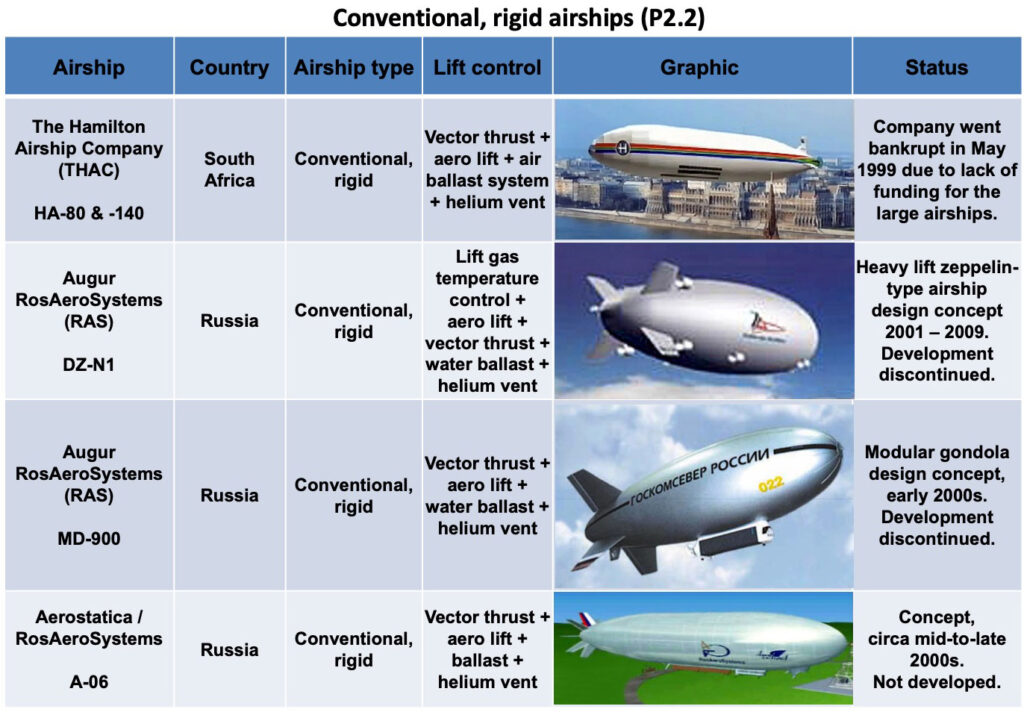
The airships reviewed in Modern Airships – Part 2 are summarized in the following set of graphic tables that are organized into the categories listed below:
Within each category, each page of the table is titled with the name of the airship type category and is numbered (P2.x), where P2 = Modern Airships – Part 2 and x = the sequential number of the page in that category. For example, “Conventional, rigid airships (P2.2)” is the page title for the second page in the “Conventional, rigid airships” category in Part 2. There also are conventional, rigid airships addressed in Modern Airships – Part 1. Within a category, the airships are listed in the graphic tables in approximate chronological order.
Links to the individual Part 2 articles on these airships are provided in Section 10. Some individual articles cover more than one particular airship. Have fun exploring!
3. Assessment of near-term LTA market prospects
Among the airships described in Part 2, the following advanced airship seems to be the best candidate for achieving type certification in the next five years:
Flying Whales (France): The LCA60T rigid cargo airship was significantly redesigned in 2021, which resulted in a considerable schedule delay. In March 2023, Flying Whales reported that they expected to complete construction and flight testing of the first production prototype in the 2024 – 2025 timeframe, followed by EASA certification and start of industrial production in 2026. The project appears to be well funded from diverse international sources in France, Canada, China and Morocco. Full-scale production facilities are planned in France, China and Canada and commercial airship operating infrastructure is being planned.
Hybrid Air Vehicles (UK): The Airlander 10 commercial passenger / cargo hybrid airship is being developed by HAV based on their experience with the Airlander 10 prototype, which flew from 2016 to 2017. In 2022, Valencia, Spain-based Air Nostrum, which operates regional flights, ordered 10 Airlander 10 aircraft, with delivery scheduled for 2026. Also in 2022, Highlands and Islands Airport (HIAL) sponsored a study for introducing the Airlander 10 in Scotland. In April 2023, the regional UK government of South Yorkshire concluded a financial agreement that is expected to lead to the Airlander 10 being manufactured in Doncaster, in the north of England. Things are moving in the right direction. In March 2023, HAV reported that manufacturing of the first production airship will start in 2023, followed by first flight in 2025 and service entry in 2027.
The following airship manufacturers in Part 2 have advanced designs and they seem to be ready to manufacture a first prototype if they can arrange funding:
Aerovehicles (USA / Argentina): They claim their AV-10 non-rigid, multi-mission blimp can carry a 10 metric ton payload and be type certified within existing regulations for blimps. This should provide a lower-risk route to market for an airship with an operational capability that does not exist today.
Atlas LTA Advanced Technology (Israel): After acquiring the Russian firm Augur RosAeroSystems in 2018, Atlas is continuing to develop the ATLANT variable buoyancy, fixed volume heavy lift airship. They also are developing a new family of non-rigid Atlas-6 and -11 blimps and unmanned variants. However, the development plans and schedules have not yet been made public.
BASI (Canada): The firm has a well-developed design in the MB-30T and a fixed-base operating infrastructure design that seems to be well suited for their primary market in the Arctic.
Euro Airship (France): The firm reports having production-ready plans for their rigid airship designs. In June 2023, Euro Airship announced plans to build and fly a large rigid airship known as Solar Airship One around the world in 2026.
Millennium Airship (USA & Canada): The firm has well developed designs for their SF20T and SF50T SkyFreighters, has identified its industrial team for manufacturing, and has a business arrangement with SkyFreighter Canada, Ltd., which would become a future operator of SkyFreighter airships in Canada. In addition, their development plan defines the work needed to build and certify a prototype and a larger production airship.
The promising airships in Part 2, listed above, will be competing in the worldwide airship market with candidates identified in Modern Airships – Part 1, which potentially could enter the market in the same time frame. Among the new airships described in Part 1, the following advanced airship seems to be the best candidates for achieving type certification in the next five years:
LTA Research and Exploration (USA): Their Pathfinder 1 rigid airship made its first free flight in October 2024 and has continued flight testing since then. The program appears to be well funded.
The following airship manufacturers in Part 1 have advanced designs and they seem to be ready to manufacture a first commercial prototype if they can arrange adequate funding:
AT2 Aerospace (USA): Their Z1 hybrid airship formerly was known as the Lockheed Martin LMH-1. In May 2023, Lockheed Martin exited the hybrid airship business without completing type certification and transitioned that business, including intellectual property and related assets, to the newly formed, commercial company AT2 Aerospace. In June, Straightline Aviation (a former LMH-1 customer) signed a Letter of Intent with AT2 Aerospace, signaling commercial support for the Z1 hybrid airship.
Aeros (USA): It seems that Aeros has been ready for more than a decade to begin type certification and manufacture a prototype of their Aeroscraft ML866 / Aeroscraft Gen 2 variable buoyancy / fixed volume airship. The firm has reported successful subsystem tests.
For decades, there have been many ambitious projects that intended to operate an airship as a pseudo-satellite, carrying a heavy payload while maintaining a geo-stationary position in the stratosphere on a long-duration mission (days, weeks, to a year or more). None were successful. This led NASA in 2014 to plan the 20-20-20 airship challenge: 20 km altitude, 20 hour flight, 20 kg payload. The challenge never occurred, but it highlighted the difficulty of developing an airship as a persistent pseudo-satellite. The most promising new stratospheric airship manufacturers identified in Part 2 are:
Sceye Inc. (USA): This small firm has built a headquarters and manufacturing facility in New Mexico. Since 2017, it has been developing a mid-size, multi-mission stratospheric airship aimed at demonstrating the ability to deliver communications services to users living in remote regions. A sub-scale vehicle first flew in 2017. Short-duration flights of a prototype stratospheric airship have been conducted since 2021. In 2024, Sceye demonstrated controlled relocation and the ability to remain positioned over a designated area for more than 24 hours. In 2025, SoftBank Corp. announced that it had invested in Sceye with the goal of launching pre-commercial HAPS services in Japan in 2026.
Thales Alenia Space (France): The firm is developing the multi-mission Stratobus. Their latest round of funding from France’s defense procurement agency called for a full-scale, autonomous Stratobus demonstrator airship to fly by the end of 2023, five years later than another demonstrator that was ordered in the original 2016 Stratobus contract, but not built. Thales Alenia Space missed the end of 2023 target and, by early 2026, only a sub-scale “Babybus” ground test article has been completed. An updated schedule for delivering the first Stratobus vehicle has not been announced.
China remains an outlier after the 2015 flight of the Yuanmeng stratospheric airship developed by Beijing Aerospace Technology Co. & BeiHang. The current status of the Chinese stratospheric airship development program is not described in public documents.
Among the many smaller airships identified in Part 2, the following manufacturers could have their airships flying by the mid 2020s if adequate funding becomes available.
Dirisolar (France): The firm has a well-developed design for their five passenger DS 1500, which is intended initially for local air tourism, but can be configured for other missions. When funding becomes available, it seems that they’re ready to go.
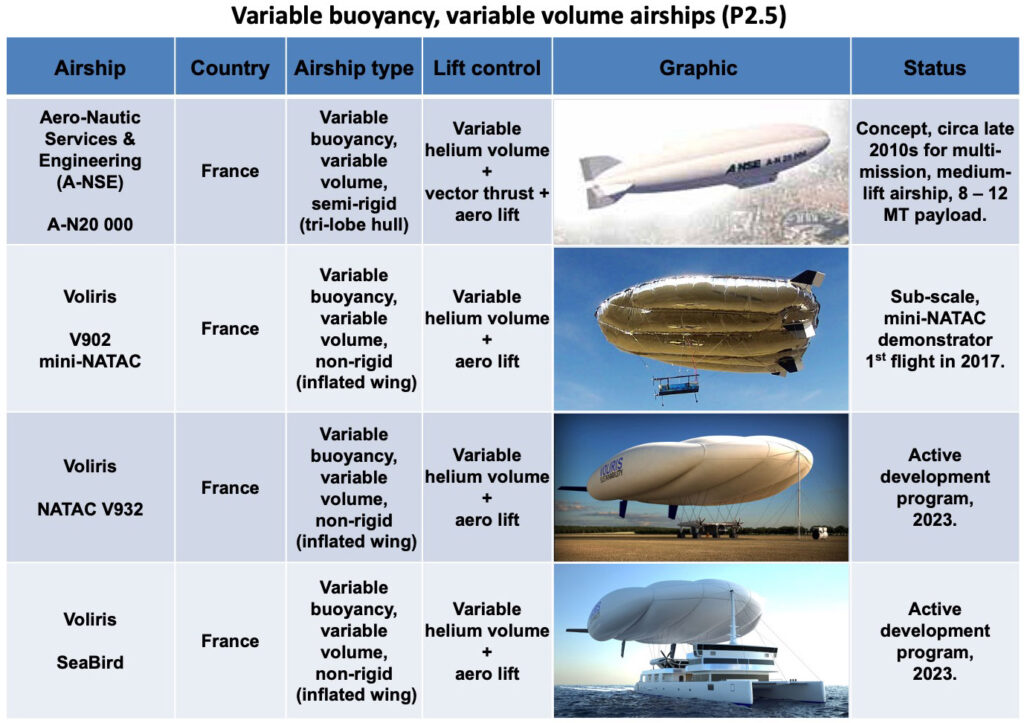
A-NSE (France): The firm offers a range of aerostat and small airships, several with a novel tri-lobe, variable volume hull design. Such aerostats are operational now, and a manned tri-lobe airship could be flying later in the 2020s.
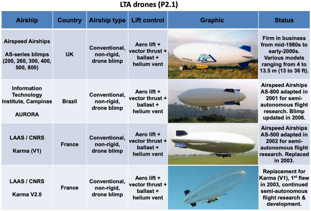
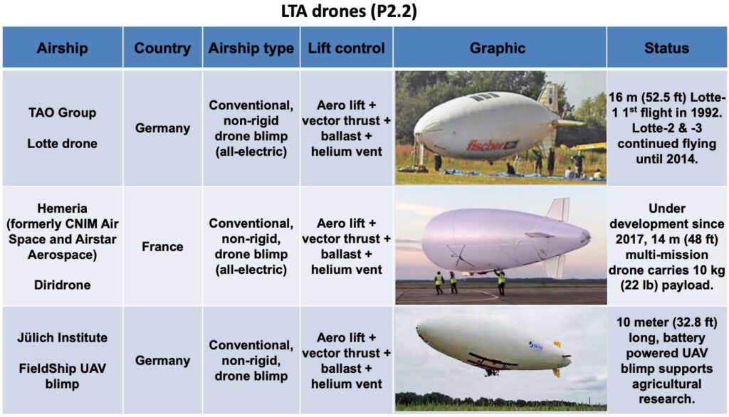
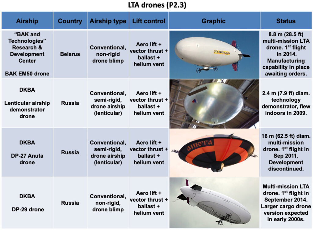
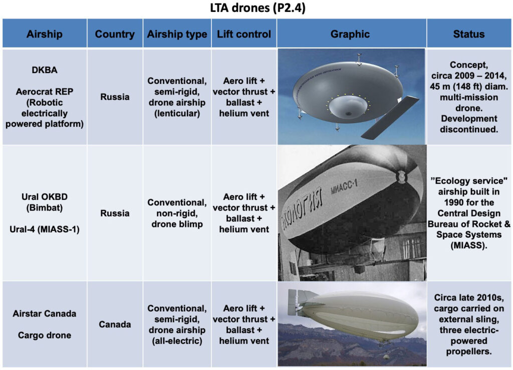
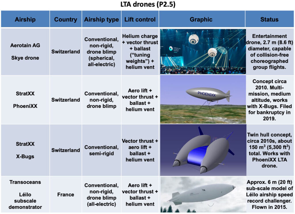
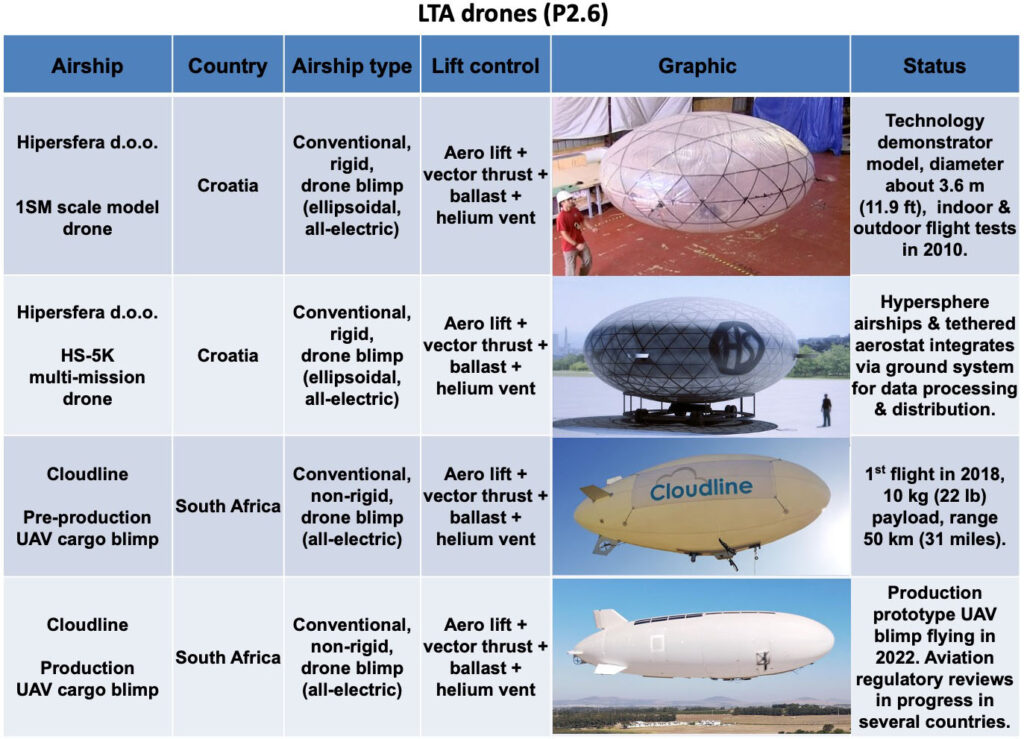
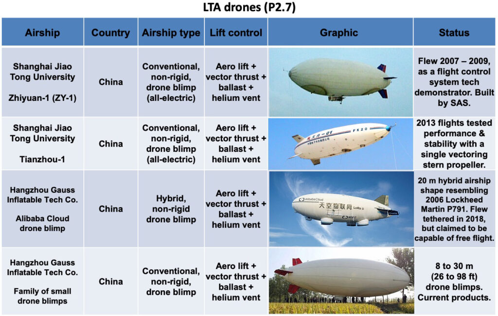
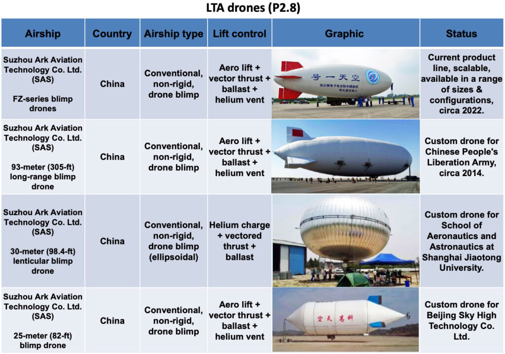
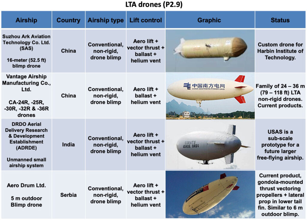
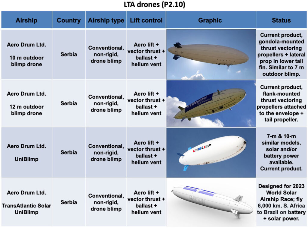
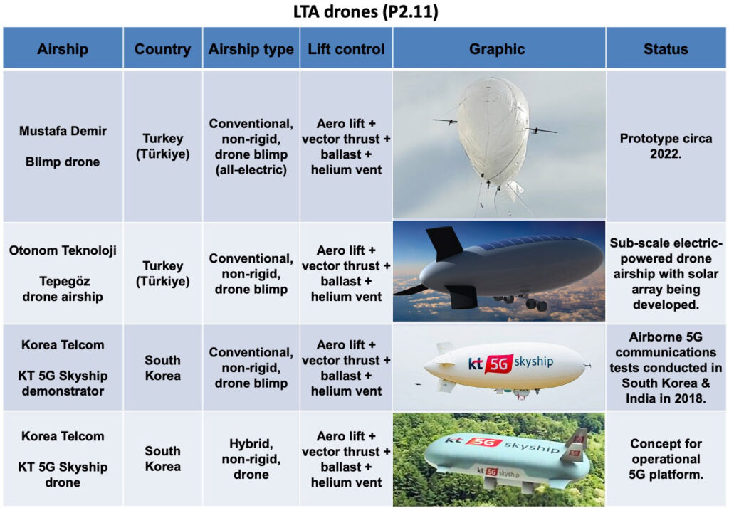
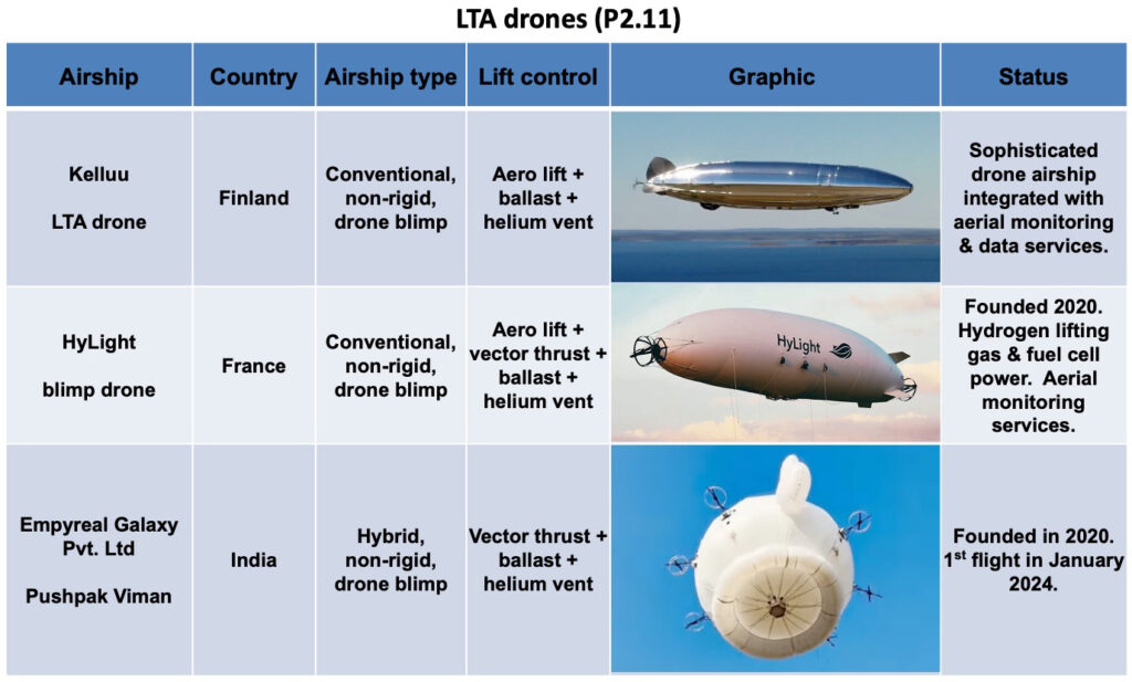
There has been a proliferation of small LTA drone blimps and other small LTA drone vehicles. Some were developed initially for military surveillance applications, but all are configurable and could be deployed in a range of applications. Some enterprising LTA drone developers also are developing value-adding applications and are offering information services, rather than simply selling a drone to be operated by a customer.
The 2020s will be an exciting time for the airship industry. We’ll finally get to see if the availability of several different heavy-lift airships with commercial type certificates will be enough to open a new era in airship transportation. Aviation regulatory agencies need to help reduce investment risk by reducing regulatory uncertainty and putting in place an adequate regulatory framework for the wide variety of advanced airships being developed. Customers with business cases for airship applications need to step up, place firm orders, and then begin the pioneering task of employing their airships and building a worldwide airship transportation network with associated ground infrastructure. This will require consistent investment over the next decade or more before a basic worldwide airship transportation network is in place to support the significant use of commercial airships in cargo and passenger transportation and other applications. Perhaps then we’ll start seeing the benefits of airships as a lower environmental impact mode of transportation and a realistic alternative to fixed-wing aircraft, seaborne cargo vessels and heavy, long-haul trucks.
4. Links to the individual articles
The following links will take you to the individual articles that address all of the airships identified in the preceding graphic table.
Note that a few of these articles address more than one airship design from the same manufacturer / designer and they may be in different categories (i.e., Augur RosAeroSystems, Atlas LTA Advanced Technology). These designs are listed separately in the above graphic tables and the following index. The links listed below will take you to the same article.
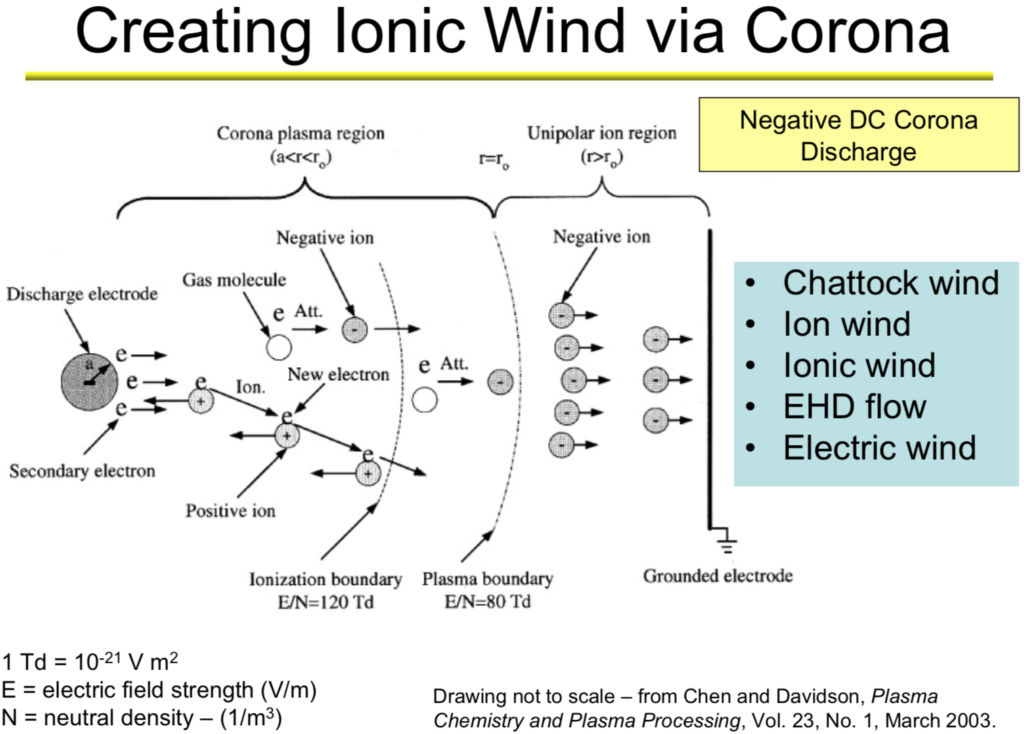
When charged molecules in the air are subjected to an electric field, they are accelerated. When these charged molecules collide with neutral ones, they transfer part of their momentum, leading to air movement known as an “ionic wind.” This basic process is shown in the following diagram, which depicts a strong electric field between a discharge electrode (left) and a ground electrode (right), and the motion of negative ions toward the ground electrode where they are collected. The neutral molecules pass through the ground electrode and generate the thrust called the ionic wind.
This post summarizes work that has been done to develop ionic wind propulsion systems for aircraft. The particular projects summarized are the following:
Major Alexander de Seversky’s Ionocraft vertical lifter (1964)
Michael Walden / LTAS lighter-than-air XEM-1 (1977)
Michael Walden / LTAS lighter-than-air EK-1 (2003)
The Festo b-IONIC Airfish airship (2005)
NASA ionic wind study (2009)
The MIT electroaerodynamic (EAD) heaver-than-air, fixed wing aircraft (2018)
In addition, we’ll take a look at recent ionic propulsion work being done by Electrofluidsystems Ltd., Electron Air LLC and the University of Florida’s Applied Physics Research Group.
2. Scale model of ion-propelled Ionocraft vertical takeoff lifter flew in 1964
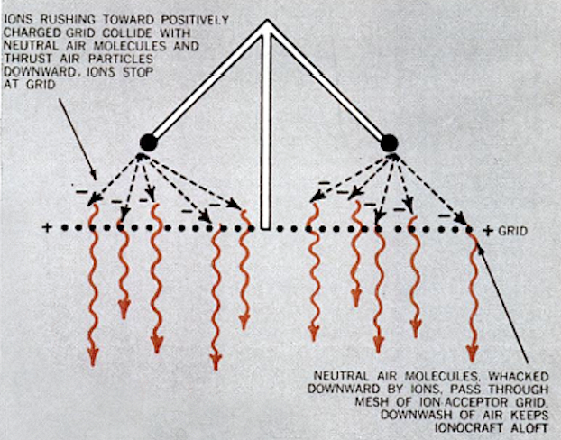
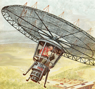
Major Alexander de Seversky developed the design concept for a novel aircraft concept called the “Ionocraft,” which was capable of hovering or moving in any direction at high altitudes by means of ionic discharge. His design for the Ionocraft is described in US Patent 3,130,945, “Ionocraft,” dated 28 April 1964. You can read this patent here: https://patents.google.com/patent/US3130945A/en
The operating principle of de Seversky’s Ionocraft propulsion system is depicted in the following graphic.
Ion propulsion scheme implemented in the de Seversky Ionocraft. Source: Popular Mechanics, August 1964
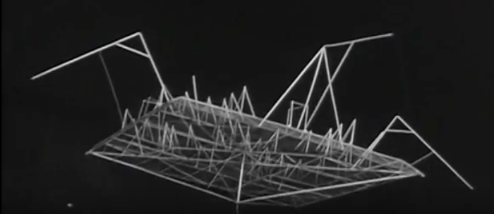
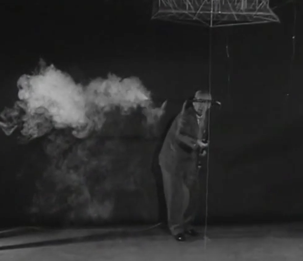
In 1964, de Seversky built a two-ounce (57 gram) Ionocraft scale model and demonstrated its ability to fly while powered from an external 90 watt power conversion system (30,000 volts at 3 mA), significantly higher that conventional aircraft and helicopters. This translated into a power-to-weight ratio of about 0.96 hp/pound. You can watch a short 1964 video of a scale model Ionocraft test flight here:
Screenshot showing Ionocraft scale model in flightScreenshot showing ionic wind downdraft under an Ionocraft scale model in flight
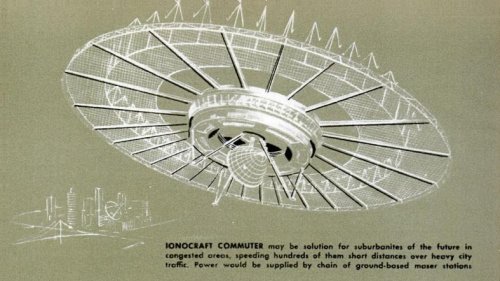
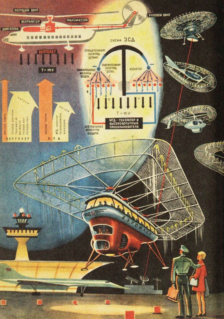
Alexander de Seversky’s one-man Ionocraft concept. Source: Popular Mechanics Archive, August 1964Alexander de Seversky’s Ionocraft commuter concept. Source: Popular Mechanics Archive, August 19641969 Soviet concepts for passenger carrying Ionocraft. Technology for Youth magazine, 1969, Issue 7.
In the 1960s, engineers found that Ionocraft technology did not scale up well and they were unable to build a vehicle that could generate enough lift to carry the equipment needed to produce the electricity needed to drive it.
3. The first free-flying, ion-propelled, lighter-than-air craft flew in 1977: Michael Walden / LTAS XEM-1
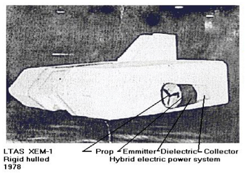
The subscale XEM-1 proof-of-concept demonstrator was designed by Michael Walden and built in 1974 by his firm, Lighter Than Air Solar (LTAS) in Nevada. After leaving LTAS in 2005, Michael Walden founded Walden Aerospace where he is the President and CTO, building on the creative legacy of his work with the former LTAS firms. The Walden Aerospace website is here: http://walden-aerospace.com/HOME.html
The basic configuration of this small airship is shown in the following photo. The MK-1 ionic airflow (IAF) hybrid EK drives are mounted on the sides of the airship’s rigid hull.
Source: Walden Aerospace.
Basic configuration of the MK-1 ionic airflow (IAF) hybrid EK drive. Source: Walden Aerospace.
XEM-1 originally was tethered by cable to an external control unit and later was modified for wireless remote control operation. In this latter configuration, XEM-1 demonstrated the use of a hybrid EK propulsion system in a self-powered, free-flying vehicle.
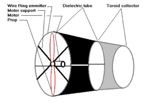
Walden described the MK-1 IAF EK drive as follows: “The duct included a 10 inch ‘bent tip’ 3-bladed prop running on an electric motor to create higher pressures through the duct, making it a ‘modified pressure lifter’…. The duct also had a circular wire emitter, a dielectric separator and a toroidal collector making it a ‘toroid lifter’.”
The later MK-2 and MK-3 IAF EK drives had a similar duct configuration. In all of these EK drives, the flow of ions from emitter to collector imparts momentum to neutral air molecules, creating usable thrust for propulsion. You’ll find more information on the MK-1 IAF EK drive and later versions on the Walden Aerospace website here: http://walden-aerospace.com/Waldens_Patents_files/Walden%20Aerospace%20Advanced%20Technologies%2011092013-2.pdf
The XEM-1 was demonstrated to the Department of Defense (DoD) and Department of Energy (DOE) in 1977 at Nellis Air Force Base in Nevada. Walden reported: “We flew the first fully solar powered rigid airship in 1974, followed by a US Department of Defense and Department of Energy flight demonstration in August 1977”…. “ DoD was interested in this work to the extent that some of it is still classified despite requests for the information to become freely available.”
Walden credits the XEM-1 with being the first fully self-contained air vehicle to fly with a hybrid ionic airflow electro-kinetic propulsion system. This small airship also demonstrated the feasibility of a rigid, composite, monocoque aeroshell, which became a common feature on many later Walden / LTAS airships.
4. The second free-flying, ion-propelled, lighter-than-air craft flew in 2003: Michael Walden / LTAS EK-1
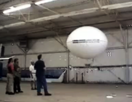
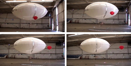
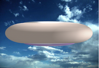
Michael Walden designed the next-generation EK-1, which was a remotely controlled, self-powered, subscale model of a lenticular airship with a skin-integrated EK drive that was part of the outer surface of the hull. The drive was electronically steered to provide propulsion in any direction with no external aerodynamic surfaces and no moving parts.
EK-1 aloft in the hanger. Source: LTAS / Walden Aerospace
EK-1 with a skin-integrated propulsion system moving during hanger test flight in 2003.Source: LTAS / Walden Aerospace
In June 2003, LTAS rented a hangar at the Boulder City, NV airport to build and fly the EK-1. Testing the EK-1 was concluded in early August 2003 after demonstrating the technology to National Institute for Discovery Science (NIDS) board members.
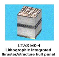
Based on the EK-1 design, a full-scale EK airship would have a rigid, aeroshell comprised largely of LTAS MK-4 lithographic integrated thruster / structure hull panels. As with other contemporary Walden / LTAS airship designs, the MK-4 panel airship likely would have implemented density controlled buoyancy (DCB) active aerostatic lift control and would have had a thin film solar array on the top of the aeroshell.
Artist’s concept of a MK-4 panel airship. Source: Walden Aerospace
5. The third free-flying, ion-propelled, lighter-than-air craft flew in 2005: the Festo b-IONIC Airfish
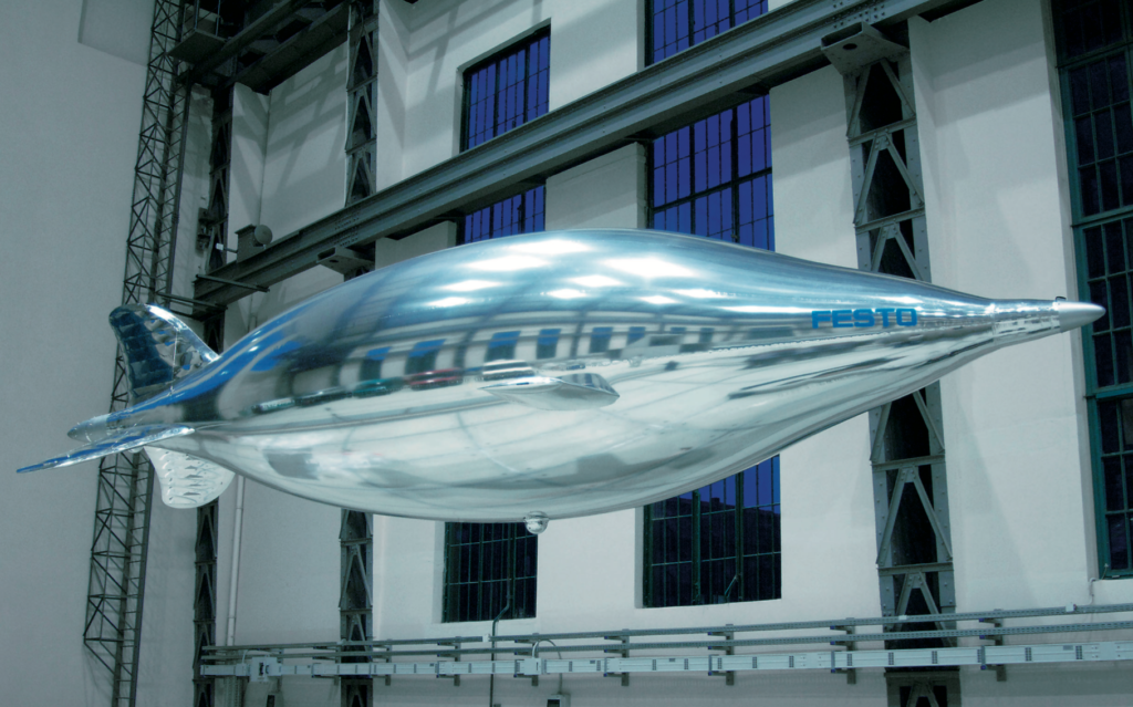
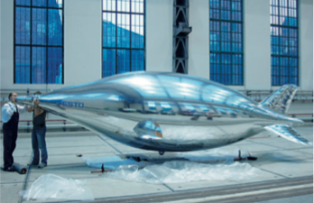
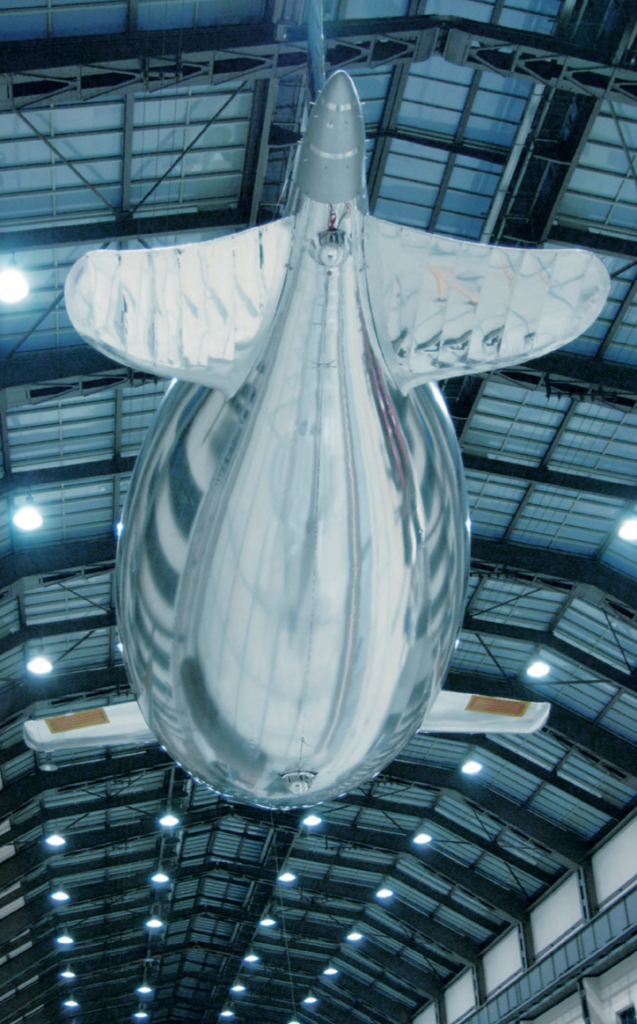
The Festo b-IONIC Airfish airship was developed at the Technical University of Berlinwith guidance of the firm Festo AG & Co. KG. This small, non-rigid airship is notable because, in 2005, it became the first aircraft to fly with a solid state propulsion system. The neutrally-buoyant Airfish only flew indoors, in a controlled environment, at a very slow speed, but it flew.
Airfish. Source: Festo AG & Co. KG
Some of the technical characteristics of the Airfish are listed below:
Length: 7.5 meters (24.6 ft)
Span: 3.0 meters (9.8 ft)
Shell diameter: 1.83 meters (6 ft)
Helium volume: 9.0 m3(318 ft3)
Total weight: 9.04 kg (19.9 lb)
Power source in tail: 12 x 1,500 mAh lithium-ion polymer cells (18 Ah total)
Power source per wing (two wings): 9 x 3,200 mAh lithium-ion polymer cells (28.8 Ah total)
High voltage: 20,000 to 30,000 volts
Buoyancy: 9.0 – 9.3 kg (19.8 – 20.5 lb)
Total thrust: 8 – 10 grams (0.018 – 0.022 pounds)
Maximum velocity: 0.7 meters/sec (2.5 kph; 1.6 mph)
The b-IONIC Airfish employed two solid state propulsion systems, an electrostatic ionic jet and a plasma ray, which Festo describes as follows:
Electrostatic ionic jet: “At the tail end Airfish uses the classic principle of an electrostatic ionic jet propulsion engine. High-voltage DC-fields (20-30 kV) along thin copper wires tear electrons away from air molecules. The positive ions thus created are then accelerated towards the negatively charged counter electrodes (ring-shaped aluminum foils) at high speeds (300-400 m/s), pulling along additional neutral air molecules. This creates an effective ion stream with speeds of up to 10 m/s.”
Plasma-ray: “The side wings of Airfish are equipped with a new bionic plasma-ray propulsion system, which mimics the wing based stroke principle used by birds, such as penguins, without actually applying movable mechanical parts. As is the case with the natural role model, the plasma-ray system accelerates air in a wavelike pattern while it is moving across the wings.”
Airfish. Source: Festo AG & Co. KG
Airfish. Source: Festo AG & Co
The Festo b-IONIC Airfish demonstrated that a solid state propulsion system was possible. The tests also demonstrated that the solid state propulsion systems also reduced drag, raising the intriguing possibility that it may be possible to significantly reduce drag if an entire vessel could be enclosed in a ionized plasma bubble.You’ll find more information on the Festo b-IONIC Airfish, its solid state propulsion system and implications for drag reduction in the the Festo brochure here: https://www.festo.com/net/SupportPortal/Files/344798/b_IONIC_Airfish_en.pdf
You can watch a 2005 short video on the Festo b-IONIC Airfish flight here:
6. NASA ionic wind study – 2009
A corona discharge device generates an ionic wind, and thrust, when a high voltage corona discharge is struck between sharply pointed electrodes and larger radius ground electrodes.
In 2009, National Aeronautics & Space Administration (NASA) researchers Jack Wilson, Hugh Perkins and William Thompson conducted a study to examine whether the thrust of corona discharge systems could be scaled to values of interest for aircraft propulsion. Their results are reported in report NASA/TM-2009-215822, which you’ll find at the following link: https://ntrs.nasa.gov/archive/nasa/casi.ntrs.nasa.gov/20100000021.pdf
Key points of the study included:
Different types of high voltage electrodes were tried, including wires, knife-edges, and arrays of pins. A pin array was found to be optimum.
Parametric experiments, and theory, showed that the thrust per unit power could be raised from early values of 5 N/kW to values approaching 50 N/kW, but only by lowering the thrust produced, and raising the voltage applied.
In addition to using DC voltage, pulsed excitation, with and without a DC bias, was examined. The results were inconclusive as to whether this was advantageous.
It was concluded that the use of a corona discharge for aircraft propulsion did not seem very practical.”
7. The first heavier-than-air, fixed-wing, ion-propelled aircraft flew in 2018
On 21 November 2018, MIT researchers reported successfully flying the world’s first heavier-than-air, fixed-wing, ion-propelled (electroaerodynamic, EAD) aircraft. You can read the paper by Haofeng Xu, et al., “Flight of an aeroplane with solid-state propulsion,” on the Nature website here: https://www.nature.com/articles/s41586-018-0707-9
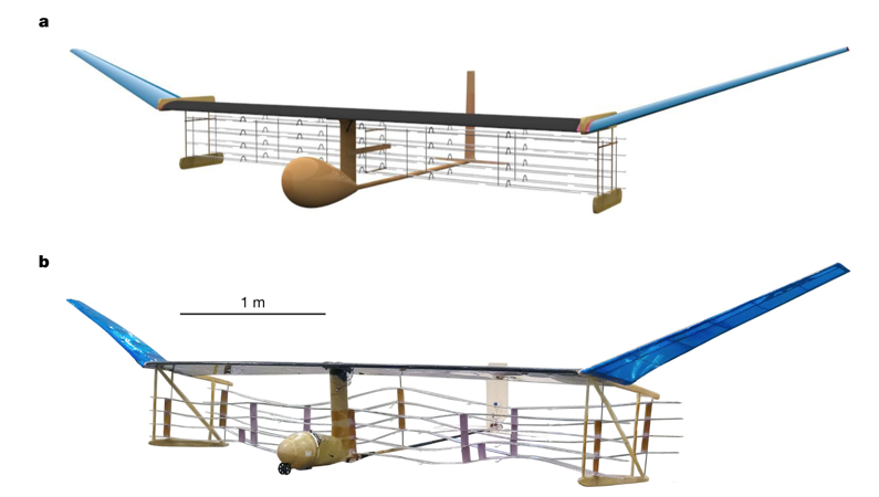
The design of the MIT EAD aircraft is shown below:
a, Computer-generated rendering of the EAD airplane. b, Photograph of actual EAD airplane (after multiple flight trials).
Some of the technical characteristics of this MIT aircraft are listed below:
Wingspan: 4.9 meters (16 ft)
Total weight: 2.45 kg (5.4 lb)
Power source: powered by 54 x 3.7 volt 150 mAh lithium-ion polymer cells (8.1 Ah total)
Maximum velocity: 4.8 meters/sec (17.3 kph; 10.7 mph)
In their paper, the MIT researchers reported:
“We performed ten flights with the full-scale experimental aircraft at the MIT Johnson Indoor Track…. Owing to the limited length of the indoor space (60 m), we used a bungeed launch system to accelerate the aircraft from stationary to a steady flight velocity of 5 meters/sec within 5 meters, and performed free flight in the remaining 55 meters of flight space. We also performed ten unpowered glides with the thrusters turned off, in which the airplane flew for less than 10 meters. We used cameras and a computer vision algorithm to track the aircraft position and determine the flight trajectory.”
“All flights gained height over the 8–9 second segment of steady flight, which covered a distance of 40–45 meters…. The average physical height gain of all flights was 0.47 meters…. However, for some of the flights, the aircraft velocity decreased during the flight. An adjustment for this loss of kinetic energy…. results in an energy equivalent height gain, which is the height gain that would have been achieved had the velocity remained constant. This was positive for seven of the ten flights, showing that better than steady-level flight had been achieved in those cases.”
“In this proof of concept for this method of propulsion, the realized thrust-to-power ratio was 5 N/kW1, which is of the order of conventional airplane propulsion methods such as the jet engine.” Overall efficiency was estimated to be 2.56%.
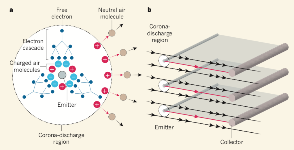
The propulsion principles of the MIT EAD aircraft are explained in relation to the following diagram in the November 2018 article by Franck Plouraboué, “Flying With Ionic Wind,” which you can read on the Nature website at the following link: https://www.nature.com/articles/d41586-018-07411-z
The following diagram and explanatory text are reproduced from that article.
In Figure a, above: …an electric field (not shown) is applied to the region surrounding a fine wire called the emitter (shown in cross-section). The field induces electron cascades, whereby free electrons collide with air molecules (not shown in the cascades) and consequently free up more electrons. This process produces charged air molecules in the vicinity of the emitter — a corona discharge. Depending on the electric field, negatively or positively charged molecules drift away (red arrows) from the emitter. These molecules collide with neutral air molecules, generating an ionic wind (black arrows).
In Figure b, above: The aircraft uses a series of emitters and devices called collectors, the longitudinal directions of which are perpendicular to the ionic wind. The flow of charged air molecules occurs mainly along the directions (red arrows) joining emitters and collectors. Consequently, the ionic wind is accelerated (black arrows) predominantly in these regions.
You can view a short video of the MIT EAD aircraft test flights here:
8. The future of ionic propulsion for aerospace applications.
If it can be successfully developed to much larger scales, ionic propulsion offers the potential for aircraft to fly in the atmosphere on a variety of practical missions using only ionized air for propulsion. Using other ionized fluid media, ionic propulsion could develop into a means to fly directly from the surface of the earth into the vacuum of space and then operate in that environment. The following organizations have been developing such systems.
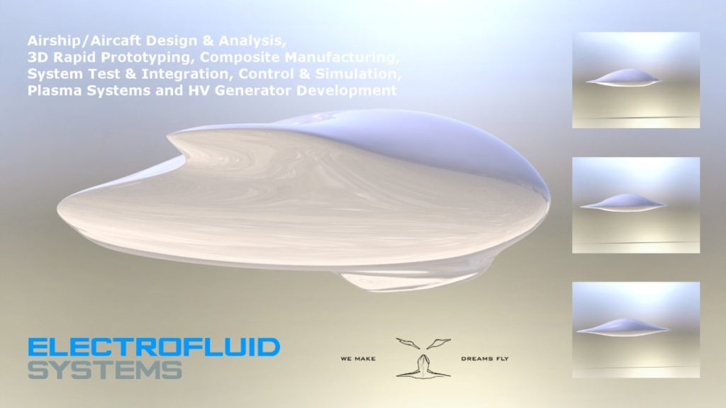
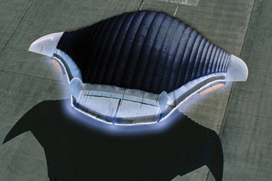
Electrofluidsystems Ltd.
In 2006, the Technical University of Berlin’s Airfish project manager, Berkant Göksel, founded the firm Electrofluidsystems Ltd., which in 2012 was rebranded as IB Göksel Electrofluidsystems. This firm presently is developing a new third generation of plasma-driven airships with highly reduced ozone and nitrogen oxide (NOx) emissions, magneto-plasma actuators for plasma flow control, and the company’s own blended wing type flying wing products. You’ll find their website here: https://www.electrofluidsystems.com
Source: Electrofluidsystems TU BerlinAdvanced plasma-driven aircraft concept. Source: Electrofluidsystems TU Berlin
MIT researchers are developing designs for high-performance aircraft using ionic propulsion. Theoretically, efficiency improves with speed, with an efficiency of 50% possible at a speed of about 1,000 kph (621 mph). You can watch a short video on MIT work to develop a Star Trek-like ion drive aircraft here:
Electron Air LLC
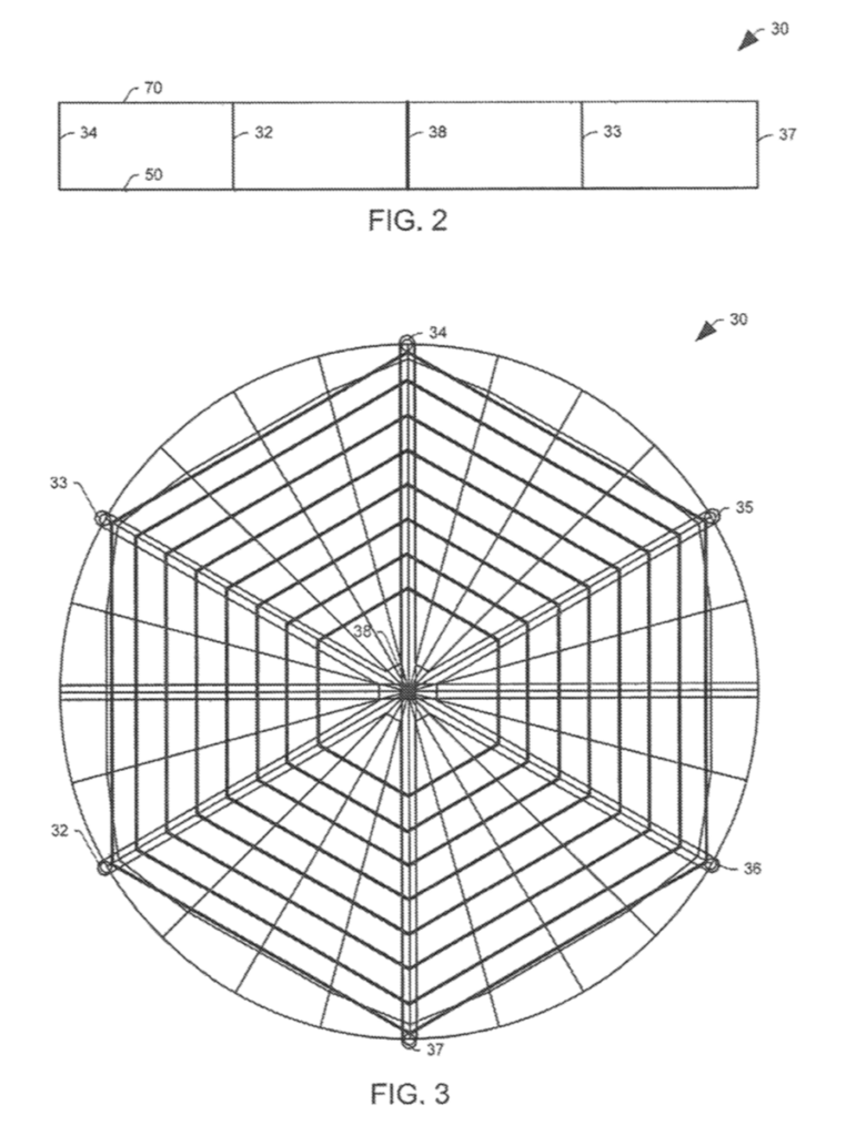
Another firm active in the field of ionic propulsion is Electron Air LLC (https://electronairllc.org), which, on 6 November 2018, was granted patent US10119527B2 for their design for a self-contained ion powered craft. Their grid shaped craft is described as follows:
“The aircraft assembly includes a collector assembly, an emitter assembly, and a control circuit operatively connected to at least the emitter and collector assemblies and comprising a power supply configured to provide voltage to the emitter and collector assemblies. The assembly is configured, such that, when the voltage is provided from an on board power supply, the aircraft provides sufficient thrust to lift each of the collector assembly, the emitter assembly, and the entire power supply against gravity.”
The device, as shown in patent Figure 3, consists of a two-layer grid structure with a collector assembly (50), an emitter assembly (70) and peripheral supports (33 to 37).
This patent cites Alexander de Seversky’s Patent 3130945, “Ionocraft.”
You can watch a short (1:22 minute) video of an outdoor tethered test flight of a remotely controlled, self-contained, ion powered, heavier-than-air craft with onboard power at the following link: https://www.youtube.com/watch?v=aX21HCHlgKo
University of Florida, Applied Physics Research Group
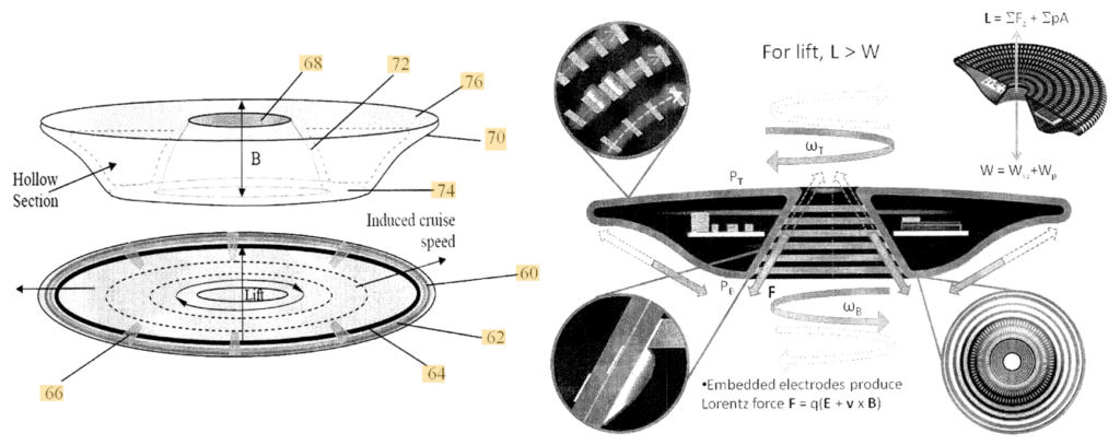
In the early 2000s, a Wingless Electromagnetic Air Vehicle (WEAV) was invented by Dr. Subrata Roy, a plasma physicist and aerospace engineering professor at the University of Florida. WEAV is described as a heavier-than-air flight system that can self-lift, hover, and fly using plasma propulsion with no moving components. The laboratory-scale device is six inch (15.2 cm) in diameter. The basic configuration of the disc-shaped craft is shown in patent 8960595B2 Figure 1.
This research project has been supported by the US Air Force Office of Scientific Research. You’ll find details on WEAV technology in the University of Florida’s 2011 final report at the following (very slow loading) link:https://apps.dtic.mil/dtic/tr/fulltext/u2/a564120.pdf
In this report, the authors describe the technology: “This revolutionary concept is based on the use of an electro-(or magneto) hydrodynamic (EHD/MHD) thrust generation surface that is coated with multiple layers of dielectric polymers with exposed and/or embedded electrodes for propulsion and dynamic control. This technology has the unique capability of imparting an accurate amount of thrust into the surrounding fluid enabling the vehicle to move and react. Thrust is instantaneously and accurately controlled by the applied power, its waveform, duty cycle, phase lag and other electrical parameters. Once the applied power is removed the thrust vanishes.”
The following patents related to WEAV technology have been filed and assigned to the University of Florida Research Foundation Inc.:
M. Robinson, “Movement of Air in the Electric Wind of the Corona Discharge:, Technical Paper TP60-2, Research-Cottrell, Inc., Bound Brook, NJ, 8 June 1960; https://apps.dtic.mil/dtic/tr/fulltext/u2/262830.pdf
P. Zheng, et al., “A Comprehensive Review of Atmospheric-Breathing Electric Propulsion Systems,” International Journal of Aerospace Engineering, Article ID 8811847, 7 October 2020; https://www.hindawi.com/journals/ijae/2020/8811847/
Nicolas Monrolin, Franck Plouraboué, Olivier Praud.“Electrohydrodynamic Thrust for In-Atmosphere Propulsion,” AIAA Journal, American Institute of Aeronautics and Astronautics, 2017, vol. 55 (n° 12), pp. 4296-4305. 10.2514/1.J055928 . hal-01660600; https://hal.archives-ouvertes.fr/hal-01660600/document
Daniel Drew, “The Ionocraft: Flying Microrobots With No Moving Parts,” Technical Report No. UCB/EECS-2018-164, Electrical Engineering and Computer Sciences, University of California at Berkeley, 10 December 2018; https://www2.eecs.berkeley.edu/Pubs/TechRpts/2018/EECS-2018-164.pdf
WEAV
Subrata Roy, et al., “Demonstration of a Wingless Electromagnetic Air Vehicle,” Final Report AFRL-OSR-VA-TR-2012-0922, University of Florida, Applied Physics Research Group: https://apps.dtic.mil/dtic/tr/fulltext/u2/a564120.pdf