Peter Lobner
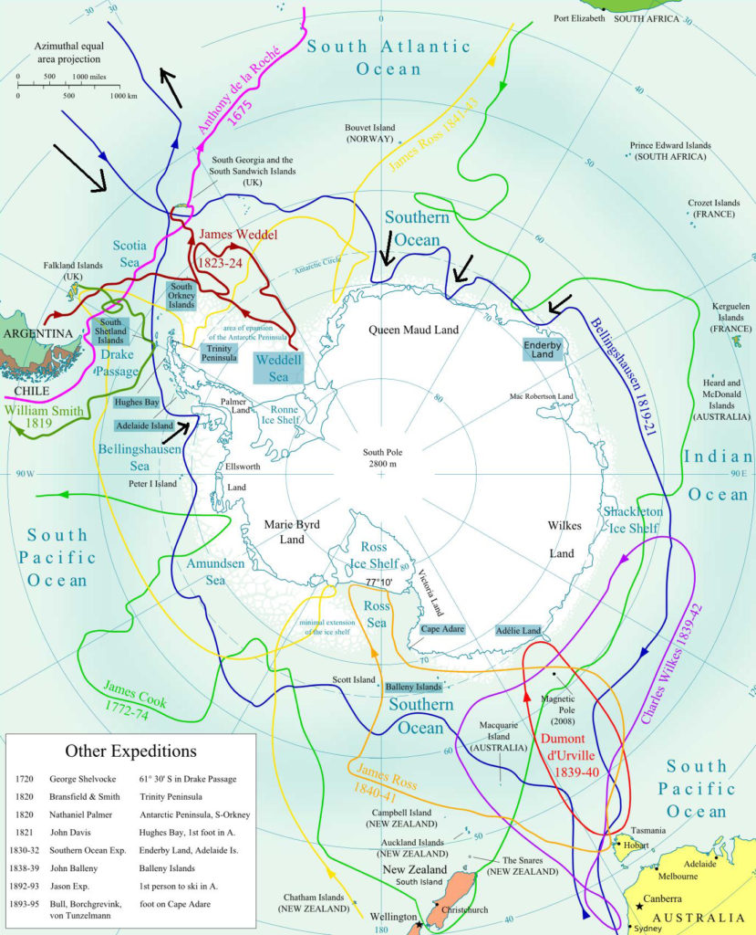
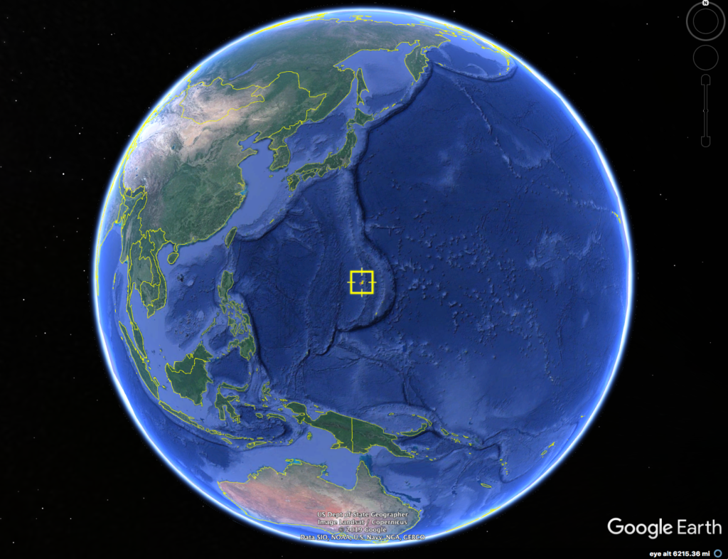
The Challenger Deep, in the Mariana Trench in the middle of western Pacific Ocean, is the deepest known area in the world’s oceans. Its location, as shown in the following map, is 322 km (200 miles) southwest of Guam and 200 km (124 miles) off the coast of the Mariana Islands.
Since the first visit to the bottom of the Challenger Deep 60 years ago, on 23 January 1960, there have been only five other visits to that very remote and inhospitable location. In this post, we’ll take a look at the deep-submergence vehicles (DSVs) and the people who made these visits.
The following topographical map, created in 2019 by the Five Deeps Expedition, shows that the Challenger Deep is comprised of three deeper “pools.” The dive locations of the manned expeditions into the Challenger Deep are shown on this map.
- 1960: Navy Lieutenant Don Walsh and Swiss engineer Jacques Piccard, in the bathyscaphe Trieste, made the first manned descent into the Challenger Deep and reached the bottom at 10,916 meters (35,814 ft) in the “Western Pool.”
- 2012: Canadian filmmaker and National Geographic Explorer-in-Residence James Cameron, in the DSV Deepsea Challenger, reached the bottom at 10,908 meters (35,787 ft) the “Eastern Pool.”
- 2019: Businessman, explorer and retired naval officer Victor Vescovo, in the DSV Limiting Factor, made two dives in the “Eastern Pool” and reached a maximum depth of 10,925 meters (35,843 feet).
- 2019: Triton Submarine president, Patrick Lahey, in the DSV Limiting Factor, made two dives to the bottom, one in the Eastern Pool and one in the Central Pool.
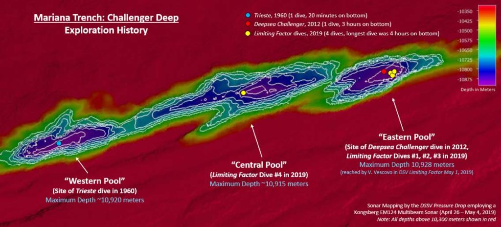
Source: Five Deeps Expedition
What is there to see on the way down to the bottom?
The oceans can be divided into vertical zones based on water depth. This basic concept is shown in the following diagram.
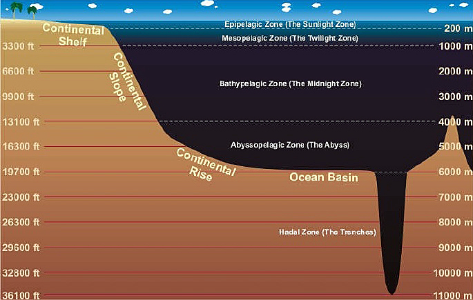
The five vertical zones in the above diagram have the following general characteristics:
- The Sunlight Zone: This is the shallow (upper 150 meters), sunlit upper layer of the ocean, extending above the continental shelf. Phytoplankton can photosynthesize in this zone.
- The Twilight Zone: This is the medium-depth ocean where sunlight is still able to penetrate to a modest depth (a few hundred meters). There is enough light to see, but not enough for photosynthesis. This zone is bounded by the edges of the continental shelf and islands in the deep ocean.
- The Midnight Zone: This is the deep ocean, which is bounded by the continental slope and the seamounts and islands rising above the ocean floor. No sunlight is able to reach this deep. There is no photosynthesis in this zone.
- The Abyssal Zone: This zone includes the deep ocean plains and the deep cusp of the continental rise. The temperature here is near freezing and very few animals can survive the extreme pressure.
- The Hadal Zone: This is the ocean realm in the deep ocean trenches. More people have been to the Moon than to the Hadal Zone.
The Challenger Deep is the deepest known Hadal Zone on our planet. On the way down through 11 kilometers (6.8 miles) of ocean, the few explorers who have reached the bottom have seen aquatic life throughout the water column and on the sea floor. You can take a look the varied and strange sea life by scrolling through the well done graphic, “The Deep Sea,” by Neal Agarwal, which is at the following link.
https://neal.fun/deep-sea/?fbclid=IwAR3_Z3Vzwoy_g9jWvbExxJfMb39KdhXlx7RSAE43Cc4ldplvx6kR8NPqVe8
Thanks to Mike Spaeth for sending me this link.
Now, let’s take a look at the few manned missions that have reached the bottom of the Challenger Deep.
1960: Jacques Piccard and Don Walsh in the bathyscaphe Trieste
Trieste was designed by Swiss scientist Auguste Piccard and was built in Italy. This deep-diving research bathyscaphe enabled the operators to make a free dive into the ocean, without support by cables from the surface. Trieste was launched in August 1953, operated initially by the French Navy and acquired by the U.S. Navy in 1958.
The design of the 15 meter (50 ft) bathyscaphe Trieste is analogous to a zeppelin that has been redesigned to operate underwater. On Trieste, the “gondola” is a 14-ton spherical steel pressure vessel for two crew members. The weight of this “gondola” is carried under a large, lightweight, cylindrical float chamber filled with gasoline for buoyancy (gasoline is less dense than water). There is no differential pressure between the float chamber and the open ocean.
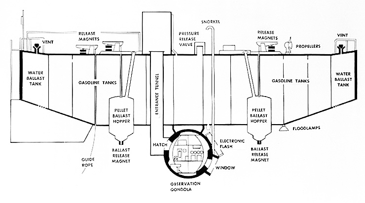
The Trieste is positively buoyant when loaded with ballast and floating on the surface before a mission. To submerge, Trieste would take on seawater and fill its fore and aft water ballast tanks. If needed to achieve the desired negative buoyancy, Trieste also could release some gasoline from the main float chamber. To achieve positive buoyancy at the end of a mission and ascend back to the surface, the pellets in the two ballast hoppers would be released, and Trieste would slowly rise to the surface.
The propulsion system consists of five special General Electric 3-hp dc motors. These motors are designed to operate in inert fluid (silicone oil) and are subjected to full ambient pressure during diving operations. These modest propulsors gave Trieste only limited mobility.
After acquisition by the Navy, Trieste was transported to San Diego, CA, for extensive modifications by the Naval Electronics Laboratory.
After a series of local dives in Southern California waters, Trieste departed San Diego on 5 October 1959 aboard a freighter and was transported to Guam to conduct deep dives in the Pacific Ocean under Project Nekton. After arriving in Guam, record-setting dives to 18,000 and 24,000 feet were conducted in nearby waters by Navy Lieutenant Don Walsh and Swiss engineer Jacques Piccard (son of Auguste Piccard). Then Trieste was towed to the Mariana Trench dive site, where Walsh and Piccard began their mission into the Challenger Deep on 23 January 1960.
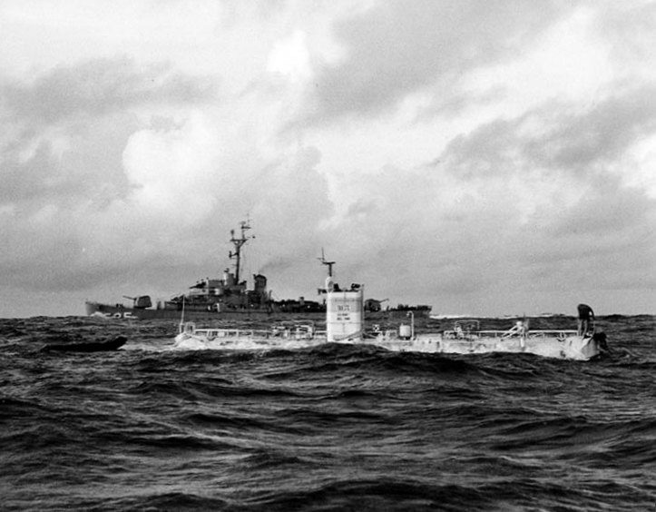
Source: U.S. Navy photo.
The mission took 8 hours and 22 minutes on the following timeline:
- Descent to the ocean floor took 4 hours 47 minutes. They reached the bottom at a depth of 10,916 meters (35,814 ft).
- Time on the bottom was 20 minutes.
- Ascent took 3 hours and 15 minutes.
For much of the mission, cabin temperature was about 7° C (45° F). While on the bottom, Walsh and Piccard observed sea life, although the species observed are uncertain. They described the sea bottom as a “diatomaceous ooze.”
For a comprehensive review of this historic dive into the Challenger Deep, I recommend that you watch the following video, “Rolex presents: The Trieste’s Deepest Dive,” (22:38).
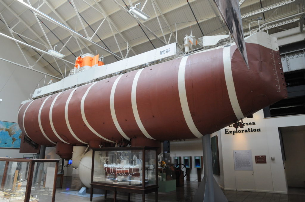
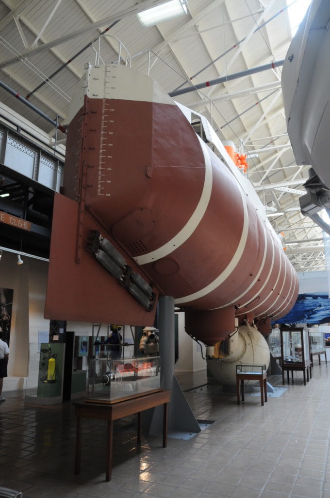
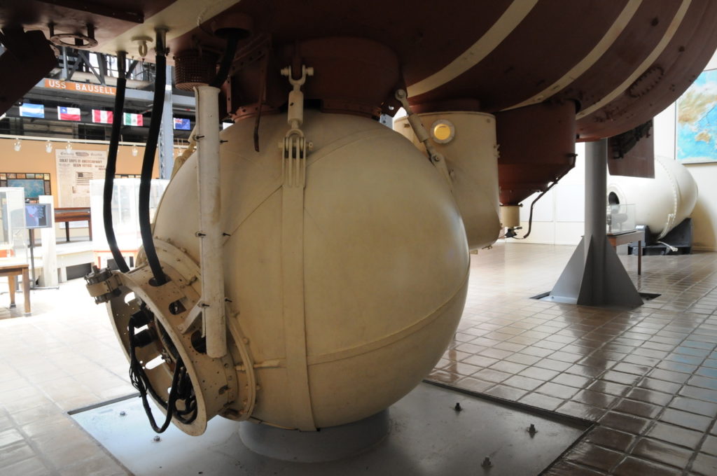
After successfully completing Project Nekton, Trieste underwent further modifications and was transferred to the East Coast in 1963 to assist in the search for the USS Thresher (SSN-593), which sank off the coast of New England. Trieste found the wreck of the nuclear submarine at a depth of 2,600 m (8,400 ft). Trieste was decommissioned in 1966 and went on display in 1980 at the National Museum of the U.S. Navy in Washington, D.C. Following are photos I took during my visit to that museum.
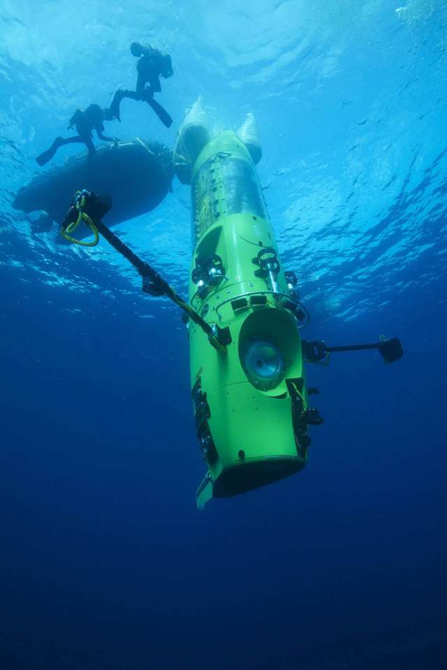
2012: James Cameron in the Deepsea Challenger
Almost a decade ago, filmmaker and National Geographic Explorer-in-Residence James Cameron led a team that designed and built the one-man, 11.8-ton DSV named Deepsea Challenger (DCV 1) for a mission to dive into the Challenger Deep and reach the deepest point in the ocean. The general arrangement of this novel submersible is shown in the following diagram.
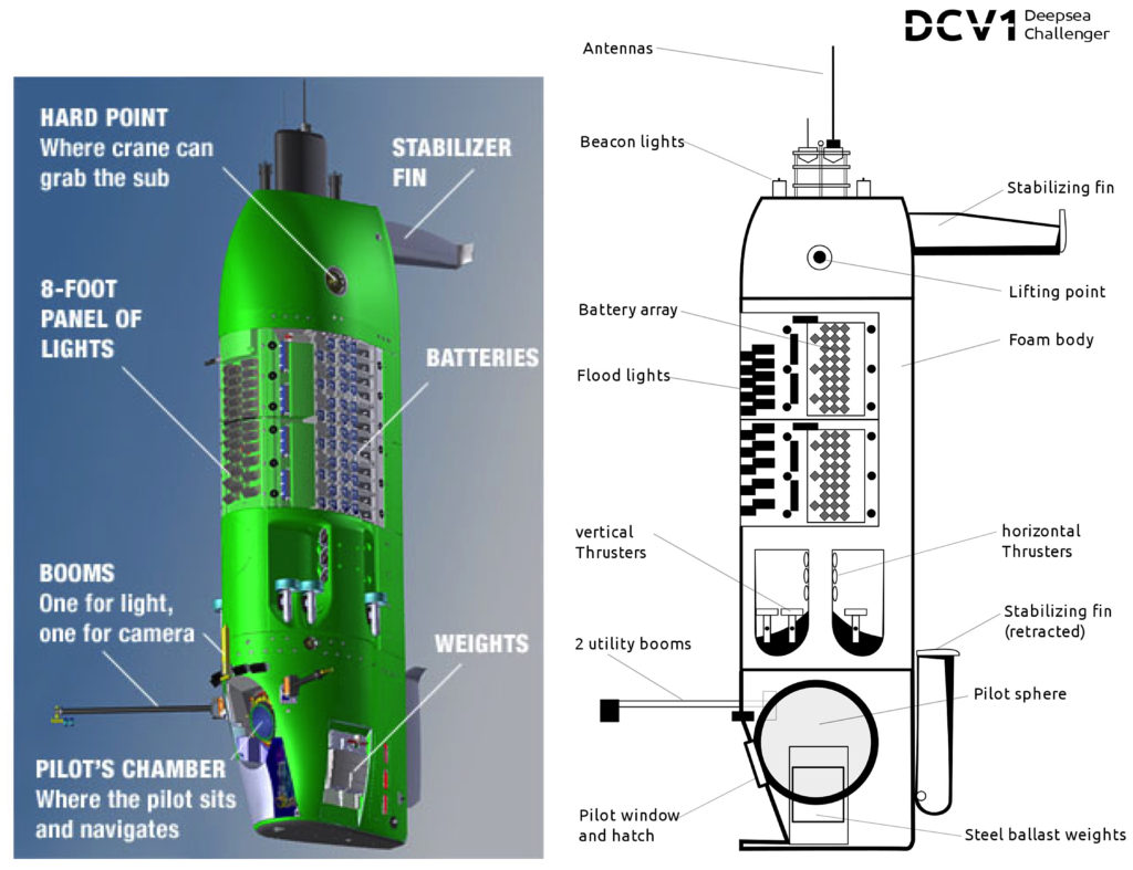
Sources: https://www.core77.com (left), Wikipedia (right)
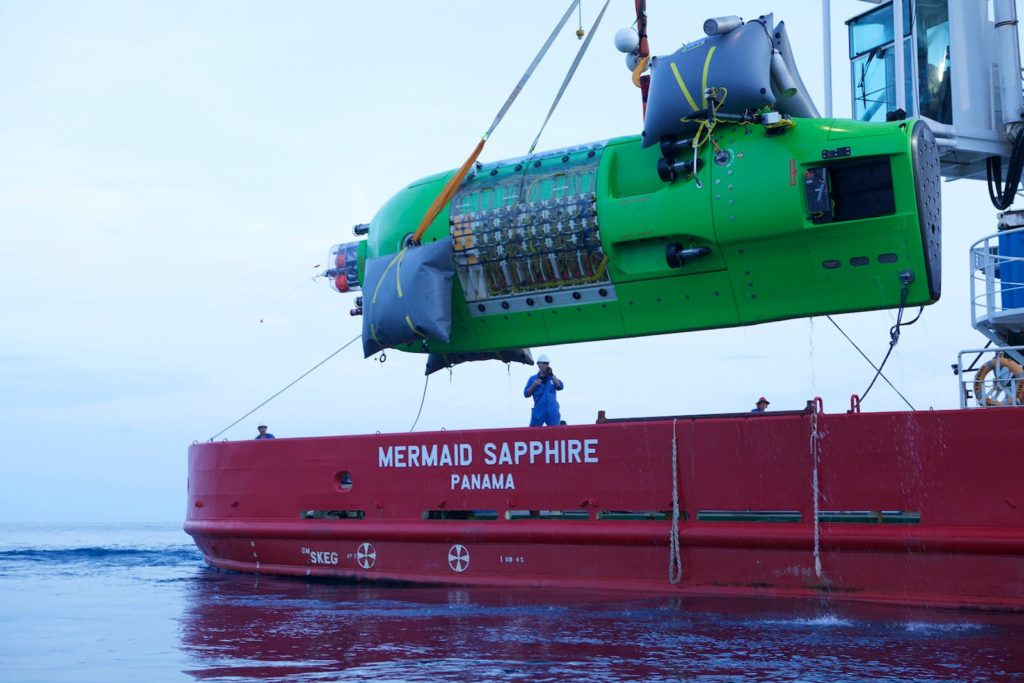
In the water, the submersible floats vertically with the steel pilot’s chamber at the bottom of the vessel. When brought aboard its support vessel, the submersible sits horizontally in a cradle.
About 70% of the Deepsea Challenger’s volume is comprised of a specialized structural syntactic foam called Isofloat, which is composed of very small hollow glass spheres suspended in an epoxy resin.
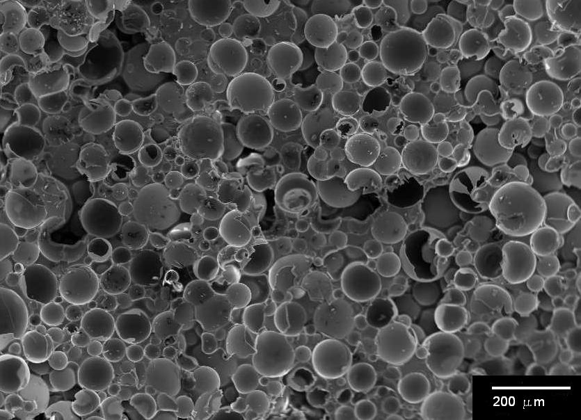
The strength of this structural foam enabled the designers to incorporate 12 thrusters as part of the infrastructure mounted within the foam, but without the need for a steel skeleton to handle the loads from the various mechanisms. The lithium batteries are housed within the syntactic foam structure. The foam also provides buoyancy, like the gasoline-filled float chamber on the bathyscaphe Trieste.
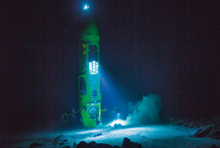
The Deepsea Challenger is equipped with a sediment sampler, a robotic claw, temperature, salinity, and pressure gauges, multiple 3-D cameras and an 8-foot (2.5-meter) tower of LED lights. An underwater acoustic communication system provides the communications link with the support vessel during the dive. Mission endurance is 56 hours.
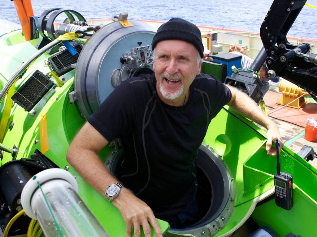
On March 26, 2012, more than 52 years after the Trieste’s dive into the Challenger Deep, Cameron plunged 10,908 meters (35,787 feet, 11 kilometers, 6.8 miles) below the ocean surface and became the first solo diver to reach such depths. After a two hour and 36 minute descent, he traveled along the bottom for about three hours and reported it being a flat plain with a soft, gelatinous sea floor. The thrusters enabled precise station keeping and a maximum speed of 3 knots.
Source: http://divemagazine.co.uk
after returning from the Challenger Deep. Source: National Geographic
Challenger Deep. Source: National Geographic
You can read a short summary of the mission here: https://www.nationalgeographic.com/news/2012/3/120326-james-cameron-mariana-trench-challenger-deepest-lunar-sub-science/#close
A National Geographic film of his expedition, Deepsea Challenge 3D, was released to cinemas in 2012. You can watch the short movie trailer (2:44) here:
Cameron was awarded the 2013 Nierenberg Prize for Science in the Public Interest for his deep dive into the Challenger Deep. In the following long video (58:25) “Journey to the Deep,” he shares his experiences and perspectives from his record-setting dive.
The Deepsea Challenger is retired from diving.
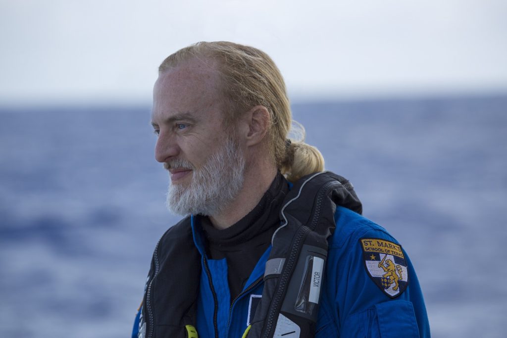
2019: Victor Vescovo and the Five Deeps Expedition
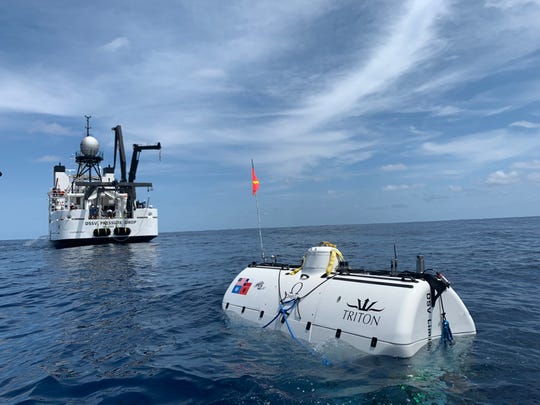
In 2015, businessman and explorer Victor Vescovo partnered with Triton Submarines LLC to design and build the two-person, 14-ton, titanium hull, deep-submergence vehicle Limiting Factor to enable Vescovo to conduct the Five Deeps Expedition to visit the deepest points in the world’s five oceans. The Five Deeps Expedition website is here:
https://fivedeeps.com/home/expedition/
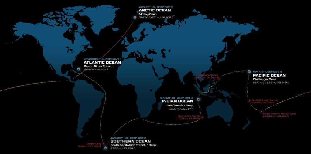
Between December 2018 and August 2019, the Five Deeps Expedition team accomplished this goal:
- Atlantic Ocean’s Puerto Rico Trench: December 2018; depth 8,375 meters (27,477 ft).
- Southern Ocean’s South Sandwich Trench: February 2019; depth 7,434 meters (24,388 ft).
- Pacific Ocean’s Mariana Trench / Challenger Deep: May 2019; depth 10,925 meters ± 6.5 meters (35,843 ft ± 21 ft).
- Indian Ocean’s Java Trench: April 2019; depth 7,192 meters (23,596 ft).
- Arctic Ocean’s Molloy Deep: 24 August 2019; depth 5,550 meters (18,209 ft).
During this period, the expedition covered 87,000 km (47,000 nautical miles) in 10 months and the Limiting Factor submersible completed 39 dives.
The DSV Limiting Factor is a Triton 36000/2 submersible that is designed for dives to 11,000 m / 36,000 ft and pressure tested to 14,000 m / 45,991 ft. Like James Cameron’s Deepsea Challenger, the Limiting Factor is constructed with glass-bead based syntactic foam, which is very durable and able to withstand the enormous pressure placed on the submersible as it descends thousands of meters into the sea, and does so repeatedly without significant deformation or stress fractures developing over time.
The Limiting Factor has a Kraft Telerobotics “Raptor” hydraulic manipulator capable of functioning at full-ocean depth. Mission endurance is 16 hours plus 96 hours of emergency life support.
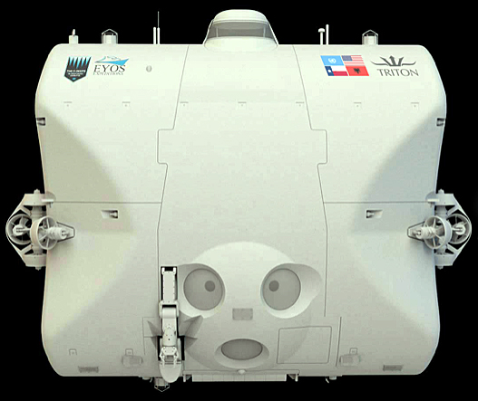
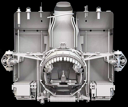
Source: Five Deeps Expedition
More details on the Triton 36000/2, also known as the Hadal Exploration System, are available here: https://fivedeeps.com/home/technology/sub/
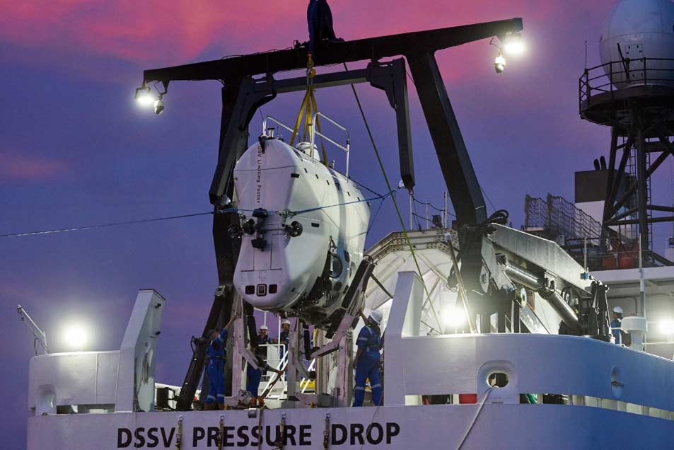
Using a Kongsberg EM124 multi-beam echo sounder mounted to the hull of the support vessel DSSV Pressure Drop, the Five Deeps Expedition team created detailed topographical maps of the Challenger Deep before the first of four dives. Dives 1 and 2 were conducted by Vescovo into the Eastern Pool. Dives 3 and 4 were conducted by Triton Submarines President, Patrick Lahey; Dive 3 was into the Eastern Pool and Dive 4 was into the Central Pool. Two days later, Dive 5 was conducted in the Sirena Deep. These five dives were accomplished in eight days. A synopsis of each dive follows:
- Dive 1 (28 April 2019): This was the deepest dive of the mission and the deepest dive in human history. Vescovo reached the bottom at a depth of 10,925 meters ± 6.5 m (35,843 ft ± 21 ft, 10.92 km, 6.79 miles). Time on the bottom was 248 minutes. Note that the maximum depth originally was reported as 10,928 meters ± 10.5 meters, but this was later corrected. See the depth certification here: https://fivedeeps.com/wp-content/uploads/2019/10/Triton-LF-Max-Depth-Confirmation-for-Dives-12-DNV-GL.pdf
- Dive 2 (3 May 2019): Vescovo reached a depth of 10,927 meters. Time on the bottom was 217 minutes.
- Dive 3 (3 May 2019): This was a commercial certification dive with Patrick Lahey piloting and Jonathan Struwe aboard as a specialist. A Five Deeps Expedition scientific lander that became stuck on bottom during Dive 2 was freed from the bottom and recovered from 10,927 meters by direct action of the manned submersible (deepest salvage operation ever). Time on the bottom was 163 minutes. The submarine passed all of its qualification tests and commercial certification by DNV GL was granted following this dive.
- Dive 4 (5 May 1959): This was a scientific dive with Patrick Lahey piloting and John Ramsay (the submarine’s designer) in the second seat. Video surveys were conducted and biological samples were collected. Time on the bottom was 184 minutes.
- Dive 5 (7 May 2019): While still in the Mariana Trench area, Lahey conducted the first ever dive into the Sirena Deep, 128 miles (206 km) northeast of the Challenger Deep. On this dive (Dive 5), he reached a depth of 10,714 meters (35,151 ft, 6.66 miles). Time on the bottom was 176 minutes.
Source: Triton Submarines LLC
Source: Five Deeps Expedition
You’ll find a good summary of the five dives in the Challenger Deep and Sirena Deep in the expedition’s press release dated 13 May 2019, “Deepest Submarine Dive in History, Five Deeps Expedition Conquers Challenger Deep,” which is available here:
https://fivedeeps.com/wp-content/uploads/2019/05/FDE-Challenger-Release-FINAL-5132019.pdf
The Five Deeps Expedition’s “Pacific Ocean Expedition Blog,” also provides an excellent overview of this mission at the following link:
https://fivedeeps.com/home/expedition/pacific/live/
The entire expedition was filmed by Atlantic Productions for a five-part Discovery Channel documentary series, “Deep Planet.”
Into the future
The Triton 36000/2 Limiting Factor is the only submersible that is commercially certified for repeated exploration to the deepest points in the ocean. It is the only insurable, full ocean depth (FOD) manned submersible in the world. The official certification of the vessel to FOD is overseen by an independent third party, the world-standard credentialer of maritime vessels DNV-GL (Det Norske Veritas Germanischer Lloyd).
The manufacturer, Triton Submarines LLC, located in Vero Beach, Florida reported:
- “Designed and certified to make thousands of dives to Hadal depths, during decades of service, Triton is excited to offer the opportunity for a private individual, government or philanthropic organization or research institute to acquire this remarkable System and continue the adventure.”
- “Available to purchase today for $48.7 million, the Triton 36,000/2 Hadal Exploration System will be ready for delivery in 2019, after its successful (Five Deeps) expedition. The System will be fully proven. It will have extended the boundaries of human endeavor and technology. And it will offer a unique deep-diving capability unmatched by any nation or organization in the world.”
The Triton website is here: https://tritonsubs.com
They’re waiting to take your order.